There are two types of electrical wiring for the VAZ-2110: carburetor and injector. There are slight differences, but the basic principles of operation and wiring are the same. Depending on the location, the wiring differs into: under the hood and in the cabin. All electrical equipment of the car is connected using wires of a certain color. Each element has its own wiring harness through the blocks and fuses.
VAZ 2110 - modifications
VAZ-21100 . The base model which was produced from 1996 to 2000. The car was equipped with an 8-valve carburetor VAZ-21083 engine with a displacement of 1.5 liters and a power of 69 horsepower.
VAZ-21101 . This modification has been produced since 2004, equipped with an 8-valve gasoline injection engine with a displacement of 1.6 liters.
VAZ-21102. Like the previous modification with an 8-valve injection engine, but with a volume of 1.5 liters.
VAZ-21103 . Modification of the “tens” with a 16-valve injection engine with a working volume of 1.5 liters.
VAZ-21103M . A restyled modification of the VAZ-21103, equipped with a 16-valve petrol injection engine with a displacement of 1.5 liters and a power of 92 horsepower. Produced since 2002.
VAZ-21104 . The modification is equipped with a 16-valve petrol injection engine with a working volume of 1.6 liters.
VAZ-21104M . A restyled modification of the VAZ-21104, equipped with a 16-valve petrol injection engine with a displacement of 1.6 liters. Produced since 2004.
VAZ-21106 GTI . The engine of the VAZ-21106 GTI is the most powerful and expensive modification that has been produced since 2000. The car was equipped with a 2-liter 16-valve Opel C20XE gasoline engine with a capacity of 150 horsepower. The car was fitted with a body kit with swollen arches, and the track was widened by 76 millimeters. It was equipped with R15 wheels with low-profile tires.
VAZ-21106 Coupe . Coupe VAZ-21106 in a coupe body. A distinctive feature of the car was the presence of only two doors, which were lengthened by 250 millimeters, while the body was shortened by 170 millimeters. The engine was installed the same as in the previous VAZ-21106 GTI model.
VAZ 21106 WTCC . A sports modification of the 106 model, it participated in the 2008 FIA WTCC international championship.
VAZ 21107 . Modification of a car for rally competitions. It was equipped with a welded safety cage and a different suspension design.
VAZ 21108 "Premier" . A modification with a body lengthened by 170 millimeters in the rear door area, which provided more convenient entry and exit of passengers. It was equipped with a 1.5-liter injection 16-valve engine.
VAZ 21109 “Consul” . 4-seater luxury limousine based on the VAZ-2110 car. In addition to the length of the body, the dimensions of the rear door were also increased, for more convenient entry and exit of passengers. Equipped with a 1.5 liter engine and R14 or R15 wheels. Overall dimensions: length – 4950 mm, width – 1700 mm, height – 1440 mm. Fuel consumption in the urban cycle is 9.5 liters per 100 kilometers.
VAZ 2110-91 . Modification of the VAZ-2110 with a 1308 cm3 rotary piston engine. The car could reach speeds of up to 240 km/h, and acceleration from 0 to 100 km/h took 6 seconds.
A car with a 16-valve injection engine in the “Gran Lux” configuration includes:
- Electric windows;
- Door locking;
- Trunk lock lock;
- Velvet seat upholstery;
- Immobilizer;
- Heated front seats;
- Ventilated 14-inch brake discs;
- Rear spoiler with additional brake light;
- Fog lights.
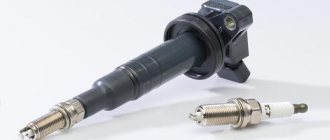
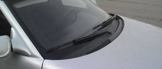
Do-it-yourself modification and replacement of wipers
Which wipers are better is up to the car owner to decide. Those installed on the VAZ 2110, as well as on the UAZ, do their job well from the factory, but it can be modified with washers from other companies that are of higher quality. Many people are attracted to frameless brushes - this is a good option. They are compact in size and equipped with a special leash mechanism. True, they do not look very attractive on the VAZ 2110, since the fastener to the standard washer arm turns out to be massive. Therefore they need improvement.
Frameless car washers
To perform a replacement or modification, you must perform the following steps:
- First you need to disconnect the negative terminal on the battery.
- Then you need to tilt the mount towards you and remove the brush.
- If there is a decorative trim, it must be removed.
- By unscrewing the bolt, you can remove the old brush.
- Before replacing parts, be sure to check the dimensions of the new washer with the old one. It is advisable that the new one does not exceed the size of the old one by more than 2 cm.
- Installation of the new kit is carried out in the reverse order.
After upgrading, you should check the functionality of the unit: whether the brushes creak, how they work when switching modes. At high speeds of the windshield wiper motor, the wipers should work quickly, at low speeds - slowly. In addition, they must support intermittent operation.
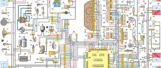
Wiring diagram for VAZ 2110 carburetor
In the instrument panel wiring harness, the second ends of the wires of white, black, orange, white with a red stripe and yellow with a blue stripe are connected to each other at the same points. The bends of the wires at the points of entry into the harness indicate the direction of their laying in the bundle.
See the complete diagram in one file below (click to enlarge):
1 – headlight 37 – instrument cluster 2 – front brake pad wear sensor 38 – rear fog light switch 3 – fan motor switch 39 – fog light indicator lamp 4 – engine cooling system fan electric motor 40 – rear window heating indicator lamp 5 – sound signal 41 – clock 6 – generator 42 – rear window heating switch 7 – oil level sensor 43 – steering column switch 8 – carburetor solenoid valve control unit 44 – block for switching wires when installing headlights of another type 9 – heater controller 45 – switch instrument lighting 10 – recirculation valve switch 46 – ignition switch 11 – illumination lamp for heater control levers 47 – connectors for connecting the headlight cleaner wiring harness 12 – switch 48 – socket for a portable lamp 13 – carburetor limit switch 49 – directional light 14 – control sensor oil pressure lamps 50 – brake light switch 15 – spark plugs 51 – interior lamp 16 – carburetor solenoid valve 52 – on-board control system unit 17 – coolant temperature indicator sensor 53 – fuel level indicator sensor 18 – ignition distributor 54 – hazard warning switch 19 – ignition coil 55 – driver’s seat belt sensor 20 – starter 56 – cigarette lighter 21 – heater fan motor 57 – ashtray backlight lamp 22 – additional resistor for heater motor 58 – glove compartment light switch 23 – speed sensor 59 – connector for on-board computer 24 – reverse light switch 60 – glove box lighting lamp 25 – micromotor gearbox for heater flap drive 61 – side turn signal 26 – recirculation valve 62 – switch in the front door pillar 27 – brake fluid level sensor 63 – switch in the rear door pillar 28 – pads for connecting the rear window washer motor 64 – parking brake warning lamp switch 29 – battery 65 – trunk light 30 – windshield washer motor 66 – interior air temperature sensor 31 – washer fluid level sensor 67 – external rear light 32 – level sensor coolant 68 – internal rear light 33 – windshield wiper motor 69 – license plate light 34 – mounting block 70 – block for connecting the rear window heating element 35 – blocks for connecting the warning light harness 71 – block for connecting an additional brake signal 36 – outdoor light switch
Diagram of VAZ 2110 injector 8 valves
1 – headlight 2 – front brake pad wear sensors 3 – horn 4 – cooling system fan 5 – reverse light switch 6 – battery 7 – generator 8 – oil pressure warning lamp sensor 9 – oil level sensor 10 – spark plugs 11 – injectors 12 – idle speed control 13 – electronic control unit blocks 14 – throttle position sensor 15 – crankshaft position sensor 16 – ignition module 17 – coolant temperature indicator sensor (for instrument cluster) 18 – starter 19 – diagnostic block 20 – coolant temperature sensor (for the engine management system) 21 – speed sensor 22 – fuel pump switch relay 23, 35, 39 – fuses 24 – electric fuel pump 25 – micromotor gearbox for heater damper drive 26 – recirculation valve 27 – heater fan 28 – windshield washer pump windows 29 – washer fluid level sensor 30 – brake fluid level sensor 31 – coolant level sensor 32 – windshield wiper gear motor
33 – additional heater fan resistor 34 – injection system power supply relay 36 – canister purge valve 37 – mass air flow sensor 38 – cooling system fan activation relay 40 – external lighting switch 41 – knock sensor VAZ-2110 injector 42 – oxygen concentration sensor ( heated lambda probe) 42* – CO potentiometer (installed on cars running on leaded gasoline; in this case, an oxygen concentration sensor is not installed) 43 – fog light indicator lamp 44 – rear window heating indicator lamp 45 – fog light switch 46 – rear window heating switch 47 – instrument cluster 48 – mounting block 49 – fuel level sensor 50 – ignition switch 51 – instrument backlight brightness control 52 – steering column switch 53 – heater control lever illumination lamp 54 – hazard warning switch 55 – electronic heater control unit; 56 – recirculation valve switch 57 – on-board control system display unit 58 – side direction indicators 59 – temperature sensor for the heating system 60 – interior lamp 61 – front interior lamp 62 – socket for a portable lamp 63 – electronic clock 64 – switches in the racks front doors 65 – switches in the rear door pillars 66 – glove compartment lighting lamp 67 – glove compartment lighting switch 68 – cigarette lighter 69 – ashtray lighting lamp 70 – brake light switch 71 – rear window heating element 72 – external rear lights 73 – internal rear lights 74 – license plate lamps 75 – trunk lighting lamp
See the complete diagram in one file below (click to enlarge):
Diagram of VAZ 2110 injector 16 valves
1 – headlight unit 35 – instrument lighting switch 2 – front brake pad wear sensors 36 – ignition switch 3 – reverse light switch 37 – mounting block 4 – engine cooling system fan electric motor 38 – recirculation valve switch 5 – sound signal 39 – controller heater 6 – right front door locking motor 40 – hazard warning switch 7 – power window relay 41 – heater control lever illumination lamp 8 – 8 A fuse 42 – glove compartment lighting lamp 9 – starter 43 – glove compartment lighting lamp switch 10 – battery 44 – cigarette lighter 11 – generator 45 – on-board control system display unit 12 – windshield washer motor 46 – ashtray lighting lamp 13 – washer fluid level sensor 47 – brake signal switch 14 – left front door locking motor 48 – locking motor left rear door 15 – power window switch of the left front door 49 – power window switch of the left rear door 16 – coolant level sensor 50 – power window motor of the left rear door 17 – windshield wiper motor 51 – socket for a portable lamp 18 – recirculation valve 52 – clock 19 – micromotor gearbox for heater flap drive 53 – gearmotor for electric window lift of the right rear door 20 – electric motor for heater 54 – power window switch for the right rear door 21 – trunk lock switch 55 – gearmotor for locking the right rear door 22 – power window switch for the right front door 56 – side turn signal 23 – electric window motor of the right front door 57 – parking brake warning lamp switch 24 – door lock system control unit 58 – driver’s seat belt sensor 25 – additional resistor for the heater motor 59 – directional lamp 26 – brake fluid level sensor 60 – interior lamp 27 – electric window motor of the left front door 61 – interior air temperature sensor 28 – exterior lighting switch 62 – switch in the front door pillar 29 – instrument cluster 63 – switch in the rear door pillar 30 – rear fog light switch 64 – external rear lamp 31 – control lamp fog light 65 – interior rear light 32 – rear window heating indicator lamp 66 – license plate lights 33 – rear window heating switch 67 – trunk light 34 – steering column switch A – blocks for connecting the rear window washer motor B – blocks for connecting the harness injection system C – to the warning light harness connector D – connector for connecting to the on-board computer E – to the headlight cleaner harness connector F – connector for connecting to the fuel level sensor in the electric fuel pump module G – to the rear window heating element H – connector for connecting an additional signal braking J – to the trunk lock motor
Useful: VAZ-2121 Niva diagram
See the complete diagram in one file below (click to enlarge):
The following (9) users say Thank You to pioneerxp2 for this post:
The power circuit of these lamps includes a relay-breaker K3, which alternately closes contacts 49a and 49a Register on site 2. It all started with the fact that I began to be wildly annoyed by the breakdowns of the two-piece, it seemed like nothing serious had broken, but there were so many little things, damn it, which was really starting to piss me off. Locking the trunk lock. Indicator lamp for turning on the high beam.
The only nuance of switching from a carurator to an injector is the need to install additional wiring from the fuel pump to the on-board computer.
F14 - 10A - Left fog lamp. They turn on regardless of the relay activation. To prevent this situation, it is better to connect the relay control wire to the terminal from the ignition switch in red in the diagram. It is regulated only by the limit switch
Article Archives
Depending on the location, the wiring differs into: under the hood and in the cabin. Injector In addition to the wiring, which is identical for the carburetor and injector, the latter is additionally equipped with fuses and sensors.
This is done to reduce the load on the battery when the engine is not running and prevent its discharge. It is regulated only by the limit switch. Side light indicator lamp.
But this does not take away the fact that many have dozens of them under the hood with a carburetor. F3 - 10A - Left headlight high beam. These positions correspond to the inclusion of indicator 5 on the device. F2 - 7.5A - Left headlight low beam. Connecting the VAZ ECU harness
Electrical circuit of ECM VAZ-21101
1 – VAZ-21101 controller; 2 – block of the ignition system harness to the ABS cabin group harness; 3 – diagnostic block; 4 – immobilizer warning sensor; 5 – immobilizer control unit; 6 – ignition coil; 7 – spark plugs; 8 – nozzles; 9 – electric fuel pump; 10 – block of the ignition system harness to the fuel level sensor harness; 11 – block of the fuel level sensor harness to the ignition system harness; 12 – block of the ignition system harness to the injector harness; 13 – injector harness block to the ignition system harness; 14 – speed sensor; 15 – idle speed regulator; 16 – throttle position sensor; 17 – coolant temperature sensor; 18 – mass air flow sensor; 19 – oil pressure warning lamp sensor; 20 – phase sensor; 21 – oxygen sensor; 22 – crankshaft position sensor; 23 – knock sensor; 24 – solenoid valve for purge of the adsorber; 26 – coolant temperature indicator sensor; 27 – ignition system harness block to the instrument panel harness; 28 – instrument panel harness connector to the ignition system harness; 29 – controller power supply fuse; 30 – ignition relay; 31 – ignition relay fuse; 32 – fuse for the power supply circuit of the electric fuel pump; 33 – electric fuel pump relay; 34 – electric fan relay; 35 – ignition system harness block to the air conditioner connector; 36 – block of the ignition system harness to the side door harness. 37 – electric fan of the cooling system; 38 – diagnostic connector; 39 – ignition switch; 40 – instrument cluster; 41 – on-board control system unit; 42 – starter relay; 43 – contacts of the 8-terminal blocks of the instrument panel harness and the front harness; 44 – contacts of the 21-terminal blocks of the instrument panel harness and the rear harness; 45 – trip computer.
- A – to the “plus” terminal of the battery;
- B1 – grounding point of the fuel level sensor harness;
- B2, B3 – grounding points of the ignition system harness;
- C – to the starter;
- D – to the driver’s door interior lamp switch.
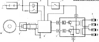
Engine control circuit VAZ-21102, 21103
Engine control circuit for VAZ-21102, VAZ-21103 (controller M1.5.4N, “January-5.1”).
1 - injectors 2 - spark plugs 3 - ignition module 4 - diagnostic block 5 - controller 6 - block connected to the instrument panel wiring harness 7 - main relay 8 - fuse connected to the main relay 9 - electric fan relay 10 - fuse connected to electric fan relay 11 – electric fuel pump relay 12 – fuse connected to the electric fuel pump relay 13 – mass air flow sensor 14 – throttle position sensor 15 – coolant temperature sensor 16 – idle speed regulator 17 – VAZ-21102 oxygen sensor 18 – knock sensor 19 – Crankshaft position sensor 20 – canister purge solenoid valve 21 – immobilizer control unit 22 – immobilizer status indicator 23 – vehicle speed sensor 24 – electric fuel pump with fuel level sensor 25 – oil pressure warning lamp sensor 26 – coolant temperature indicator sensor 27 – level sensor oil 28 - phase sensor (installed on a car with a 16-valve engine) A - block connected to the wiring harness of the anti-lock brake system (ABS) B - block connected to the air conditioner wiring harness C - block connected to the electric fan wiring harness D - wires , connected to the ignition switch (backlight lamp) E - block connected to the blue-white wires disconnected from the ignition switch (when installing the immobilizer) F - to the “+” terminal of the battery G1, G2 - grounding points The diagram uses the designation of the element number circuit to which this wire is connected, for example “-4-”. In some cases, in addition to the designation of the element number, it is given through an oblique fraction and the contact number, for example “-5/15-”. The diagram does not show the connection points of the pink-black, red and green with a red stripe wires.
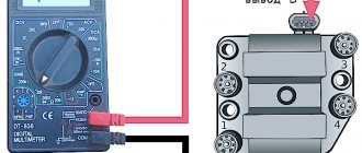
Pinout of 8-pin connector
- power supply
- speed sensor (electric speedometer)
- fuel consumption (for BC)
- coolant sensor
- emergency oil pressure
- check lamp
- oil level sensor
- tachometer signal
Removing the car dashboard
- Using a Phillips screwdriver, remove the three screws that secure the center console;
- remove the cover, the protrusion located at the bottom, remove the protrusion from the bracket;
- Using a nozzle, unscrew the five screws located in the console on the right and remove the screen;
- Disconnect the terminal with the (-) sign from the battery. If there is a radio receiver, you need to remove it, remove the plug from the shield;
- Disconnect the wires coming from the cigarette lighter, remove the cartridge;
- Using a narrow screwdriver, remove the handle from the levers;
- pull the handle towards the heating and fan switch;
- unscrew the two screws above the panel and the two located under it using a screwdriver;
- unscrew the screw located behind the panel;
- Also unscrew the two self-tapping screws securing the cover;
- disconnect the harness and wire connectors. To avoid confusion when installing the panels, you should mark the order in which they are connected;
- unscrew the fastening bolts;
- unscrew the two self-tapping screws, those that secure the bottom bracket using an 8 key;
- unscrew the self-tapping screw securing the light guide and remove it;
- Also unscrew the screws securing the heating unit;
- remove lamp sockets;
- after removing the external parts, remove the decorative insert;
- unscrew all nuts with a 21 key;
- hydrocorrector, remove its lamp;
- Unscrew the screws that are attached to the cross member on the left.
- Finally, the panel itself is removed. The panel is assembled accordingly in the reverse order.
In general, the repair work is quite doable even with your own hands, but before starting dismantling work, you need at least a pinout mapped on paper, otherwise it will be difficult: you will need to “trace” every wire and every connection that is on the “path” from devices to the power button.
Electrical circuit of ECM VAZ-21104
1 – block of the ignition coil wiring harness to the ignition system harness; 2 – block of the ignition system harness to the ignition coil wiring harness; 3 – ignition coils VAZ-21104; 4 – immobilizer warning sensor; 5 – immobilizer control unit; 6 – spark plugs; 7 – nozzles; 8 – diagnostic block; 9 – block of the ignition system harness to the ABS cabin group harness; 10 – controller; 11 – electric fuel pump; 12 – block of the ignition system harness to the fuel level sensor harness; 13 – fuel level sensor harness connector to the ignition system harness; 14 – block of the ignition system harness to the injector harness; 15 – injector harness block to the ignition system harness; 16 – block of the ignition system harness to the side door harness; 17 – speed sensor; 18 – idle speed regulator; 19 – throttle position sensor; 20 – coolant temperature sensor; 21 – mass air flow sensor; 22 – oil pressure warning lamp sensor; 23 – phase sensor; 24 – oxygen sensor; 25 – crankshaft position sensor; 26 – knock sensor; 27 – solenoid valve for purge of the adsorber; 28 – oil level sensor; 29 – coolant temperature indicator sensor; 30 – block of the ignition system harness to the instrument panel harness; 31 – instrument panel harness connector to the ignition system harness; 32 – ignition relay; 33 – ignition relay fuse; 34 – fuse for the electric fuel pump power supply circuit; 35 – electric fuel pump relay; 36 – electric fan relay; 37 – controller power supply fuse; 38 – ignition system harness block to the air conditioner connector; 39 – instrument cluster; 40 – ignition switch; 41 – electric fan of the cooling system; 42 – on-board control system unit; 43 – starter relay; 44 – contacts of the 8-terminal blocks of the instrument panel harness and the front harness; 45 – contacts of the 21-terminal blocks of the instrument panel harness and the rear harness; 46 – trip computer; 47 – diagnostic connector.
- A – to the “plus” terminal of the battery;
- B1 – grounding point of the ignition coil wiring harness;
- B2 – grounding point of the fuel level sensor harness;
- B3, B4 – grounding points of the ignition system harness;
- C – to the starter;
- D – to the driver’s door interior lamp switch.
According to the scheme described above, fuel regulation in a car is carried out. Moreover, it depends not only on the load of the valves in the engine, but also on the corresponding position relative to the throttle valve. With the help of a diagram of electrical wiring and valves, it is possible to understand which of the relays or fuses is malfunctioning and replace it in time. In this case, one of the main roles when supplying fuel is played by electrical equipment (controllers) that regulates the operation of the injector.
Repair
To repair this unit, you need a minimum of tools:
- Set of keys and sockets.
- Screwdriver Set.
- WD-40.
- Rags.
- Replacement parts.
It is quite easy to determine which parts are not working. For example, if the wipers do not move, then the motor has failed. If the trapezoid moves, but the glass remains dirty, then the pump or tank is damaged. The size will help you understand what condition the part is in - if the size has decreased too much, then the element needs to be changed. In any case, you need to make sure of the speculations; for this you should analyze:
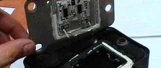
- The first step is to dismantle the car's dashboard;
- Next you need to find the relay related to this mechanism. It is screwed to the body of the VAZ 2110. If the electrical elements do not work, then the relay needs to be changed; repairs will not help;