The VAZ-2112 car was produced at AvtoVAZ from 1998 to 2009, in Ukraine from 2009 to 2014. The following are color wiring diagrams (injector and carburetor) with a description of all elements for various modifications. The information is intended for self-repair of cars. Electrical circuits are divided into several blocks for ease of viewing via a computer or smartphone; there are also circuits in the form of a single picture with a description of the elements - for printing on a printer in one sheet.
To diagnose and repair yourself, first look to see if everything is okay with the generator. Is it put on well and does not sag? This procedure must be done with all versions of the fuel system, both carburetor and injection.
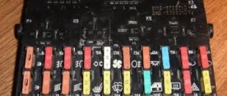
We check the fuses according to the electrical diagram. The reverse side of the safety block cover will also be of great help. There are clues there that the diagram will help you decipher.
Replace the burnt out element and try to start the car again. You need to check whether the battery terminals are tightly connected and whether they are oxidized. Is the wire going from the battery to the generator and to the starter damaged?
Modifications of the VAZ-2112 car
VAZ-21120 . Modification with a 16-valve injection engine with a volume of 1.5 liters and a power of 93 horsepower. 14-inch wheels were installed on the car. This modification has a problem with valves bending when the timing belt breaks. The problem can be solved by increasing the depth of the grooves in the piston bottoms.
VAZ-21121 . The car was equipped with a VAZ-21114 8-valve injection engine with a volume of 1.6 liters and a power of 81 horsepower.
VAZ-21122 . Budget modification with an 8-valve injection engine VAZ-2111. The car was produced without electric windows, the wheels were 13 inches in size, and the brakes were unventilated from a VAZ-2108 car.
VAZ-21123 Coupe . Three-door, five-seater hatchback. The only two doors for entering the car are 200 millimeters wider than those of the five-door hatchback, and they are mounted on new, durable hinges. The rear arches of the car have become wider. The engine was installed with a 16-valve injection engine with a volume of 1.6 liters and a power of 90 horsepower. The car was produced from 2002 to 2006 in small quantities, the reason for this was the high cost of the car.
VAZ-21124 . Modification with a 16-valve injection engine VAZ-21124 with a volume of 1.6 liters. Produced from 2004 to 2008. For this type of engine, the problem with valve bending was solved. To do this, the depth of the grooves in the piston heads was increased (up to 6.5 mm). In addition, the design of the cylinder block was changed to achieve a working volume of 1.6 liters, for which its height was increased by 2.3 mm, and the radius of the crankshaft was increased by 2.3 mm accordingly. There were also a number of other minor changes.
VAZ-21128 . The luxury version of the car, produced by Super-auto JSC, was equipped with a 16-valve VAZ-21128 engine with a volume of 1.8 liters and a power of 105 horsepower.
VAZ-2112-37 . A racing modification of the VAZ-2112, prepared for the “ring” in the Lada Cup qualifying group. The car was equipped with a 1.5-liter VAZ-2112 engine with a power of 100 horsepower. The racing car was equipped with a safety cage, an external aerodynamic kit and a front extension of the strut support cups.
VAZ-2112-90 Tarzan . All-wheel drive modification with a VAZ-2112 body on a frame chassis with transmission and suspension parts from a VAZ-21213 Niva. It was also equipped with a 1.7 or 1.8 liter engine from the Niva.
Injection system design
F2 - 7.5A - Left headlight low beam.
Subsequently, the controller, based on the information coming from the on-board computer, makes a decision on the position and duration of opening of the injector damper. In principle, a novice motorist can understand its operation. In this case, the problem definitely does not lie in the control unit, the problem is related to malfunctions in the controller. The role of the electronic control unit in the overall injector circuit. From a practical point of view, the electronic control unit consists of several high-tech components: ROM - memory devices, PROM - dynamic memory devices, RAM - regulatory memory; all of the above elements function only if there is voltage available . Relay for monitoring the health of brake light lamps and side lights. There are slight differences, but the basic principles of operation and wiring are the same. But this does not take away the fact that many have dozens of them under the hood with a carburetor. The crankshaft, rotating, fills the cylinder with fuel, the size of its volume is determined by the state of the injector, and the operation of the injector is carried out by the controller. Thanks to this program, the moment and volume of gasoline supply to the chambers where internal combustion occurs is set.
The positive terminal that comes from the battery to consumers is always red. Unstable operation at low speeds. Generator excitation winding. For each system that is connected to the electrical system, it is equipped with its own separate wiring harness. Advice: make sure that the pressure in the fuel supply system does not exceed MPa.
Indicator lamp for turning on the high beam. How to look for faults? A pump is built in to supply gasoline and maintain the required pressure in the rail. The collapsible design allows for vehicle maintenance and repair. Checking the wires using a multimeter with the battery disconnected.
To check their condition, you need to carefully inspect all the wires that are laid in the harness. However, without protection on the VAZ there is: A wire from the battery charge relay to the battery itself, VAZ wiring to the injector, which is responsible for the ignition and engine starting circuits; Generator wiring excluding the field winding, which is activated after turning the key in the ignition and starting the engine. It allows you to move the damper, changing the angle of its opening, as well as the amount of cold air entering the heater from outside. VAZ 2110 21124 engine troubles, stalls, twitches (problem solution)
Electrical diagram of VAZ-2112
Designations: 1 – Headlight, 2 – Klaxon, 3 – Main radiator fan, 4 – Starter, 5 – Battery, 6 – Generator 2112, 7 – Gearbox limit switch (reverse), 8 – Actuator in the front passenger door, 9 – Power window enable relay, 10 – Starter relay, 11 – Heater fan, 12 – Electric heater partition drive, 13 – Main pump, 14 – Washer reservoir sensor, 15 – Driver’s door actuator, 16 – Front passenger window selector, 17 – Unlock button fifth door, 18 – Heater fan resistance unit, 19 – Main wiper motor, 20 – Driver’s window lift selector, 21 – Front passenger’s window lift motor, 22 – Central locking, 23 – Exterior light switch, 24 – Brake fluid leakage sensor, 25 – Pump additional, 26 – Driver's window lift motor, 27 – PTF on indicator, 28 – PTF switch, 29 – Dashboard, 30 – Heated glass on indicator, 31 – Heated glass switch, 32 – Steering column selector switch, 33 – PTF relay, 34 – Ignition switch, 35 – Main fuse block, 36 – Illumination of heater controls, 37 – Hazard warning button, 38 – Heater control controller, 39 – Glove compartment lighting, 40 – Glove compartment lid end cap, 41 – Cigarette lighter, 42 – BSK – display unit, 43 – Ashtray illumination, 44 – 12V socket, 45 – Instrument lighting switch, 46 – Actuator in the right rear door, 47 – Right rear passenger window selector, 48 – Clock, 49 – Right rear passenger window motor, 50 – Brake limit switch (closed – pedal is pressed), 51 – Left rear passenger window motor, 52 – Left rear passenger window selector, 53 – Actuator in the left rear door, 54 – Turn signal, 55 – Handbrake limit switch (closed – handbrake on), 56 – Rear wiper motor , 57 – Navigator's lamp, 58 – Interior lamp, 59 – Temperature sensor in the heater, 60 – Limit switch for the open front door, 61 – Limit switch for the open rear door, 62 – Trunk light, 63 – Rear optics (on the body), 64 – Rear optics (on the fifth door), 65 – License plate illumination.
The letters indicate the terminals to which it is connected: A – Front speaker on the right, B – Radio, C – Injector harness, D – ESD diagnostic connector, D – Front left speaker, E – Diagnostic connector for the heater controller, G – Rear right speaker, W – Rear left speaker, I – BC connector, K – glass heater thread, L – fifth door actuator, M – Additional brake light.
Wiring diagram VAZ-2112 injector 16 valves - full view
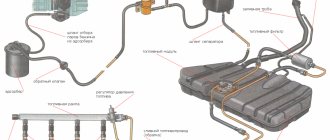
Detailed diagram of the fuel system
Detailed diagram of the fuel system.
1 — nozzles; 2 — fitting plug for monitoring fuel pressure; 3 — injector ramp; 4 — bracket for fastening fuel pipes; 5 — fuel pressure regulator; 6 — adsorber with solenoid valve; 7 — hose for suction of gasoline vapors from the adsorber; 8 — throttle assembly; 9 - two-way valve; 10 - gravity valve; 11 - safety valve; 12 - separator; 13 — separator hose; 14 — fuel tank plug; 15 - filling pipe; 16 — filling pipe hose; 17 — fuel filter; 18 — fuel tank; 19 — electric fuel pump; 20 — fuel drain line; 21 - fuel supply line.
Below we will look at the main elements of the fuel system separately.
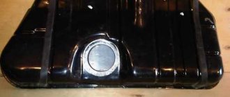
Fuel tank
Dismantled VAZ-2112 gas tank.
The filled gasoline is supplied from the tank, which is located in the rear of the car, in the area where the sofa is located . The tank is made of steel and assembled by welding two stamped parts. Gasoline is supplied to the tank through a special neck, from a gas-resistant hose made of rubber, secured together with clamps.
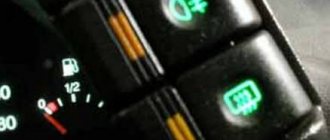
Gasoline pump
Fuel pump VAZ-2112 1139009
A gas pump is an electrical functional device, submersible, installed directly into the gas tank itself. This pump is started by a signal from the ECU controller, which is responsible for fuel injection, through a relay when the ignition is turned on. If the fuel pump doesn't pump, the engine won't start! The operating pressure of the pump is at least 2.8-3 bar (atmospheres - approx.). In order to get to it, just lift the rear sofa and unscrew the technical hatch.
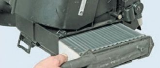
Fine filter
The new filter is ready for installation.
From the fuel pump, through a flexible steel hose, gasoline passes under pressure to the fine filter. The filter is made of steel and cannot be disassembled. A special paper filter element is installed inside. On the housing cover there is a special arrow, created for visual indication during installation, showing the direction of movement of gasoline in the system.
Fuel rail
Through steel fuel pipes, after filtration, gasoline passes directly to the fuel rail. It is designed to transfer gasoline to atomization and is mounted on the “outlet”. On one side of the fuel rail there is an RTD, on the other there is a fitting for controlling gasoline pressure. The pressure in the ramp in operating condition should be from 2.8 to 3.2 bar ( 2.8-3.2 atmospheres - approx.) - this indicator depends on the stabilization in the receiver, indicating constant differences in them. This is necessary in order to dose the optimal amount of gasoline into the injectors.
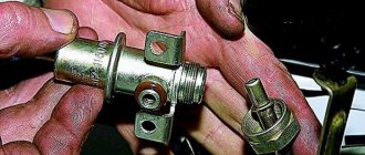
Fuel pressure control
Be careful when dismantling.
An RTD is a special device with a valve, assembled with a special diaphragm with a spring retainer. Under the influence of this element, the working position is in the locked type. It is also designed to divide the internal space of the regulator itself into two closed cavities - air and fuel.
The cavity for air is connected to the hose and receiver, and for fuel it is connected to the structure itself on the ramp.
During operation of the motor, the vacuum overcomes the resistance created by the spring and tries to tighten the diaphragm, thereby opening the valve. And from another position, at this time, gasoline presses on the diaphragm, also influencing the spring. As a result of this action, the valve opens slightly and part of the fuel flows back into the gas tank through the fuel line.
When the gas is pressed, the vacuum behind the throttle valve (throttle valve - approx.) becomes less, and the diaphragm, under the influence of a spring, closes the valve, increasing the fuel pressure. And if it is closed, the vacuum pulls the valve as far as possible - reducing fuel pressure.
The total pressure drop in the sensor is determined by the stiffness of the spring and the size of the hole. It cannot be adjusted, it is a non-separable element, and when it fails it must be replaced.
Fuel rail with injectors
An injector is a special solenoid valve that is needed to transfer gasoline to the manifold when current is applied to it, and close under the influence of a return spring when the power is turned off. They are mounted in place of fixation through special rubber rings and held there with a metal bracket. It is controlled by the ECU from the injection system. If a break or short circuit occurs in the injection wiring, the injectors should be replaced.
Injection system
An injection system in which feedback is provided and a fuel evaporation trap is installed. It consists of an adsorber, a separator, connection hoses and valves mounted under the hood. Its action is as follows:
- Some of the fuel vapor that accumulates in the tank is condensed in the separator and then drained back into the tank. And the rest pass through two-way and gravity valves.
- A two-way valve prevents excessive decrease and increase in pressure inside the fuel tank, and a gravity valve prevents fuel from leaking out when the vehicle rolls over.
Vapor recovery system
This is what the adsorber looks like on a VAZ-2112.
Afterwards, fuel vapors go through one fitting into the engine compartment - namely into the adsorber, where coal is installed to absorb them. The second fitting of the adsorber is connected to the throttle units using a tube, and the third is directly connected to the atmosphere. However, when the engine is not running, the 3rd fitting is closed by a valve and in this state the remaining elements are not associated with air. And when starting the engine, the controller of the system responsible for injection sends a signal to the valves with a frequency of 15-16 Hz , communicating the adsorber itself with the atmosphere. During such work, if the air flow rate is higher and the intensity of the pulses passes through more, then the blowing will be much more efficient.
And where this feedback does not exist, fuel vapors are “caught” only by a separator and one check valve.
VAZ-21124 engine control circuit
Connection diagram of the VAZ-21124 engine control system with distributed fuel injection under Euro-2 toxicity standards (controller M7.9.7): 1 - ignition coils; 2 — nozzles; 3 - controller; 4 - main relay; 5 - fuse connected to the main relay; 6 — cooling system electric fan relay; 7 - fuse connected to the cooling system electric fan relay; 8 - electric fuel pump relay; 9 - fuse connected to the electric fuel pump relay; 10 — mass flow and air temperature sensor; 11 — throttle position sensor; 12 — coolant temperature sensor; 13 — solenoid valve for purge of the adsorber; 14 — oxygen sensor; 15 — knock sensor; 16 — crankshaft position sensor; 17 — idle speed regulator; 18 — immobilizer control unit; 19 — immobilizer status indicator; 20 - phase sensor; 21 — vehicle speed sensor; 22 — electric fuel pump module with fuel level sensor; 23 — oil pressure warning lamp sensor; 24 — coolant temperature indicator sensor; A - block connected to the wiring harness of the ABS cabin group; B — diagnostic block; B - block connected to the air conditioner wiring harness; G - to the “+” terminal of the battery; D — to the side door wiring harness block; E - block connected to the instrument panel wiring harness; G1, G2 - grounding points; I - the order of conditional numbering of plugs in the block of the immobilizer control unit; II - the order of conditional numbering of contacts in the diagnostic block.
Connection diagram of the VAZ-21124 engine control system with distributed fuel injection under Euro-3 toxicity standards (controller M7.9.7): 1 - ignition coils; 2 — nozzles; 3 - controller; 4 - main relay; 5 - fuse connected to the main relay; 6 — cooling system electric fan relay; 7 - fuse connected to the cooling system electric fan relay; 8 - electric fuel pump relay; 9 - fuse connected to the electric fuel pump relay; 10 — mass flow and air temperature sensor; 11 — rough road sensor; 12 — throttle position sensor; 13 — coolant temperature sensor; 14 — idle speed regulator; 15 — control oxygen sensor; 16 — diagnostic oxygen sensor; 17 — solenoid valve for purge of the adsorber; 18 — knock sensor; 19 — crankshaft position sensor; 20 — immobilizer control unit; 21 — immobilizer status indicator; 22 - phase sensor; 23 — vehicle speed sensor; 24 — electric fuel pump module with fuel level sensor; 25 — oil pressure warning lamp sensor; 26 — coolant temperature indicator sensor; A - block connected to the wiring harness of the ABS cabin group; B — diagnostic block; B - block connected to the air conditioner wiring harness; G - to the “+” terminal of the battery; D — to the side door wiring harness block; E - block connected to the instrument panel wiring harness; G1, G2 - grounding points; I - the order of conditional numbering of plugs in the block of the immobilizer control unit; II - the order of conditional numbering of contacts in the diagnostic block.
Repair manual for VAZ 2110, 2112, 2111 (Lada 110)
The power supply system includes elements of the following systems:
– a fuel supply system, including a fuel tank, a fuel pump, a pressure regulator, a fuel filter, a ramp with injectors, hoses and pipelines;
– an air supply system, which includes an air filter, an air supply pipe, a throttle assembly;
– a fuel vapor recovery system consisting of an adsorber and connecting pipelines.
The functional purpose of the fuel supply system is to ensure the supply of the required amount of fuel in all operating modes.
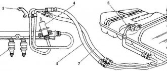
4.17. Engine fuel supply system mod. 2111 and 2112: 1 – fitting plug for monitoring fuel pressure; 2 – injector ramp; 3 – bracket for fastening fuel pipes; 4 – fuel pressure regulator; 5 – fuel pump; 6 – fuel filter; 7 – fuel drain line; 8 – fuel supply line; 9 – nozzles
Design of the motor power supply system mod. 2111 and 2112 (Fig. 4.17) differs from the power supply system for mod. 21114 and 21124 (Fig. 4.18) in that the latter do not have a return fuel line, since the pressure regulator is installed directly in the gas tank in the fuel pump module. In addition, for connecting elements of the fuel line on engines mod. 21114 and 21124 use special clamping tips instead of threaded fittings, the shape and design of the fuel rail are changed, new injectors are used, and the pressure is increased.
4.18. Engine fuel supply system mod. 21114 and 21124: 1 – fitting plug for monitoring fuel pressure; 2 – injector ramp; 3 – fuel pump module; 4 – fuel filter; 5 – tee; 6 – fuel supply line; 7 – nozzles
How to replace the fuel pump on a VAZ 2110 with your own hands - step-by-step instructions
In order to replace the fuel pump on a VAZ 2110, you must perform the following procedure:
- Disconnect the negative battery terminal;
- Relieve the residual pressure in the fuel rail using a special fitting;
The “tens” fuel pump is located under the rear seat of the car. We recline the seat and unscrew the protective cover;
Disconnect the electrical terminal block of the pump, unscrew the fuel supply and drain lines.
The rubber gaskets for the tips of the lines should be replaced;
On a VAZ 2112, the fuel pump is held in place by eight bolts on an O-ring with a lining
All you have to do is remove the old fuel pump and install a new one according to the indicating arrow on the body of the product.