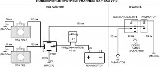
Every driver knows how tiring the yellowness of conventional incandescent lamps in car headlights can sometimes be. It is not advisable to install xenon lamps, although they have low consumption and a long service life. Due to the strong blinding of drivers of oncoming traffic, the likelihood of accidents increases. Halogen lamps provide a good and not excessively white glow.
Their main disadvantage is increased energy consumption and heat generation. In addition, like all incandescent lamps, their service life is half that of xenon lamps.
The physics of the filament burnout process is simple. When heated, any conductor increases resistance to passing current. The filament heats up in operating mode and provides the necessary glow power. At the same time, its resistance ensures that the current in the circuit is insufficient to melt the metal of the thread. When turned on, the resistance of a cold lamp is 12–13 times less than the working one and, accordingly, the electric current is the same number of times. It is at this moment that the filament most often burns out.
Ideally, it would be to gradually increase the voltage following warming up and, accordingly, an increase in resistance. This idea is not new - electronic devices have long been used in household lamps to ensure smooth switching on and extend the life of incandescent lamps. Examples of circuits of such devices can be found in large quantities on the Internet. When using them for a car, you need to take into account that it is better to use a replacement of a standard replacement part with a completely new one without the need to alter the main wiring.
This idea was implemented on a KIA Cerato LD car produced in 2008 with Philips CrystalVision H4 halogen lamps by simply replacing the standard low beam control relay with a modified analogue in accordance with the new requirements.
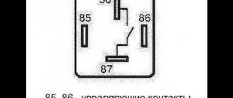
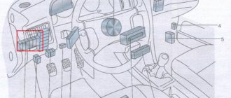
The headlight control diagram with some simplification is shown in the figure.
The easily removable relay is highlighted in red, which requires improvement. It is convenient that through contact “30” there is always +12 V power, and through “86” and the light switch or through “87” and cold lamps, with almost zero resistance, there is always a connection to ground.
The technical requirements were put forward as follows:
• consumption of the electronic relay when the ignition is turned off is within 5–7 mA, providing a small leakage current to protect the battery from discharge; • when the headlights are turned on for the first time, smooth heating of the lamp filaments should be ensured for 10–12 seconds; • when the light is turned off for less than 0.5 seconds. and then turning it on, if the ignition was not turned off, the delay should be 0.5 seconds. with output at 80% power plus 1 sec. to achieve 100% glow level; • with the engine on 0.5 sec. 50% low beam power is maintained after it is turned off.
The last point requires clarification. The glass bulbs of model H4 lamps combine low and high beam spirals. In this case, the car's wiring diagram is designed in such a way that they can only be switched on alternately. After the first switching on, the entire structure is maintained in a sufficiently hot state and a long delay for heating the threads is no longer required. This is important when the high beams flash briefly. After it, the low beam will turn on without delay and will not create inconvenience to traffic in the dark.
Introduction
My car, Kia Cerato LD (2008), has halogen headlights. I have no desire to blind oncoming drivers with the collective farm-installed xenon, but the white light of the headlights, it seems to me, is much more pleasing to the eye than the tiring yellowness of a “regular” lamp. I prefer Philips CrystalVision halogen lamps, which produce a white beam of light with other parameters the same as that of a “regular” lamp - that is, oncoming drivers are not dazzled if the headlight is adjusted correctly. You have to pay for such comfort: not only are they much more expensive than conventional headlights, but their lifespan is not very long. I noticed that the moment of burnout usually coincides with the moment the headlights turn on. And indeed: the greatest load on the thread falls at the moment when, from the street temperature, it has to heat up to several thousand degrees in a fraction of a second.
The resistance of the lamp filament depends on its temperature. Thus, the resistance of a cold filament can be 12-13 times lower than in operating mode; accordingly, at the moment of switching on, a current 12-13 times higher than the rated current flows through a cold lamp, which also entails an increase in power dissipation. This moment becomes disastrous for the lamp. What if you slow down the heating of the filament? - I thought. If you extend the heating time of the filament for a few seconds, perhaps this will increase its service life?
The idea of smoothly turning on the light is not new: with the help of a powerful field-effect transistor and a pulse-width modulator, this task has been implemented more than once, and there are a dozen different circuit options on the Internet. What they all have in common is that they require modifications to the wiring of the car itself. But is it possible to assemble such a circuit in the housing of a standard relay? Then the entire installation on the car would consist of simply replacing the relay, without the need to disturb the insides of the car. The problem seemed interesting to me and I started...
Smooth ignition of car headlights
In addition to the aesthetic pleasures of the gradual lighting of the headlights, the ignition circuit also has practical value for lamps. There will be no sudden voltage surges on the lamps, which will increase its service life and protect against unwanted burnouts. To implement a smooth ignition circuit for car headlights, the most important element will be a field-effect transistor.
You need to take a fairly powerful transistor designed for currents up to 25 A. Naturally, the transistor will need to be installed on a heat sink, it will heat up decently.
The circuit can also be used for LED lamps or strips, then such a powerful transistor is not needed, but we will still consider the circuit for powerful incandescent lamps, because
it is valid in any case, regardless of what light source is on the load.
When setting the values shown in the diagram, the time to turn on/off the headlights will be approximately 3-4 seconds.
The delay time is set by an RC circuit (in the diagram there is a 51 kOhm resistor and a 220 µF capacitor). You can experiment with the resistor value, choosing the turn-on and decay time you need.
The smaller the resistor value, the faster the capacitor will charge/discharge.
- The field-effect transistor was used brand IRF9540; as a bipolar transistor that controls the switching on of the field switch, you can take S9014 or the domestic analogue KT3102.
Please note that the capacitor is polar, incorrect polarity applied to the electrolyte will immediately explode it, be careful. A power of 0.25 W is enough for all resistors in the circuit. Before installing it in your car, be sure to experiment with how long the on/off time is. If the values are set incorrectly, the delay time can extend to a couple of minutes.
Source: https://xn—-7sbgjfsnhxbk7a.xn--p1ai/plavnyj-rozzhig-avtomobilnyx-far
Scheme requirements
After thinking a little about how it would look in operation, I came up with the following requirements that the circuit should satisfy:
1) Consume as little current as possible when the ignition is turned off. Although consumption in the region of 5-7 milliamps, which are required to power the stabilizer and microcontroller, would be acceptable, I would like to minimize the leakage current.
2) Ensure smooth heating of the lamp filaments for 10-12 seconds when first turned on. When the machine is just started, the thread should heat up smoothly.
3) If the ignition was not turned off, then after turning on the low beam again, it will quickly reach the 80% level within 0.5 seconds and then, within a second, reach the 100% level. Since H4 lamps are used, that is, combining low and high beam filaments in one bulb, when the high beam is turned on or blinking, the low beam is turned off. After turning off the high beam, the headlights remain quite hot and rapid heating does not greatly affect their operation. At the same time, waiting a few seconds for them to light up, as at the first start, is unacceptable: in traffic conditions, the road must be illuminated.
4) With the ignition on and the low beams off, hold the level at 50% for 0.5 seconds. This will prevent the filament from cooling during short flashes of the high beam.
Automatic switching on of headlights upon ignition
In order to organize such operation of the lighting elements, it is necessary to connect them to the ignition power source, and as many know, some devices can be connected at any position of the ignition switch, while others begin to function only when the ignition is already on. Based on this, the most convenient place to connect the headlights is the heater switch button (the rightmost switch block).
For this scheme you will need:
- any standard five-pin relay;
- diode;
- wires.
Next, we need:
- Remove the size switch (switch block on the leftmost side).
- Disconnect the positive wire from the key block responsible for the low beam operation (usually this is a green double wire) and connect it to the relay.
- You need to insert an additional wire into the positive wire that goes to the heater switch and also connect it to the relay.
- Connect the wire that powers the headlights to the relay.
- Throw the wiring to minus (to the body).
Diagram for connecting the standard relay
| Simplified diagram for switching on the low beam relay on a Kia Cerato LD |
Let's look at the relay connection diagram.
The circuit is quite simple: the switch on one side, the ignition on the other - they control the relay winding. That is, the light turns off both when the switch is turned and when the ignition is turned off.
The switch is the only source of constant “minus” in this diagram. But according to the above requirements, after turning off, the circuit must “remember” that the ignition was not turned off in order to quickly return the low beam when it is needed. Little of! The circuit must maintain the filaments at full heat after the low beam switch is turned off.
However, the source of the “minus” can be the headlights themselves, whose resistance is quite low. The solution is to use parasitic power through the headlight circuit. If you install a capacitor of sufficient capacity so that it can hold power to the control microcontroller while it switches to pulse width modulation (PWM) mode, then it can be recharged when the switch is open.
Automatic headlight switch with delay | Homemade catalog
To comply with the requirements of the new traffic rules changes, you should turn on the low beams on your vehicle when driving on a country highway, even during the day. In the city, you also need to remember to turn on the lights in conditions of poor visibility.
Except for compulsory cases imposed by law, each driver has the right to decide when to protect himself and others. It is recommended to turn on the lights on your car when driving through a section of road near kindergartens, schools, and playgrounds. Any vehicle, especially a gray, black, white body color, becomes many times more noticeable when the head lights are turned on.
On a clear day, when the sun makes you close your eyes, there is no reason to reach for the headlight switch. It’s another matter when automation remembers important things for you. And in order for the automatic light switch circuit to only please you and not be thrown out of the car soon, several conditions must be met:
- The headlights should light up with a delay of 10–15 seconds after starting the engine. This is necessary so that there is no large voltage drop when a powerful lighting load and starter are operating simultaneously.
- The headlights should turn off with a delay (the time must be selected individually) after the engine is turned off. This is important so that the lights do not click again if you need to turn off the car near a crossing or for quick refueling. Homemade DRL control unit .
- Electronics must operate at relatively high currents . So it is necessary that neither humidity nor temperature, which varies widely inside the car, greatly influence the operation of the elements of the automatic headlight switching circuit.
- So, this simple scheme has been tested for a long time and is successfully used:
- Instead of the above elements, you can use others:
- The K561LA7 microcircuit can be replaced with K561LE5, CD4001, CD4011. The input logic does not matter at all, since only the inversion of the outputs is used.
- Diodes KD522 - on KD521, KD105, 1N4148.
- Transistor KT815A - on KT817, KT604.
- All capacitors must be selected for a voltage of 25 V.
Well, or try another, easier to assemble, smooth ignition device .
Power connection
- It is important to connect the anode of the VD1 diode to the output of the ACC ignition switch, from which voltage is supplied to the ignition or injector switching circuit. But not to the starter switching terminal, since in this case the headlights either will not turn on at all or will go out immediately after starting the engine.
- The microcircuit is powered directly from the battery (+Acc, -Acc), and not from a circuit that is switched off.
- The open contacts of a standard automotive relay K1 are connected to the break in the wire running from the power circuit to the low beam contacts of the headlights.
Setting up the scheme
The delay time for turning on the headlights can be set to more than 10–15 seconds by selecting resistor R2 with a higher resistance.
If desired, the delay time for turning off the headlights can be reduced (according to this scheme it is 5–10 minutes) by installing resistor R1 of lower resistance.
Changing the delay time by replacing capacitor C1 is undesirable, since such an element with an unusually high capacitance (used in the circuit at 2200 μF) is necessary to deliver a relatively high current.
If you use a small capacitor in the driving circuit, you would have to install megaohm resistors R1, R2, which are not stable due to high leakage currents.
Conversion to 24 volts
- Take all capacitors of the same capacity, but for a voltage of 50 V.
- Change resistor R3 to another 300 Ohm.
- It is advisable to install a 5 volt zener diode between pins 7 and 14 of the microcircuit.
- And don’t forget to replace the relay with a 24-volt one.
Source: https://volt-index.ru/electronika-dlya-nachinayushih/interesnoe/avtomaticheskiy-vklyuchatel-sveta-far-s-zaderzhkoy.html
Electronic relay circuit
As a result, the following scheme was born:
| Electronic relay circuit |
Components used
| On the diagram | Denomination | Frame | Description | |
| ATtiny13A | ATtiny13A-SSU | soic-8 | Control microcontroller | |
| 79L05 | MC79L05ACD | soic-8 | Stabilizer -5V, 100mA | |
| VD1, VD2, VD3, VD4 | BAS321 | sod323 | diode 200V, 250mA, 50ns | |
| R1, R7, R9, R12 | 20kOhm | 0805 | resistors 5%, 0.125W | |
| R2 | 10kOhm | 0805 | resistor 5%, 0.125W | |
| R3, R5, R10 | 51kOhm | 0805 | resistors 5%, 0.125W | |
| R4, R6 | 51 Ohm | 0805 | resistors 5%, 0.125W | |
| R8 | 5.1kOhm | 0805 | resistor 5%, 0.125W | |
| R11 | 130 Ohm | 0805 | resistor 5%, 0.125W | |
| C1 | 22uF | D | tantalum capacitor, 35 Volt | |
| C2 | 2.2uF | 1206 | ceramic capacitor X7R | |
| VT1 | IRLML0030 | sot23 | MOSFET, n-channel, 30V, 5.2A | |
| VT2 | 2N7002 | sot23 | MOSFET, n-channel, 60V, 115mA | |
| VT3 | IRLML5103 | sot23 | MOSFET, p-channel, -30V, -0.76A | |
| VT4 | IRF9310 | soic-8 | power MOSFET transistor, p-channel, -30V, -20A, RDS(on) | |
Description of the electronic part
The relay is connected to the car's electrical system as shown in the figure.
The main power element is a MOSFET with a p-channel VT4. The main requirement for it is to provide direct current switching of at least 12 Amperes, while withstanding pulse current up to 150 Amperes; it should have a low source-drain resistance in the on-state, but at the same time a moderate input capacitance, and open at a source-gate voltage of 5 Volts. IRF9310 was chosen as such; it is designed for drain-source voltage up to 30V and current up to 20A (up to 16A at a temperature of 70 degrees), pulse current up to 160 Amperes. At a source-gate voltage of 4.5 Volts, it provides a source-drain resistance of no more than 6.8 mOhm, and an input capacitance of 5.2 nF.
It is controlled by an ATtiny13A microcontroller operating at a frequency of 1.2 MHz, consuming less than a milliampere of current in this mode. Its power drivers are capable of receiving and delivering current up to 40mA, which is quite enough to control the gate of a power transistor. The PWM output of the microcontroller, operating at a frequency of 2.35 kHz, is connected to the gate of the transistor through a 130 Ohm resistor R11, which, taking into account the gate resistance, as well as the voltage drop under load at the microcontroller pin, limits the current to 33-35 mA. Fast closing of the transistor is also ensured by discharge of the gate through the microcontroller pin, but when the circuit is turned off, the 20kOhm resistor R12 keeps the transistor closed.
Power is supplied through a linear stabilizer 79L05 negative voltage -5V designed for a load of up to 100mA. In this circuit, it is the main current consumer: the quiescent current in it can reach 6 mA. Current ripples caused by the charging moments of the transistor's gate are smoothed out by a ceramic capacitor C2 with a capacity of 2.2 μF (you can use 1 μF).
The only permanent negative wire comes through the low beam switch. The circuit should continue to work at full heat even after turning off the low beam, and also actively monitor whether the ignition has been turned off. The solution to this is to use parasitic power through the lamps themselves. At the moment when the MOS transistor VT4 is closed, capacitor C1 is charged through the headlights and diode VD3, providing power to the circuit for at least 10 ms. The circuit uses a 22uF tantalum electrolytic capacitor, but the circuit will work using a 10uF capacitor. The capacitor must be designed for a voltage of at least 35 Volts. Resistor R4 51 Ohm limits the current in the circuit when the capacitor is discharged.
When the low beam switch is turned on, the circuit is powered through it and the diode VD4, an additional 51 Ohm resistor R6 is also designed to limit the capacitor charge current flowing through the closing contacts of the low beam switch. The diodes chosen were BAS321, designed for a direct current of 250 mA, a pulsed (within 10 ms) current of up to 1.7 A, with a breakdown voltage of 200 Volts.
Transistor VT1 disconnects the circuit from power when the ignition is turned off. The chosen n-channel MOS transistor IRLML0030 is designed for a current of up to 5 Amps and allows a voltage between gate and source of up to 20 Volts. Instead, another transistor can be used, rated for a current of up to 1 Ampere.
When voltage appears on the ignition line, a current flows to the gate of the transistor through diode VD1 and resistor R1, as well as headlights, diode VD3 and resistor R4 20 kOhm, which charges the gate and opens the transistor. When the voltage on the ignition line disappears, the gate is discharged through the 50 kOhm resistor R3. If, while the ignition is on and the power transistor VT4 is open, the low beam switch opens, then the charge of the capacitor C1 through the diode built into the transistor V1 itself continues to maintain the potential difference between the gate and source of the transistor, thereby preventing it from closing until the microcontroller will not go into pulse mode, which will allow the capacitor to be recharged through the headlights.
At the same time, the input from the ignition through the diode VD2 and the 10 kOhm resistor R2 opens the n-channel MOS transistor VT2. It connects the PB4 pin of the microcontroller to microcontroller ground. This pin is connected to the power line through a pull-up resistor built into the microcontroller (about 40 kOhm). The current passing through transistor VT2 is quite small, about 125 μA, but since its source is connected to the -5V line, an important parameter for its selection should be a small threshold gate voltage. The choice fell on 2N7002, whose threshold voltage does not exceed 2.5 V. Taking into account the fact that there may already be a small potential difference between pins 85 and 30 of the relay, resistor R2 and diode VD2 were chosen to minimize the voltage drop. The same BAS321 is used as a diode; at low currents, the voltage drop across it is about 0.7 Volts. When the ignition is turned off, the gate of transistor VT2 is discharged through the 50 kOhm resistor R5, the voltage at pin PB4 increases through the built-in pull-up resistor, thereby notifying the microcontroller that the ignition is turned off. In the few milliseconds provided by capacitor C1, the microcontroller manages to discharge the gate of power transistor VT4 and go into standby mode.
Resistor R7 20kOhm pulls the PB3 input of the microcontroller to the -5V line, thereby keeping the logic level at the input low. When the low beam is turned on, the gate of p-channel MOS transistor VT3, for which IRLML5103 is selected, is charged through resistor R9 20 kOhm, which attracts pin PB3 to the power line and sets the logic level high. When the low beam is turned off, the gate of transistor VT3 is discharged through resistor R10 50 kOhm, and a low logic level is set at the input PB3 of the microcontroller through resistor R7, notifying the microcontroller that the headlight switch is turned off. At this moment, if power transistor VT4 is open, then capacitor C1 is not charged, but its charge is enough for the microcontroller to switch to PWM control of the power transistor, thereby allowing the capacitor to recharge through the headlights.
AVR microcontrollers have a built-in pull-up resistor on the reset pin. But in order to ensure stability of operation in conditions of possible interference, an additional pull-up resistor R8 5.1 kOhm was added to the circuit.
Operating modes
So, how does the circuit behave under different modes?
The ignition and lights are turned off.
Transistors VT4 and VT1 are closed. With the exception of leakage currents in transistors, no current flows within a few microamps.
Ignition is on.
Through diode VD1 and resistor R1, resistor R4 and diode VD3, transistor VT1 opens, capacitor C1 is charged, the 79L05 stabilizer is turned on, and power is supplied to the microcontroller. Through diode VD2 and resistor R2, transistor VT2 opens, which puts the PB4 input of the microcontroller to ground, which notifies that the ignition is on. The microcontroller waits for the headlights to turn on.
Low beam is on.
Through resistor R9, transistor VT3 opens and connects the PB3 input of the microcontroller to the power line, which notifies it that the headlights are turned on. The capacitor is kept charged through the diode VD4. The controller controls the power transistor VT4.
Low beam is off.
Transistor VT3 is closed by resistor R10 and the microcontroller turns on PWM mode to control the power transistor. In the intervals when transistor VT4 is closed, capacitor C1 is recharged through the headlights and diode VD3. At the moments when VT4 is open, VT1 is held open because the charge present on C1 goes to the source of transistor VT1 through the built-in diode.
Ignition is turned off.
Transistor VT2 closes through resistor R5, through the pull-up resistor built into the microcontroller, a high level appears at input PB4, detecting which the microcontroller closes VT4 and goes into standby mode.
At the same time, transistor VT1 closes through resistor R3, disconnecting the capacitor from the headlights and light switch.
The ignition is off but the low beam switch is on.
In this case, transistors VT1 and VT4 are also closed, but an additional 170 microamps flow through resistors R9 and R10 (at a voltage of 12 Volts)
Heat dissipation
The specification for the IRF9310 power transistor says that at a gate-source voltage of -4.5 Volts, the source-drain resistance will be a maximum of 6.8 mOhm. Based on the margin that the headlights consume 11A, the power dissipated by the transistor will be a maximum of 0.822 watts. That is, the body will heat up by 16.5 degrees relative to the legs. The task is to effectively remove heat from the soldering site of the transistor. The specification indicates that even when soldering 1 square inch (25.4 x 25.4 mm square) of copper, 35 microns thick, the temperature increase will be 50 degrees per watt, i.e. 41 degrees in our case. Although it will not be possible to place such a cooling pad in a small relay case, heat can be removed outside through the relay leg by soldering the drain of the transistor as close as possible to the place where the leg is attached.
An experiment at room temperature showed that although the transistor heats up, you can hold your finger on it for a few seconds. That is, its temperature is about 55-60 degrees, which is 30-35 degrees more than room temperature. The level is quite acceptable.
The nuances of turning on running lights
The basic requirements regarding installation, technical parameters and connection of navigation lights are listed in paragraph 6.19 of GOST R 41.48-2004.
In particular, the electrical functional circuit of the DRL must be assembled in such a way that the running lights turn on automatically when the ignition key is turned (the engine starts).
In this case, they should automatically turn off if the headlights are turned on.
Clause 5.12 of this standard states that headlights (FGS) should be turned on only after the lights are turned on, with the exception of short-term warning signals. When connecting DRLs yourself, this feature must be taken into account.
Correct connection of DRLs is not limited to a well-thought-out functional diagram. It's time to think about the stabilization unit for LEDs. In the running lights themselves, resistors act as a current limiter; however, due to voltage drops, resistors cannot limit the current to the same level.
That is why a voltage stabilizer in the running lights connection circuit is extremely necessary. Otherwise, the service life of LED DRL modules is significantly reduced due to constant changes in on-board voltage. Some car enthusiasts claim that it is possible to connect running lights without a stabilizer.
Connecting and installing an LED driver is a waste of time, because the DRLs on LEDs shine regularly for months without any stabilization...
However, this statement is easy to dispute.
The fact is that with each voltage surge, more than 12 V appears on the LED module, the forward current through the LEDs exceeds the nominal value, which leads to overheating of the emitting crystal.
The brightness of the LEDs decreases, such DRLs will no longer be able to fulfill their immediate task - to warn oncoming drivers from afar, and over time they will begin to flicker and fail.
Using LED DRLs without a voltage stabilizer means spending at least several hundred rubles every year on new modules and wasting time replacing them.
Switching on through dimensions or low beam
This circuit solution has several disadvantages:
- running lights remain on when the engine is turned off, which is contrary to current regulations;
- the circuit will not work if LEDs are also installed in the dimensions;
- the circuit will not work correctly if the DRLs contain powerful SMD LEDs, the rated current of which is comparable to the current of a light bulb;
- For safety reasons, an additional fuse must be installed.
When parking a car at night, side lights are used to indicate it; the use of DRLs is prohibited.
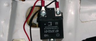
Connection via a 4-pin relay from a generator or oil sensor
- 30 – to the positive terminals of LED modules;
- 85 – to the positive wire to the dimensions;
- 86 – to any reed switch output;
- 87 and the second terminal of the reed switch - to the “+” of the battery.
After checking the reliability of all contacts, proceed to setup. To do this, start the engine and, by moving the reed switch near the generator, achieve its activation and a stable glow of the DRL. Then the reed switch is hidden in a thermal tube and fixed in the found place using nylon ties.
At the moment of starting the engine, and then the generator, the contacts of the reed switch and relay close, supplying power to the LED running lights. In this case, the side lamps remain turned off, since the current through the relay coil is small to light them.
Connection via 5-pin relay
- 30 – to the positive terminals of LED modules;
- 85 – to the positive wire of the side lamp;
- 86 – on the car body;
- 87a – to “+” from the ignition switch;
- 87 – do not connect (isolate).
The circuit with a five-contact relay works as follows. When you turn the key, +12 V is supplied to the DRLs, thereby turning them on. If you turn on the side lights or headlights, the relay will open contact 87a and close inactive contact 87. As a result, the DRLs will go out and the side lights will turn on. The circuit fully complies with the requirements of GOST and traffic regulations and can work with side lights even based on LEDs.
However, the circuit still has one negative point - the DRLs will turn on immediately after turning the ignition switch. That is, if you turn the key in the ignition but do not start the car, the DRLs will light up.
Despite the existing drawback, the circuit is quite successful, but in order to correctly connect the DRL via a five-pin relay, you will need to supplement the circuit with a voltage stabilizer.
This switching option is interesting because the path of current flow through the running lights is independent. This allows you to install light sources of any type and power in headlights and DRLs.
DRL control unit
The most reliable and simplest option is to connect DRLs without a relay, but using a special running lights control unit. It ensures that the DRL turns on after starting the engine, guarantees safe operation, protects against overloads and can be installed on cars with any type of lamps, including LEDs.
Unfortunately, among the variety of industrially manufactured DRL units, the vast majority do not comply with GOST and have mediocre build quality.
This applies, first of all, to products from AliExpress, which do not meet the requirements in almost all respects.
Among all the diversity, only 2 options can be noted: the Russian DayLight+ DRL control unit and German products from Philips and Osram. The DayLight+ control unit was developed by Russian radio engineer Fedor Isachenkov, taking into account all the features of the vehicle’s on-board network and has a number of positive aspects:
- there is built-in voltage stabilization;
- full compliance with GOST;
- the maximum long-term load power is 36 Watts (significantly less is required for DRLs);
- simplest connection diagram.
Source: https://ledjournal.info/shemy/podklyuchenie-dnevnykh-khodovykh-ogney.html
Work algorithm
| Slow warm-up |
If the ignition was turned off, then when the headlights are turned on for the first time, a slow warm-up occurs:
— within 3 seconds, the PWM duty cycle smoothly increases to 30%;
— then, for 2 seconds, it remains at the same level, allowing the lamps to gradually increase temperature;
- then, within 3 seconds it increases to 80%, giving an acceptable level of illumination;
- and finally, within 4 seconds it is brought to 100%.
| Hold after shutdown |
When the headlights are turned off, the PWM duty cycle is immediately set to 50%, allowing the capacitor to charge.
— It is held at this level for 0.5 seconds;
- and then smoothly decreases to zero within 0.5 seconds.
If the ignition was not turned off, then when the headlights are turned on again, a rapid warm-up occurs:
— within 0.5 seconds the level increases to 80%;
- and then within 1 second it is brought to 100%.
| Quick warm-up |
If the headlights were turned off during slow warm-up, then:
— if the level has reached 50%, then the transition to the holding phase occurs.
— if the level is less than 50%, then the light turns off, and the next time the headlights are turned on will be considered the first, and a smooth warm-up will be performed.
If the headlights were turned off during rapid warm-up, then:
— if the level is greater than or equal to 50%, then the transition to the holding phase occurs
— if the level is less than 50%, then the transition to the holding phase is carried out to the position of the falling part that corresponds to the current level. In other words, there is a smooth attenuation without a half-second hold.
If the headlights were turned on again during the hold phase, a transition to the fast warm-up phase is carried out, to a point on the graph whose level corresponds to the current PWM duty cycle.
Main conclusions
Smooth ignition of LED-based lamps is popular in automatic lighting. In addition, the slow switching on of the ice elements allows you to extend their service life, regardless of the installation location. You can buy such a device or make it yourself. In the latter case, it will cost much less. For assembly you will need the following materials and tools:
- Soldering iron with soldering accessories.
- The basis for the board, for example, a piece of PCB.
- Housing for fastening elements.
- Resistors, transistors, diodes, capacitors and other semiconductor elements.
The mechanism of the soft ignition device for LEDs works on the principle of delay that occurs in the resistor-capacitor circuit.
In this case, there are two main schemes - the simplest and with the ability to adjust the ignition time. The latter differs from the first by the presence of two resistors with controlled resistance. The higher its value, the longer the slow start period, and vice versa. No tags for this post.
Microcontroller program
The program implements a finite state machine that is in one of six states:
— the ignition was turned off, waiting for the headlights to turn on.
- smooth warm-up
— the light has already turned on, waiting for the headlights to turn on again
- quick warm-up
— lamp is on 100%
— holding and extinguishing after turning off the headlights.
PWM is implemented using the “phase-correct PWM” timer mode operating at the processor frequency. This mode provides full shutdown and full turn on at extreme values of the PWM parameter, and one period takes 510 processor cycles. When the microcontroller operates at a frequency of 1.2 MHz, the pulse frequency is 2353 Hz.
State machine states are processed in the timer overflow interrupt handler.
// Timer interrupt, executed 2353 times per second ISR(TIM0_OVF_vect) { if (countdown > 0) { countdown—; return; } switch (current_state) { case STATE_SLOW_WARM: { // slow warm-up uint8_t o = PWM_OC; if (o >= 254) { PWM_OC = 255; current_state = STATE_ON; } else { o++; PWM_OC = o; if (o < SLOW_RAMP_VALUE) { countdown = SLOW_RAMP_SPEED; } else if (o == SLOW_RAMP_VALUE) { countdown = SLOW_RAMP_HOLD; } else if (o < SLOW_WARM_VALUE) { countdown = SLOW_WARM_SPEED; } else { countdown = SLOW_LAST_SPEED; } } } break; case STATE_FAST_WARM: { // fast warm-up uint8_t o = PWM_OC; if (o >= 254) { PWM_OC = 255; current_state = STATE_ON; } else { o++; PWM_OC = o; if (o < FAST_WARM_VALUE) { countdown = FAST_WARM_SPEED; } else { countdown = FAST_LAST_SPEED; } } } break; case STATE_HOLD: { // hold after disconnect uint8_t o = PWM_OC; if (o <= 1) { PWM_OC = 0; current_state = STATE_LIGHT_OFF; } else { o—; PWM_OC = o; countdown = HOLD_FALL_SPEED; } } break; } }
There is also an interrupt that monitors changes in logic levels at inputs PB3 and PB4. If such a change is registered, regardless of which input, the state of both inputs is evaluated, and depending on this and the current state, the machine is transferred to one state or another.
// Interrupt for any change in logical levels at the “ignition” and “light switch” inputs ISR(PCINT0_vect) { if (is_ignition_on()) { if (is_switch_on()) { // If the ignition is on and the switch is on. switch (current_state) { case STATE_IGNITION_OFF: current_state = STATE_SLOW_WARM; countdown = 0; break; case STATE_HOLD: case STATE_LIGHT_OFF: current_state = STATE_FAST_WARM; countdown = 0; break; } } else { // If the ignition is on, but the switch is off switch (current_state) { case STATE_SLOW_WARM: if (PWM_OC >= HOLD_VALUE) { PWM_OC = HOLD_VALUE; current_state = STATE_HOLD; countdown = HOLD_COUNTDOWN; } else { current_state = STATE_IGNITION_OFF; PWM_OC = 0; countdown = 0; } break; case STATE_FAST_WARM: current_state = STATE_HOLD; if (PWM_OC >= HOLD_VALUE) { PWM_OC = HOLD_VALUE; countdown = HOLD_COUNTDOWN; } else { countdown = 0; } break; case STATE_ON: PWM_OC = HOLD_VALUE; current_state = STATE_HOLD; countdown = HOLD_COUNTDOWN; break; } } } else { // If the ignition is off, then off, no options. current_state = STATE_IGNITION_OFF; PWM_OC = 0; } }
The main body of the program does not perform any actions, but simply cyclically puts the microcontroller into idle mode.
set_sleep_mode(SLEEP_MODE_IDLE); sleep_enable(); sei(); while(1) { sleep_cpu(); }
In the microcontroller settings, the voltage drop protection mode (Brown-out detector) is enabled and set to a level of 2.7 Volts. When the voltage drops below this level, the microcontroller enters a reset state.
The delay after reset is set to 64ms (default setting).
Set of functions IRIDIUM silent relay “Forget-me-not-5-12V”
– Function of smooth ignition of low beam lamps 3 sec . SILENT TURN ON ;
– Does not require intervention in electrical wiring;
– Start delay function 5 sec (programmable);
– The relay turns on DRL, low beam or PTF when the engine is started;
– 2 trigger voltage thresholds 13.3 V and 12.8 V (default 13.3);
– The relay closes the contacts according to a given program even if the low beam or DRL switch is OFF;
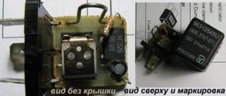
Relay manufacturing
| standard Kia relay |
As it turned out, Kia uses its own unique forms of relays, which you cannot find in shops on the street, only on order and for a lot of money. The relay is symmetrical four-legged: two diagonal legs are the coil, the other two legs are closed contacts. In general, this is convenient: you don’t need to think about which side to plug into the steering wheel, it will work either way. But in our case, maintaining polarity plays an important role; if you turn the relay the wrong way, this can lead to the power transistor burning out. Well, you will have to draw a warning notice on the case and be careful when installing.
| 95220-3A300 disassembled relay shunt for Kia |
But there was no need to disassemble the relay. As it turns out, my car has the option of daytime running lights. All you need to do is pull out the plug, which is shaped exactly like a relay, and insert a regular relay in its place. That's exactly what I did. I found this shunt plug in my hands.
Not only is such a shunt much more convenient for subsequent processing, but also when ordered, it will cost several times less than a whole relay.
| Prototype for experiments |
After some filing and finishing of the shunt, I began designing a board that would fit into this case. There is not much space inside: the board should not exceed 19mm in width and 18mm in height. The board had to be made double-sided. The sides are connected to each other at four points. To connect, I used pieces of legs left over from radio components.
For etching I used Laser Ironing Technology (LIT), printing the template on a laser printer on glossy photo paper for inkjet printing.
|
|
| ||||||||
|
|
| ||||||||
|
| |||||||||
DIY connection
First of all, it must be said that having disassembled the dimmer, everyone can understand that its connection is no more complicated than a regular switch.
Let's create step-by-step instructions, using which everyone can get the desired result:
The first and most important step is to disconnect the power from the outlet.
This is a safety measure, because you need to work with exposed wires, and getting hit by 220V is not the most pleasant thing.
Loosen the screws on the terminals.
Next, we connect 2 wires of the switch to the wires from the old switch (it is important not to forget and observe the polarity, otherwise, at best, everything will have to be redone).
We remove the top frame and install the device in a specially designated place in the wall.
Screw in the screws of the mounting tabs.
We fasten the top frame (box).