In this article we will learn how to change the colors of the button illumination on the instrument panel of the VAZ 2110. The explanation will be given using the example of the button for turning on the rear fog light. First of all, you need to dismantle this very button and disassemble it. To achieve this, we pull its body and moving part in different directions. After the button has been pulled out from its regular place, we get free access to the incandescent lamp in the housing.
Here a lot depends on your dexterity. If you wish, you can remove it at this stage of tuning the VAZ 2110. If you can’t remove the light bulb, then we continue disassembling further. Use a thin screwdriver or knife to pry up the latches on both sides. So, here we have the switch mechanism. We need a black staple. We pry it off with the same screwdriver and then the whole mechanism will fall apart. Now we can easily remove the lamp, for example, with tweezers, after wrapping it with insulating tape at the ends for better adhesion to the lamp. Or, between two contacts 6 and 7, we find a small hole and thread a thin needle through it in order to squeeze out the lamp. Now you can use your imagination and resources to work. You can buy an LED lamp of any color in a specialized store. In our case, we use the standard design. If you still decide to use LEDs, then keep in mind that the positive contact is number 6, and the negative one is number seven. We find out the polarity by looking at the back of the case, where the block with wires is inserted. We check whether the backlight is working. If everything is normal, then we move on to the second part of the work, which takes a little longer than the first.
Now we need to get rid of the green filter in the plastic with the fog light icon. You can remove it with a soldering iron, but in this case you need to act extremely carefully, and it is better to entrust this task to an experienced person. If you want to do everything yourself, then the smartest idea is to drill it out. This is done with a very thin 1 mm drill. We make the hole carefully so that the drill does not pierce through the entire structure. To determine the thickness, drill the first hole in thin layers until you see thin plastic. As a result, we remove the light filter from the structure and again check its functionality. Almost all buttons can be modified in this way; the only exception may be the position of the positive and negative contacts, which must be looked at according to the electrical diagram. If such a diagram is not at hand, then it can be found on the Internet. The negative contact in them is usually indicated by a black wire, but the positive contact can be of any color, but as a rule, it is white. If you want to change the color of the illumination of not only the buttons, but also the indicators of the instrument panel, you will have to disassemble it. In this case, the task becomes more complicated. Be careful with the latches, they often break and you have to buy new ones. Remember, or better yet, sketch or photograph all the contact connections so that there is no confusion during the assembly process. Assembly is carried out in reverse order.
In this article I will share my experience of changing the color of the key backlight on the instrument panel of a VAZ-2110. I will consider the principle on the rear fog light switch.
First of all, remove the key itself and disassemble it.
To do this, pull the body and the moving part to the sides. Then we will see the incandescent lamp in the housing.
Then it all depends on your dexterity: you can pull it out of there (I didn’t succeed). If the efforts do not produce results, we analyze further. To do this, use a screwdriver or a knife to pry off the latches on one side and the other.
The button mechanism opened before us.
Our target is a dark bracket; we pry it with a screwdriver and the mechanism falls apart.
This way we get the opportunity to freely pull out the lamp, for example, with tweezers with electrical tape on its ends for better adhesion to the lamp. Or between pins 6 and 7 there are tiny holes through which a needle can fit to squeeze out the lamp
It all depends on your imagination and means. For example, you can purchase a ready-made LED lamp of any color. I used my own design (1st experience of soldering SMD components).
We check the functionality, if everything is ok, we go to the 2nd part, which took a little more time than the 1st.
(In general, for the rest of the keys the process is similar, the only exception can be the position of the contacts + and , which must be looked at according to the diagram of the electrical equipment. These diagrams are available on the network, the negative contact is usually marked on them with a black wire, and the positive contact can be of any color, but usually it is marked in white).
Now we need to get rid of the greenish filter in the plastic with the anti-fog light pictogram. At first I tried using a soldering iron, but then I abandoned this idea. The most reasonable thing, in my opinion, is to drill it out, using a very narrow 1mm drill bit.
The hole must be made carefully so that the drill does not pierce through the entire structure. To determine the thickness, I drilled the first hole in thin layers until I saw snow-white plastic. As a result, having removed the light filter from the structure, we will assemble it and check its functionality.
Situations in which the instrument panel on a VAZ 2110 does not work are not at all uncommon for a product of the domestic automobile industry. Any car is not without sin, so car owners have no choice but to deal with the problems that arise over and over again.
Dashboard
Instrument panel VAZ 2112 - designations
The more modern the car, the more complex its design and the more difficult it is to control the condition of components and systems independently. For foreign-made cars, this issue has been resolved since the 80s by integrating on-board computers and other auxiliary devices into the car control system. Modern cars from Tolyatti are at the level of the 70s of the last century in terms of electronics equipment, and on-board computers can only display the time and temperature in front of the front bumper.
Designations
Despite such electronic asceticism, it is in principle possible to splurge on several dozen light bulbs and scales. Sitting at home, with a book in hand and drinking tea. But when, at a speed of 140, some indicator begins to frantically demand attention, you involuntarily get lost, and control over the car becomes, to put it mildly, not the most ideal.
Especially when you change from a penny to the wheel of a 2112, you feel like young Gagarin in an alien spaceship, when every light means something, and what exactly - go and figure it out. For these purposes alone, it was worth studying the new panel one hundred and twelfth in more detail, which we are happy to share.
Description
In order not to violate the informational nature of the panel description, and most importantly, so as not to redraw the arrows, we will use the factory layout of warning lamps and indicators on the instrument panel. Here she is.
- A pointer indicator that schematically shows the approximate temperature of the coolant in the cooling system. The pointer receives a signal from a sensor that is installed between the cylinder head and the thermostat, so it shows a more objective temperature. The device is divided into divisions with a value of 20 degrees. The sensor is able to recognize temperatures starting from 50 degrees, and unsafe temperature conditions begin in the red zone with a temperature of 105 degrees. The gradation ends at 130 degrees, at which the motor is almost guaranteed to overheat and jam.
- Tachometer. Shows engine revolutions per minute in real time. The tachometer scale has divisions of five units, and digitization is carried out every 10. By adding two zeros we get the real value. The red zone starts at 55 units.
- A llama with an arrow indicating which turn signal is on, in this case, the left one.
- Controlling the activation of the right turn signal.
- An induction speedometer receives data on the speed of the vehicle from a sensor located in the gearbox. The accuracy of the speedometer readings is not very high, and depending on the speed of movement, it may have an error of 5 km/h or more.
- Fuel level indicator. It receives a signal from a sensor located directly in the fuel tank.
- When the fuel level drops to critical, this warning lamp lights up.
- Low beam switch lamp.
- Brake fluid level warning lamp.
- High beam indicator.
- Clock adjustment knob.
- Odometer and daily mileage.
- Alarm.
- Critical engine failure caused by failure of electronic systems.
- Clock and thermometer.
- Low battery charging voltage.
- Handbrake warning indicator.
- Critical oil pressure.
- Fuel mixture enricher indicator.
Instrument panel for VAZ 2112 europanel. Installation instructions
You can talk about the advantages and disadvantages of this model for quite a long time. However, this is not what we are talking about now. Those who decide that the “ten” is a suitable option in terms of the ratio between price and quality often want to somewhat refine their iron horse during operation, making changes to both the exterior and the interior.
If we talk about tuning the car interior, then one of the main objects of improvement here is the dashboard. Many people simply don’t like the native version, which, frankly, doesn’t look very attractive. Yes, after the “Zhiguli” this is an undoubted step forward, but it’s already the 21st century outside the window, and I want something more beautiful and pleasing to the eye.
Why you should know the pinout
But before you start this kind of upgrade, you need to understand which wire leads where. The pinout of the instrument panel of a VAZ-2110 car is a very important point when “tuning”. Without this, you risk simply getting confused in a fairly large number of wires, buttons and various sensors. The pinout will be useful in any case - both when making minor improvements and when completely replacing the instrument panel.
The process of installation and dismantling itself is quite labor-intensive, but if you know the correct sequence of actions, then there is nothing particularly difficult about it.
For these works you will need a minimum set of tools - a screwdriver and pliers.
For those who are doing this for the first time, it is best to stock up on self-adhesive pieces of paper, like those on which prices are written in stores, and a pen. With their help, at the time of disassembly, you will indicate, firstly, the sequence of dismantling the parts, and secondly, which wire is connected where. At first glance, this may seem time-consuming, but in fact, for beginners, such markings will help them put the panel back together faster.
At the same time, before starting work, it is best to stock up on a pinout diagram - at least conditional. After all, during the work process you need not to confuse anything and correctly understand each wire and connection during the reassembly process. It is worth noting one very important point. By and large, understanding the pinout of the panel of the “tenth” family will not be difficult even for a beginner.
But you need to remember that there are certain differences here, depending on the plant where the car was manufactured and the year of its manufacture. For example, the instrument panel may be an old model, with a mechanical odometer. If the odometer is electronic, then this is a newer version. Accordingly, there are certain differences in pinout between these panels.
Possible reasons
What to do in a situation where the instrument panel backlight on a VAZ-2110 car has disappeared? First of all, you should look for the reason why this malfunction occurred. Sometimes it can be identified immediately, but in some cases this process takes some time. In fact, there may be several reasons, so you will need to check everything methodically.
The most banal and simplest option is that someone turned the rheostat knob, which is responsible for the amount of light flux, all the way to the left.
This, by the way, is often the sin of children who are placed in the front seat. “Young drivers” love to turn all sorts of knobs, press buttons and switch levers. Perhaps the adults overlooked it, and the child “corrected” the dashboard lighting. The problem, as you understand, is solved by simply returning the rheostat knob to its previous position. Therefore, before you start looking for possible reasons for the sudden disappearance of the backlight, check this particular point.
I would like to remind you of one simple rule. In a situation where there may be several possible causes of failure, when searching you need to follow the path of least resistance. In other words, test the simplest assumptions first. You may be lucky and find the problem with minimal time and effort.
If the reason is not in the position of the rheostat handle, you need to proceed to further search for the causes of the breakdown. Possible sources of problems here could be:
- fuse;
- instrument panel circuit board;
- contacts;
- wiring;
- failure of light bulbs due to short circuit.
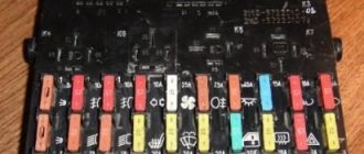
So, let's look at some of the above reasons in more detail. After the rheostat handle, you should check the integrity of the 5-amp fuse F1. You can also usually turn on the side lights and see if they work on the left side. Everything is explained here simply. The lamps that illuminate the instrument panel, the left side lights, as well as the trunk lighting operate through this fuse. The dimensions located on the right side of the car receive power through F11, that is, they are not of interest to us in this particular case.
You may see the following situation. The left side parking lights, or trunk light, work, but the instrument panel light does not. This means that the problem is not in fuse F1. Therefore, you need to continue searching for the possible cause of the malfunction. In particular, it is necessary to check the contacts of the rheostat that illuminates the dashboard lighting. It is not uncommon for plugs to fall off. Accordingly, the lighting of the shield disappears due to lack of contact.
However, the rheostat itself can also fail. It is quite easy to check this assumption. To do this, you must first remove the rheostat, and then directly connect its contacts. If after this manipulation the instrument panel lights come to life, it means that the problem has been found, and you just need to replace the failed part. If not, then you need to continue searching further.
The most serious problem due to which the instrument panel lighting disappears is damage to the printed circuit board of the dashboard itself. In particular, there are often situations when the track on it that supplies power to the lamps burns out. One point worth noting here. The instrument panel in such a situation cannot be repaired, which means there is only one way out - replacement with a new one.
There are cases when, due to a short circuit, all the lamps illuminating the instrument panel burn out. However, this happens quite rarely. Much more often, one lamp may fail. As you can see, there are several reasons why the instrument panel lighting may disappear. Accordingly, the search will take some time. However, in the vast majority of cases, eliminating the malfunction that has arisen will not be so difficult, and many people can easily do this with their own hands.
The VAZ 2112 instrument panel does not work - reasons
If the panel suddenly stops working:
- When the engine does not start and the dash does not work, inspect the ignition switch. Here the contact often burns out or oxidizes.
- If the machine is working and the panel has failed, you will need to check the corresponding fuse, wiring and lines.
- If the manipulations do not help, you will need to remove the device and test its circuits.
Panel backlight does not light up
There may be damage to the light activation key. It is recommended to check the corresponding fuse.
The panel is blinking
Consequence of deterioration of electrical wiring contacts. The user should inspect the supply wires for cracking or damaged insulation. The contact groups should be disconnected and cleaned of oxides and dirt. Treat the terminals with special oil.
Tidy 2112 stuck
This kind of problem is unexpected, but it occurs everywhere. As a repair, users are suggested to reset the electronic equipment. Remove the terminals from the battery and wait 15 minutes.
Connecting an alarm to the door limit switches of VAZ 2108, VAZ 2109, VAZ 21099, Lada Samara
In general, there are no special problems here.
The chisel uses a negative polarity circuit. That is, when the door is opened, the limit switch closes the white-black wire to ground, and the presence of ground on this wire serves as a signal for the door to open. Most VAZ 2108 alarms have such an input, usually designated as a “negative door trigger”. However, if you have a chisel with an injection engine and an APS-4 immobilizer, simply connecting the warhead wire to the alarm input is not enough. That is, it’s enough, but you will have to arm the car or after the “polite illumination” of the interior lamp goes out (if you don’t wait, the alarm will think that the doors are not closed, and at the moment of smooth extinguishing v it will think that the doors are being opened /close), or enable the “arming delay” function in the alarm system (if there is one). But in my opinion, both of these options are unacceptable. Counting to 20 every time is stupid, and leaving the car unguarded for 30..60 seconds is simply dangerous; during this time you will have time to lose a lot of things in the cabin.
The reason for the problem is that VAZ designers have included a delay function for turning off the interior lighting in the anti-theft system (a controversial step, of course, but the giraffe is big). It works as follows (see the top diagram in Fig. 1).
The green-black wire from the 10th contact of APS-4 is connected to the white-black wire of the door limit switches. This contact on APS-4 is both an input and an output. When the door opens, the limit switch closes the warhead wire to ground, and with it the AF wire of APS-4 and APS-4 “sees” that the door is open and goes into key reading mode. When the ignition is turned off and the door is closed (APS-4 “sees” this by the loss of ground on its AF wire), APS-4 itself “provides” mass to the AF and, therefore, to the warhead wire of the door limit switches. That’s why the lamp continues to light, and the alarm connected to the warhead wire “thinks” that one of the doors is open: there is a mass on the warhead wire, though not from the limit switch, but from the APS-4! But the most interesting thing begins with the “smooth extinguishing” of the interior light. For smooth extinction, APS-4 emits mass pulses with decreasing duty cycle to the lampshade. And the alarm thinks that the doors are opening and closing! True, some alarms “filter” such impulses and do not respond to these “openings”, and after a smooth extinguishing of the interior, they simply arm the doors.
The green-black wire from the 10th contact of APS-4 is connected by an insert between the warhead wire of the driver's door limit switch and the limit switch itself.
The problem can be solved in several ways: from barbaric cutting of the APS-4 to replacing the insertion of an additional end switch exclusively for the APS-4. In my opinion, the simplest and most correct way is to decouple the APS-4 and the warhead wire with a diode. To do this, you need to disconnect the “inset” of the AF wire between the AF wire and the driver’s limit switch. Connect the warhead wire directly to the limit switch. Everything here is on chips, there is no need to solder anything. Then you need to stretch the AF wire to the lampshade (it will have to be extended). It is better to pull it along the left pillar of the front door. It is not necessary to remove the ceiling if you have the skill. Otherwise, unscrew the fastenings of the sun visors and ceiling handle on the driver's side, and carefully bend the ceiling. Carefully! A delicate ceiling can be “broken” and then there will be an ugly stripe at the break point. From the lamp's connector, remove the chip to which two warhead wires go and insert the chip with the AF wire from the APS-4 there. Solder a diode between this wire and the warhead (which was removed from the connector), as shown in the bottom diagram of Fig. 1.
All. Now the alarm system, being connected to the warhead wire (in any place), will not respond to the “polite lighting”, and the alarm system will immediately protect the doors. Yes, and, of course, when the doors are opened, the APS-4 will go into key reading mode.
Description of the buttons on the panel
The situation is similar with the control keys for devices and machine components. Even an experienced driver can get lost here. The photo above shows the elements and switches installed in common versions.
| Number in photo | Purpose |
| 10 | Additional equipment control module. |
| 18 | Steering rack position regulator. |
| 19 | Hood lock drive. |
| 20 | Horn button. |
| 22 | Trunk lock actuator button. |
| 24 | Hydrocorrector of headlights. |
| 25 | Switch for turning mode and headlights. |
| 26 | External lighting switch button. |
| 27/31 | Front/rear fog light switch. |
| 33 | Button for turning on the rear window heater. |
| 34 | Instrument lighting regulator. |
| 38 | Exhaust gas recirculation switch. |
| 39 | Air conditioner control buttons. |
| 40 | Heater damper position regulator. |
| 42 | Emergency button. |
| 43 | Switch for wipers and headlight washers. |
Europanel
Note Some versions of cars of later releases (in particular, models produced) are equipped with a modified instrument panel - the so-called “European panel”.
- Left side deflector.
- Outdoor lighting buttons.
- Instrument cluster.
- Egnition lock.
- Right steering column switch (windshield wipers and washers).
- Hazard warning light button.
- Instrument lighting control knob.
- Immobilizer sensor with indicator.
- Rear window heating switch.
- Plugs (reserve places for installing switches for additional equipment).
- Central deflectors.
- Heater control panel.
- Covers for niches for installing car radios.
- Right side deflector.
- Left steering column switch (direction indicators and headlights).
- Hood release lever.
- Steering wheel.
- Clutch pedal.
- Brake pedal.
- Accelerator pedal.
- Socket for connecting a portable lamp.
- Gear shift lever.
- Ashtray cover.
- Cigarette lighter.
- Glove box.
- Parking brake lever.
Features of connecting BC
In conclusion, I would like to dwell in more detail on such a point as installing an on-board computer. In the typical pinout diagram shown just above, there is only one wire leading to it - brown. But for the correct operation of this device, this alone will not be enough. Therefore, here is a complete pinout diagram for connecting the on-board computer:
- Green wire – comes from the electronic control unit, needed to obtain information about fuel consumption.
- Orange – goes to the ignition switch, to terminal 15.
- White-red - in the same place, only to terminal 30.
- The common ground wire is black.
- Brown – needed to take speed data.
- Red-green - to the positive circuit of the fuel level sensor.
- White - leads to the light control, which is responsible for the lamps that illuminate the instrument panel.
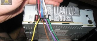
Hello everyone) A new entry is dedicated to the transition from the AutoDevice (AP) panel with one window 2110-3801010-04 to the new VDO Panel 1118-3801010. The devices are completely different, so the modifications affected primarily the pads.
I took a new 32-pin block from the VAZ 2112 harness; I haven’t seen it on sale separately yet.
It’s not possible to get the contacts out of the green block, unlike the old 13-pin ones. Therefore, the wires were cut with a margin. Then they were soldered to the ends of the wires from the white and red blocks, and covered with heat shrink for insulation.
Information that was used during electrical work: Pinout of old-style VAZ 2110 instrument cluster connectors:
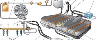
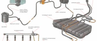
Wiring diagram for fog lights.
According to the factory connection diagram, the fog lights turn on after the headlights are turned on. In this case, you can leave the headlights on with the engine off, which will drain the battery. To prevent this situation, it is better to connect the relay control wire to the terminal from the ignition switch (red in the diagram). But if you want to leave the switch on together with the dimensions, then pin 30 of the relay is best connected to a wire receiving power through the ignition switch. It should be taken into account that the load on the ignition switch will increase.
Installation and repair instructions
Replacing the panel, especially if you are installing it on an old VAZ 2112, is a certain difficulty. Older machines do not have some of the functions for which the panel has buttons. The wiring may need to be worked on.
Tools and materials
Standard tools will be required.
But a certain amount of additional materials is needed:
- you will need plugs for extra buttons that are not needed on an old car;
- air duct;
- various inserts, buttons (5 pieces) and pads;
- a new wiring harness suitable for the wiring diagram;
- brackets for mounting the instrument panel;
Algorithm of actions
First you need to remove the old panel. This is done in the same way as on other models of VAZ cars.
When installing, you need to replace the ignition switch with a decimal or Kalinovsky one, depending on how many terminals there are on the block to the lock. You can leave the old one and rearrange the wires, but the new one will work and look better.
The instrument panel wiring needs to be replaced. Also, connect the dimensions with additional two wires in Ш4/13 and Ш3/13 on the mounting block. This applies to older units with 11 relay spaces.
Depending on whether it is an injector or a carburetor, the connection has its own nuances. If you bought a solid factory panel, then instructions should be included with it. Briefly, it can be noted that the injector is not equipped with a speed sensor, please take this into account when installing.
The car's electrical circuit can be of great help. If it is not there, you can find it on the Internet. There are some differences between the VAZ 21124, 2111 and other car variants, so find yours.
If the instrument panel does not work after turning it on, check that the wiring is connected correctly - this is usually the error.
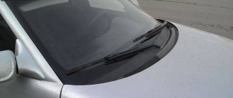
Illumination of buttons on the VAZ 2110 panel
Now it all depends on your imagination and means. For example, you can buy a ready-made LED lamp of any color. I used my own design (my first experience in soldering SMD components =)). In the case of LEDs, please note that “+” is contact No. 6, and “-” is contact No. 7 (we look at the back of the case where the block with wires is inserted).
Now we need to get rid of the standard green plastic filter with the fog light icon. At first I tried to use a soldering iron, but later abandoned this idea. The most reasonable thing, in my opinion, is to drill it out, with a very thin drill of about 1mm. The holes must be made carefully so that the drill does not pierce through the entire structure. To determine the thickness, I drilled the first hole in thin layers until I saw white plastic. As a result, having removed the light filter from the structure, we will assemble it and check its functionality.
Well, that's it! =)
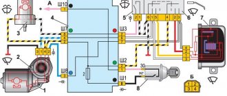
The electrical circuit of the VAZ-2110 is single-wire, that is, only one wire passes from the power source to the consumer, through which the plus is supplied. The downside to this combination is the weight of the car. Most circuits are energized when the ignition is turned on. This is done to reduce the load on the battery when the engine is not running and prevent its discharge.
Under constant power, regardless of whether the ignition is turned on, there are circuits for the sound signal, brake light, courtesy light and others whose operation must be independent of engine operation. The electrical circuit of the VAZ-2110 is identical to the electrical circuit of the VAZ-2111 (2112; 2114).
The circuit consists of four bundles, which are divided depending on their location. In particular, in the engine compartment there are two harnesses, one of which runs along the left wing, and the second connects the ignition system in carburetor cars or sensors and actuators with the controller, with the injection engine. There are also two harnesses in the cabin, one of which connects to the consumers on the left side, instruments, controls, and so on, and the harness that supplies the interior lighting and consumers located in the rear of the car. The harnesses are connected to each other through a mounting block, which acts as a switching device, and a plug connector located under the panel.
Ignition and engine control circuit
Here are the control diagrams for the following internal combustion engines:
- 21120 – January 5.1 or BOSCH M1.5.4N, Euro-2;
21120 (Euro-2) 21124 (Euro-2) 21124 (Euro-3)
| Motor | 21120 (Euro-2) | 21124 (Euro-2) | 21124 (Euro-3) |
| Injectors | 1 | 2 | 2 |
| Ignition coil | – | 1 | 1 |
| Candles | 2 | – | – |
| Ignition module | 3 | – | – |
| Diagnostic connector | 4 | B | B |
| ECU | 5 | 3 | 3 |
| Tidy taps | 6 | E | E |
| Ignition relay (6) | 7 | 4 | 4 |
| Ignition fuse (1) | 8 | 5 | 5 |
| Fan relay (4) | 9 | 6 | 6 |
| Fan fuse (2) | 10 | 7 | 7 |
| Fuel pump relay (5) | 11 | 8 | 8 |
| Fuel pump fuse (3) | 12 | 9 | 9 |
| Mass air flow sensor | 13 | 10 | 10 |
| Rough road sensor | – | – | 11 |
| TPDZ | 14 | 11 | 12 |
| DTOZH | 15 | 12 | 13 |
| RXX | 16 | 17 | 14 |
| Lambda probe main | 17 | 14 | 15 |
| Additional lambda probe | – | – | 16 |
| Knock sensor | 18 | 15 | 18 |
| DPKV | 19 | 16 | 19 |
| Canister purge valve | 20 | 13 | 17 |
| APS block | 21 | 18 | 20 |
| APS indicator | 22 | 19 | 21 |
| Speed sensor | 23 | 21 | 23 |
| Fuel pump + level sensor | 24 | 22 | 24 |
| Oil pressure sensor | 25 | 23 | 25 |
| Antifreeze thermometer sensor | 26 | 24 | 26 |
| Oil level sensor | 27 | – | – |
| Phase sensor | 28 | 20 | 22 |
| ABS connector | A | A | A |
| Air conditioner connector | B | IN | IN |
| Fan connector | C | – | – |
| Illumination of the ignition switch (to the blue-white wire) | D+E | – | – |
| Bends to the door harness | – | D | D |
| + battery | F | G | G |
| Weight | G1+G2 | G1+G2 | G1+G2 |
Europanel "LUX" (instrument panel) assembled VAZ 2110-12
Installed on VAZ 2110, 2111, 2112 cars. This panel has been installed from the factory on these cars in the “Lux” configuration since 2006.
It is installed in standard places, without any modifications, since the kit includes everything necessary for its installation.
This product is not sent by Russian Post, EMS courier or 1CLASS due to its size and fragility. Only by transport companies.
Attention! Europanel is sent only by a transport company due to its size! If you have doubts about the availability of a transport company in your city, leave this question to us, we will select the optimal company for you.
Encyclopedia of tuning and modifications for VAZ 2110, VAZ 2112
| When using additional accessories (navigator, video recorder, radar detector, etc.) in the car interior, it may be necessary to install additional buttons. Do you know what to do if there is no free space for them on the panel? |
| Some versions of VAZ vehicles are equipped with an electric trunk lock. During operation, many encounter a problem when the trunk release button does not work. Let's consider the possible causes of this malfunction. |
How to install the trim without disassembling the dashboard
Any dashboard on a VAZ 2110 consists of several parts, but the Euro panel is only a cover on the top of the dashboard. And just so as not to completely disassemble the instrument panel, you can replace only its upper part.
Replacement is carried out as follows:
- Remove the instrument panel.
- Open the glove compartment, unscrew several screws inside it.
- Next, you need to pull out the ECU and unscrew the screws behind it.
- Loosen the fuse panel.
- Then you need to unscrew the screws that hold the panel on top. And after that you can remove the old trim.
Device
In this case, the instrument cluster on the VAZ 2110 includes:
- Tachometer;
- speedometer;
- Fuel level indicator;
- Coolant temperature gauge;
- Indicator lamps in the amount of 12 pieces;
- 6 instrument panel suspension lights;
- Reserve socket for control lamp;
- A pair of terminals for connecting wires.
Tidy pinout
As for the instrument panel, two types are used for the VAZ 2110 model. It all depends on the year of the car as there is an old version and an updated version.
Before you begin to solve the problem yourself, we recommend that you familiarize yourself with the pinout of the instrument panel on the VAZ 2110. In other words, you should understand where which wiring leads, what it is intended for, what fuses are available, and so on.
Cigarette lighter failure
It is its malfunction that often causes the shield to fail. The fact is that many car owners turn on various devices through the cigarette lighter, for example, a special vacuum cleaner, chargers, pumps and other devices. Due to the fact that these gadgets require high current, either the socket itself or fuse F19 often breaks, as a result of which the instrument panel on the VAZ-2110 does not work.
In addition, the cigarette lighter may become damaged if left on for too long. In this case, you can return the instrument panel to functionality by disconnecting the socket block. But it is worth saying that such manipulation will be successful only if fuse F19 is functioning. If it does burn out, it must be replaced.
This is interesting: Why on the VAZ-2110 the stove does not work and does not blow
Problems and their solutions
Old and new sample
There are several common problems typical for the dashboard of the domestically produced VAZ 2110 model.
As practice shows, most problems associated with the failure of the dashboard can be solved independently. Especially when it comes to a car like the VAZ 2110.
Possible faults
The panel is being installed on a VAZ 2114.
Possible problems with the panel may be due to incorrect connection. Because of this, some or even all of the indicators may not work.
If initially everything functioned normally, and then some malfunctions arose, check the condition of the wiring. After prolonged use, various buttons may fall off, but they can be easily replaced. The fuse block also burns out; replacing it will cost 1,800 rubles.
see also
Comments 29
I'll tell you which ones later
I connected the wires and they also get hot
Hello I have a VAZ 2112, I want to change the instrument panel From Priora I can’t find the exact connection diagram Please send the diagram Thank you in advance
It’s easier to take it to an electrician)) and it’s a molorik))!
I connected everything according to your diagram. But my front PTFs don’t work. I don’t know why. And when I rearranged the main wires (Fig. 1), I was left with green wire 56. It went along the old block to the front PTF. But on the new PTF button there is no longer room for this wire. Where did you connect it?
Having connected according to your diagram (low and side) I got this - when you turn on the side, the ignition and side turn on, there is no front... maybe I mixed something up... I can’t figure it out ((((
Look at contacts 58,X X-ignition is on 58-gabor 30-constant plus When the button is turned on, the ignition goes from 30 to 58 and the side light is ON When power comes to X, you can turn on the low beam and the power goes to 56, the low beam turns on
Having connected according to your diagram (low and side) I got this - when you turn on the side, the ignition and side turn on, there is no front... maybe I mixed something up... I can’t figure it out ((((
the problem was in contacts 5 and 6, I swapped them and everything worked
very useful information, I will try your scheme and connect over the weekend)
Guys, thank you very much for the information, the diagrams really saved me! I'm replacing the 2112 panel with a Euro one, using viburnum as the donor. The tidy is already connected, button crap with 10 is difficult to redo without pads
The circuits are real, I developed them myself for two weeks, by mistake and error, everything was connected in my previous car, everything worked like stock.
And were the button lighting illuminated when the dimensions and low/high beams were on?
Yeees! The backlight did not turn off after turning on the dimensions until the dimensions were turned off =)
Do your double button lights come on after ignition?
no, when you press the taillights button, all the interior lights and the parking lights in the front and rear come on.
Well, there’s a feature of these buttons - you turn on the ignition and the button icons of the double button are highlighted, that’s what pin 4 is there for
Components
When purchasing, you will receive what is included in the kit, namely:
- Europlate;
- Inserts for switches (buttons) of devices;
- Trim on the instrument panel;
- Since your instrument combination may differ from those whose installation is structurally provided, there should also be six plugs; they can be inserted instead of buttons;
- The buttons themselves and two pads for them: • Double – for low beam and dimensions; • To turn on the fog lights; • Heated rear window.
- Air ducts;
- Block and wiring harness designed to connect a double button for side lights and low beam;
- Brackets securing the instrument panel.
In addition, if you are not entirely satisfied with this combination, and you need more buttons for other devices, then they, as well as the pads for them, can be purchased separately.
Source
Low beam button illumination VAZ 2110 (European panel)
Method No. 1
We remove the two buttons (turn on the side lights and low beam headlights), and carefully disassemble them. Illumination of the low beam button is not provided by the manufacturer, so to install a light filter in the button, you will first need to cut out the plug.
Then we lay two wires through the button, which we solder to a pre-installed LED. Don't forget about the resistance for the LED, which is more convenient to place behind the button.
Connecting the button backlight:
- We hook the mass onto the body.
- We connect the “plus” to the mounting block, contact Ш3-1 or Ш3-3 (the plus appears here after the ignition is turned on).
All that remains is to assemble the button in the reverse order and check the operation of the indication.
Method No. 2
We make the contacts into the plug from a female connector, onto which we extend the wires. Then remove the top light bulb with copper contacts on the back side:
- Ignition is on.
- Dimensions included.
- Low beam is on.
By the way, on the old-style dashboard there are button indicators, but they are blocked by the steering wheel rim, so duplicate LEDs are installed.