The power supply system is part of the electronic engine management system, which is described in detail in a separate “Repair and Maintenance Manual for the Engine Management System with Multiport Fuel Injection.”
FUEL SUPPLY SYSTEM
The function of the fuel supply system is to ensure that the required amount of fuel is supplied to the engine at all operating conditions. Fuel is supplied to the engine by injectors installed in the intake pipe.
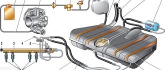
Rice. 2-62. Fuel supply system with distributed injection: 1 —
fitting for monitoring fuel pressure; 2 — injector ramp; 3 — fuel pressure regulator; 4 — electric fuel pump; 5 - fuel filter; 6 — fuel drain line; 7 — fuel supply line; 8 — nozzles
The fuel supply system (Fig. 2-62) includes: electric fuel pump 4, fuel filter 5, fuel lines (supply 7 and drain 6), injector ramp 2 with fuel injectors 8, fuel pressure regulator 3 and fuel pressure control fitting 1.
An electric fuel pump installed in the fuel tank supplies fuel through the main fuel filter and the fuel supply line to the injector rail.
The fuel pressure regulator maintains a constant pressure difference between the inlet pipe and the injection rail. The fuel pressure supplied to the injectors is within 300+6 kPa when the engine is not running. Excess fuel beyond that required by the injectors is returned to the fuel tank through a separate drain line.
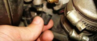
Before servicing fuel equipment, it is necessary to relieve the pressure in the fuel supply system.
When disconnecting fuel lines, do not allow fuel to spill. To do this, wrap the ends of the tubes with a rag.
The procedure for relieving pressure in the fuel supply system:
1. Engage neutral gear and brake the vehicle with the parking brake.
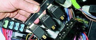
2. Disconnect the wires from the electric fuel pump (see Fig. 2-63), to do this, tilt the rear seat cushion forward and remove the electric fuel pump flap.
3. Start the engine and let it idle until it stops due to fuel exhaustion.
4. Turn on the starter for 3 seconds to relieve pressure in the pipelines. After this, you can safely work on the fuel supply system.
5. After releasing the pressure and completing the work, connect the wires to the electric fuel pump.
Rice. 2-63. Location of the electric fuel pump
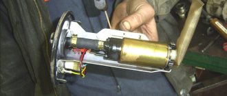
Electric fuel pump. The system uses a turbine-type electric fuel pump. The pump supplies fuel from the fuel tank through the main fuel filter to the injector rail. Excess fuel is returned to the gas tank through a separate drain line.
The electric fuel pump is switched on by the controller via a relay. When the ignition key is set to the IGNITION or STARTER position after being in the OFF position for more than 15 seconds, the controller energizes the relay for 3 seconds to create the required fuel pressure in the injector rail.
If the engine does not start cranking during this time, the controller turns off the relay and waits for cranking to begin. After it starts, the controller turns on the relay again.
Fuel filter 1 (Fig. 2-64) is installed under the underbody near the fuel tank 2. The filter is built into the supply line between the electric fuel pump and the fuel rail.
The filter has a steel body with threaded fittings at both ends. The filter element is made of paper and is designed to trap particles that could cause problems with the injection system.
Rice. 2-64. Fuel filter location: 1 - fuel filter; 2 - fuel tank
Removing the fuel filter:
1. Relieve pressure in the fuel supply system (see above).
2. Unscrew the nuts securing the fuel pipes to the filter. Avoid losing the O-rings installed between the filter and the tube tips.
ATTENTION. Be sure to use a second wrench on the fuel filter side when loosening the fastening nuts.
3. Remove the filter mounting clamp.
Installing the fuel filter
Check the O-rings for cuts, nicks or abrasions. Replace rings if necessary.
1. Install the filter so that the arrow on its body corresponds to the direction of fuel supply, and secure the filter with a clamp.
2. Attach the fuel pipes to the filter, tightening the fastening nuts to a torque of 20-34 Nm.
ATTENTION. Be sure to use a second wrench on the fuel filter side when tightening the fastening nuts.
3. By applying +12 V voltage to the pGc contact of the diagnostic block, turn on the electric fuel pump and make sure there are no fuel leaks.
Removing the injector ramp
When removing the ramp, be careful not to damage the connector contacts and injector nozzles.
Keep dirt and foreign materials away from open pipes and ducts. During maintenance, close the fittings and openings with plugs.
Before removal, the injector rail can be cleaned with a spray of engine cleaner. Do not dip the ramp into cleaning solvent.
1. Relieve pressure in the fuel supply system.
2. Turn off the ignition.
3. Disconnect the wire from the negative terminal of the battery.
4. Disconnect the throttle valve drive from the throttle pipe and the receiver.
5. Disconnect the inlet pipe hose from the throttle pipe.
6. Unscrew the nuts securing the throttle pipe to the receiver and, without disconnecting the hoses with coolant, remove the throttle pipe from the receiver.
7. Remove the fuel supply and drain pipes, disconnecting them from the injector ramp, pressure regulator and from the bracket on the cylinder head.
ATTENTION. Be sure to use a second wrench on the side of the fuel supply fitting of the fuel rail when unscrewing the union nut of the fuel pipe.
8. Disconnect the vacuum hose from the pressure regulator.
9. Unscrew the nuts securing the receiver and remove it from the inlet pipe.
10. Remove the injector wiring harness by disconnecting it from the injection system and injector harness.
11. Unscrew the bolts securing the injector ramp and remove it.
ATTENTION. If the injector has separated from the rail and remains in the intake pipe, both O-rings and the injector retainer must be replaced.
Installing the injector ramp:
1. Replace and lubricate the new injector sealing rings with engine oil, install the fuel rail assembly on the cylinder head and secure with bolts, tightening them to a torque of 9-13 Nm.
Supply system
The power supply system is part of the electronic engine management system, which is described in detail in a separate “Repair and Maintenance Manual for the Engine Management System with Multiport Fuel Injection.”
FUEL SUPPLY SYSTEM
The function of the fuel supply system is to ensure that the required amount of fuel is supplied to the engine at all operating conditions. Fuel is supplied to the engine by injectors installed in the intake pipe.
Rice. 2-62. Fuel supply system with distributed injection: 1 —
fitting for monitoring fuel pressure; 2 — injector ramp; 3 — fuel pressure regulator; 4 — electric fuel pump; 5 - fuel filter; 6 — fuel drain line; 7 — fuel supply line; 8 — nozzles
The fuel supply system (Fig. 2-62) includes: electric fuel pump 4, fuel filter 5, fuel lines (supply 7 and drain 6), injector ramp 2 with fuel injectors 8, fuel pressure regulator 3 and fuel pressure control fitting 1.
An electric fuel pump installed in the fuel tank supplies fuel through the main fuel filter and the fuel supply line to the injector rail.
The fuel pressure regulator maintains a constant pressure difference between the inlet pipe and the injection rail. The fuel pressure supplied to the injectors is within 300+6 kPa when the engine is not running. Excess fuel beyond that required by the injectors is returned to the fuel tank through a separate drain line.
Before servicing fuel equipment, it is necessary to relieve the pressure in the fuel supply system.
When disconnecting fuel lines, do not allow fuel to spill. To do this, wrap the ends of the tubes with a rag.
The procedure for relieving pressure in the fuel supply system:
1. Engage neutral gear and brake the vehicle with the parking brake.
2. Disconnect the wires from the electric fuel pump (see Fig. 2-63), to do this, tilt the rear seat cushion forward and remove the electric fuel pump flap.
3. Start the engine and let it idle until it stops due to fuel exhaustion.
4. Turn on the starter for 3 seconds to relieve pressure in the pipelines. After this, you can safely work on the fuel supply system.
5. After releasing the pressure and completing the work, connect the wires to the electric fuel pump.
Rice. 2-63. Location of the electric fuel pump
Electric fuel pump. The system uses a turbine-type electric fuel pump. The pump supplies fuel from the fuel tank through the main fuel filter to the injector rail. Excess fuel is returned to the gas tank through a separate drain line.
The electric fuel pump is switched on by the controller via a relay. When the ignition key is set to the IGNITION or STARTER position after being in the OFF position for more than 15 seconds, the controller energizes the relay for 3 seconds to create the required fuel pressure in the injector rail.
If the engine does not start cranking during this time, the controller turns off the relay and waits for cranking to begin. After it starts, the controller turns on the relay again.
Fuel filter 1 (Fig. 2-64) is installed under the underbody near the fuel tank 2. The filter is built into the supply line between the electric fuel pump and the fuel rail.
The filter has a steel body with threaded fittings at both ends. The filter element is made of paper and is designed to trap particles that could cause problems with the injection system.
Rice. 2-64. Fuel filter location: 1 - fuel filter; 2 - fuel tank
Removing the fuel filter:
1. Relieve pressure in the fuel supply system (see above).
2. Unscrew the nuts securing the fuel pipes to the filter. Avoid losing the O-rings installed between the filter and the tube tips.
ATTENTION. Be sure to use a second wrench on the fuel filter side when loosening the fastening nuts.
3. Remove the filter mounting clamp.
Installing the fuel filter
Check the O-rings for cuts, nicks or abrasions. Replace rings if necessary.
1. Install the filter so that the arrow on its body corresponds to the direction of fuel supply, and secure the filter with a clamp.
2. Attach the fuel pipes to the filter, tightening the fastening nuts to a torque of 20-34 Nm.
ATTENTION. Be sure to use a second wrench on the fuel filter side when tightening the fastening nuts.
3. By applying +12 V voltage to the pGc contact of the diagnostic block, turn on the electric fuel pump and make sure there are no fuel leaks.
Removing the injector ramp
When removing the ramp, be careful not to damage the connector contacts and injector nozzles.
Keep dirt and foreign materials away from open pipes and ducts. During maintenance, close the fittings and openings with plugs.
Before removal, the injector rail can be cleaned with a spray of engine cleaner. Do not dip the ramp into cleaning solvent.
1. Relieve pressure in the fuel supply system.
2. Turn off the ignition.
3. Disconnect the wire from the negative terminal of the battery.
4. Disconnect the throttle valve drive from the throttle pipe and the receiver.
5. Disconnect the inlet pipe hose from the throttle pipe.
6. Unscrew the nuts securing the throttle pipe to the receiver and, without disconnecting the hoses with coolant, remove the throttle pipe from the receiver.
7. Remove the fuel supply and drain pipes, disconnecting them from the injector ramp, pressure regulator and from the bracket on the cylinder head.
ATTENTION. Be sure to use a second wrench on the side of the fuel supply fitting of the fuel rail when unscrewing the union nut of the fuel pipe.
8. Disconnect the vacuum hose from the pressure regulator.
9. Unscrew the nuts securing the receiver and remove it from the inlet pipe.
10. Remove the injector wiring harness by disconnecting it from the injection system and injector harness.
11. Unscrew the bolts securing the injector ramp and remove it.
ATTENTION. If the injector has separated from the rail and remains in the intake pipe, both O-rings and the injector retainer must be replaced.
Installing the injector ramp:
1. Replace and lubricate the new injector sealing rings with engine oil, install the fuel rail assembly on the cylinder head and secure with bolts, tightening them to a torque of 9-13 Nm.
2. Connect the injector wiring harness.
3. Install the receiver.
4. Install the fuel pipes by tightening the union nuts attaching to the ramp and pressure regulator to a torque of 20-34 Nm.
ATTENTION. Check fuel pipe O-rings for cuts, nicks or abrasions. Replace if necessary.
Be sure to use a second wrench on the side of the ramp fitting when tightening the fuel pipe tension nut.
5. Install the pressure regulator vacuum hose.
6. Install the throttle pipe on the receiver and secure it with nuts.
7. Connect the intake pipe hose to the throttle pipe.
8. Install the throttle valve actuator and check its operation.
9. Connect the wire to the negative terminal of the battery.
10. By applying +12 V voltage to the pGc contact of the diagnostic block, turn on the electric fuel pump and make sure there are no fuel leaks.
The injector (Fig. 2-65) of the distributed injection system is an electromagnetic device that meteres the supply of fuel under pressure into the engine intake pipe.
Fuel supply system VAZ 2115
The function of the fuel supply system is to ensure that the required amount of fuel is supplied to the engine at all operating conditions. Fuel is supplied to the engine by injectors installed in the intake pipe.
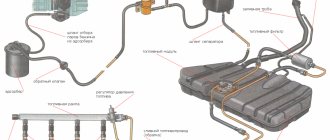
Rice. 2.80. Fuel supply system with distributed injection: 1 – fitting for monitoring fuel pressure; 2 – injector ramp; 3 – bracket; 4 – fuel pressure regulator; 5 – electric fuel pump; 6 – fuel filter; 7 – fuel drain line; 8 – fuel supply line; 9 – nozzles
The fuel supply system (Fig. 2.80) includes: electric fuel pump 5, fuel filter 6, fuel lines (supply 8 and drain 7), injector ramp 2 with fuel injectors 9, fuel pressure regulator 4 and fuel pressure control fitting 1.
An electric fuel pump installed in the fuel tank supplies fuel through the main fuel filter and the fuel supply line to the injector rail.
The fuel pressure regulator maintains a constant pressure difference between the inlet pipe and the injection rail. The fuel pressure supplied to the injectors is within 300±6 kPa when the engine is not running. Excess fuel beyond that required by the injectors is returned to the fuel tank through a separate drain line.
Before servicing fuel equipment, it is necessary to relieve the pressure in the fuel supply system.
When disconnecting fuel lines, do not allow fuel to spill. To do this, wrap the ends of the tubes with rags.
Video about “Fuel supply system” for VAZ 2115
Engine fuel system Low fuel pressure, what is the problem Injector!? VAZ
The smell of gasoline, replacing the separator and gas tank valves of VAZ 2108, 2109, 21099, 2113, 2114, 2115
Source
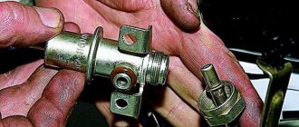
Why is this device needed?
The regulator, responsible for maintaining normal fuel pressure in the system, is in direct interaction with the power unit. According to its location, it can be located in the fuel tank or in the rail (this is where you will be able to find the regulator if you have an injection VAZ-2115). The reason for the failure of this element is often the low quality of gasoline. If you fill up at gas stations with greatly reduced prices, then it is not surprising that very soon the regulator will fail.
The fuel flows through the injectors to the intake manifold, and it is important that its pressure does not change at this moment. The regulator measures the volume of fuel required for engine operation, and also monitors the pressure in the fuel rail and intake manifold.
The main task of the RTD is to maintain the pressure difference at the same level, as well as monitor the indicators.
The principle of operation of the main elements of the fuel unit
Fuel system VAZ 2114
Container for storing flammable materials
It is made of steel, consists of two firmly welded parts, the neck through which the fuel enters is connected to the tank with a rubber pipe and secured with clamps.
Gasoline pump
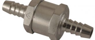
This tool with an electric mechanism is located in a tank with a fuel mixture level indicator. Its actions are coordinated by the engine control box, through a special pump relay, which supplies fuel through the line to the injectors. At idle or when the engine is completely turned off, the pressure is maintained due to the action of a one-way lock, which is located near the unit itself.
The VAZ 2114 power system has a fuel pressure regulator and injectors. The voltage is supplied to them from the battery through the main relay. Thus, the amount of driving fluid is indicated by the duration of the pulses, which are generated by the engine control unit and transmitted to the injectors.
Ramp
Located on the intake manifold, it includes a fuel control element and a pressure valve with a spring-loaded diaphragm. It, in turn, divides the regulator body into 2 parts: the fuel part regulates the pressure of the combustible mixture, the air part, due to the rarefaction of the air, raises the membrane and produces constant fuel pressure readings in the rail.
When the engine starts, the vacuum behind the damper decreases, the diaphragm closes the power system valve, so the pressure increases. When the vacuum is maximum, then the fuel pressure decreases. The regulator is not dismountable, so if it fails, it is replaced with another one.
Fuel mixture control sensor
The pump module has a float, which is located in the tank cavity. When the position of the float changes, the resistance of the unit changes proportionally. According to a certain signal, the fuel quantity indicator on the dashboard displays the presence of fuel in the system.
Why does the sensor often fail?
- fragility of the case;
- frequent temperature changes;
- condensation formation in the tank;
- when using a low-quality combustible mixture;
- oxidation of contacts when sealing is broken.
That is why it is so important to carry out preventive maintenance on time, clean the unit, change contacts in order to prevent its destruction. Changing a device is not that easy. Many markings are original and unique, which means that the services of professionals will be required, which are also not cheap.
Hoses and pipelines
Such irreplaceable products guarantee uninterrupted circulation of flammable liquid from the container to the main line and nozzles, and if there is excess, they transfer the residual liquid back to the tank. The pipelines are located on the bottom of the vehicle, they need to be carefully checked, cleaned, inspected for integrity, various deformations identified and promptly eliminated in order to avoid fuel leakage, as well as poor transmission to the injectors.
Another function of the pipelines is the transfer of fuel vapor from the tank to the activated carbon section, where waste is collected when the engine is turned off. After it is started, the electromagnetic device is triggered and the vapors escape into the engine, where they are destroyed.
Highway
The design of the VAZ 2114 fuel system includes a main line that guarantees the supply of fuel to all injectors. Today, the fuel pressure regulator is placed in the tank and is not located on the line; there is also a service valve, which performs the function of eliminating air after a technical inspection of the vehicle.
The fuel injection system of the VAZ 2114 includes an uninterrupted mode for collecting fuel vapors, and the gravitational unit located in the device helps prevent fuel from leaking when the vehicle is in an emergency position.
When the engine's air consumption is high, the system is purged more intensively. The filter element is made of durable paper material, after which the air moves through the mass air flow sensor and moves into the intake hose, which leads to the throttle assembly. Thus, the operation of the fuel fluid supply mode of an engine with a fuel injection system on a VAZ 2114 car occurs.
A whole complex of devices combined into one fuel system is responsible for supplying fuel to the VAZ 2114 engine. This article is dedicated to it, by studying which you will learn what the power supply system of the VAZ 2114 injector consists of, what is the principle of its operation, and what preventive measures must be taken in order for the system to work out its resource to the fullest.
The fuel supply system is the main artery of the car
Main symptoms of a malfunction
Problems with the regulator can manifest themselves in various ways:
- reduction in engine power (you can notice this when driving downhill or during acceleration);
- problems with starting the power plant (the starter rotates, but the engine does not start);
- Unstable engine operation at idle (you may often stall at intersections).
Even an inexperienced car user can notice these failures. It is important to diagnose your car in a timely manner so as not to spend money on fixing more serious breakdowns later. If you detect these signs in time, you will be able to carry out the repair yourself. Otherwise, you will have to evacuate the car to a service station.
Problems and repairs
Very often, Solex carburetors encounter a problem such as clogging of the inlet hole in the first chamber. This is due to the fact that after long-term operation of the engine, carbon particles appear on the cylinder walls, which enter the chamber along with the air entering the carburetor. Repairing this problem is quite simple. In order to clean the holes and chambers from carbon deposits, use a special liquid that is sold in every Automotive store. It eats away carbon particles and cleans the carburetor. If such a breakdown caught you on the road, and you did not have a cylinder with such a liquid at hand, then the following scheme of actions will help you:
- Without turning on the ignition, pull the choke lever towards you until it stops;
- Start the engine;
- Gradually and smoothly release the choke, and when you feel that the car is about to stall, press the gas pedal all the way. You need to provoke the opening of the second chamber, and then the carbon particles will fly out of the hole under high pressure.
Remember that this method will relieve you of the problem for a while. To completely solve it, contact a service station, where the carburetor will be repaired.
Another weak point of Solex carburetors is the small hole in the idle jet. This is fraught with the fact that even a small speck can clog the hole, and the car will stall at idle. In such a situation, no repair is required. Simply remove the jet and blow it out thoroughly.
The third problem, which very often occurs on carburetors of VAZ 2108 cars, is wear of the economizer gasket. At the same time, the engine's idle speed will not be stable, and the exhaust gases will turn black. Repair is carried out by replacing the gasket.
There are rarely cases when the amount of carbon deposits entering the chamber is very large. This mainly happens to those cars that have not undergone major repairs in a timely manner. Since the previously described scheme will not help you get to the nearest service station, you need to act more radically. Experts, in this case, recommend disconnecting the breather from the carburetor, directing its flow downward, using a long hose. This will help you somehow get to the station where repairs can be carried out.
Remember to periodically clean the Breather
Don't forget that the carburetor must be adjusted correctly. The VAZ 2108 carburetor is adjusted as follows: tighten the quality screw and the quantity screw until it stops, turning them clockwise with a screwdriver. Next, unscrew the quantity screw by one and a half turns, and the quality screw by 3.5. This is a mixture adjustment with minimal spark plug wear. If the spark plugs are worn out enough, add 1 - 1.5 turns for quality. With normal settings, the Solex should provide the engine with 800 - 900 rpm at idle. Under such conditions, repairs will very rarely be necessary.
When can fuel consumption increase?
It is worth paying special attention to such a sign of a regulator malfunction as increased fuel consumption.
The car will require more gasoline to operate if the valve in the regulator is faulty or, conversely, it does not hold fuel. In the first case, excess fuel is not returned to the tank; the car owner may notice a pressure above 2.5 kg/cm2. As a result, more gasoline enters the combustion chamber of the engine, which is not completely consumed. If the valve does not perform its functions, fuel “staggers” through the system. The pressure in the fuel system decreases, and as the speed increases, the engine feels a clear shortage of gasoline. The power unit becomes less responsive and powerful. A valve malfunction can be noticed when starting the car for a long time - during the process, the starter has to be turned for a long time until it creates the necessary pressure.
Removing, installing and replacing the fuel pump
If the VAZ fuel pump does not work, the car's fuel system needs to be repaired. Before you begin repairs, you will need to disconnect the negative terminal on the car battery. In addition, work must be carried out with the car’s gas tank empty. Replacing the fuel pump is carried out by dismantling the fuel module, which makes it possible to clean the bottom of the gas tank from accumulated sediment.
In order to replace a failed device, you will need to relieve the fuel pressure inside the fuel line. This is done by unscrewing the fuel rail fitting plug using a thin screwdriver. To remove the fuel module, you will need to prepare some tools:
- figured and flat screwdrivers;
- key number 17;
- head number 7;
- rags.
If the VAZ 2114 fuel pump does not work, then to replace it you need to perform a certain sequence of operations. First, two self-tapping screws are unscrewed, which secure the cover that closes free access to the installation site of the vehicle’s fuel module. After removing the cover, the electrical connector is disconnected from the assembly.
A number 17 wrench is then used to unscrew the fuel lines, being careful not to lose the special O-rings that ensure a tight connection. After disconnecting the pipelines, they are carefully moved to the side of the fuel module, allowing full access to it.
Using head number 7, unscrew the nuts that secure the pressure plate. It ensures the retention of the entire fuel module. After removing the plate, the module is removed from the tank cavity; to do this, you first need to release the fuel level sensor float.
If the module is assembled, it is installed in place of the removed one. However, if it is necessary to replace individual components of the module, it is further disassembled and the required parts are replaced.
When carrying out these operations, it is best to use the instructions for operating and repairing the car, which, as a rule, contain photos that can clarify the essence of performing a particular operation to repair or replace components and assemblies of the car.
The use of such manuals can greatly facilitate the performance of repair work for almost every car enthusiast who is not a car service specialist.
Modern cars mainly use an injection power plant. The carburetor engine has less efficiency, so it is practically no longer produced.
The fuel pump is installed on a VAZ-2115 car directly in the fuel tank. With its help, it is possible to create a pressure within the fuel system within eight atmospheres. The fuel pump is capable of pumping 80 liters of gasoline per hour. The disadvantage of this element, which powers an 8-valve engine, is considered to be poor resistance to impurities contained in fuel. Also, you cannot turn it on if there is no fuel in the tank.
How to properly check RTD
In order to independently check the pressure in the system, and therefore the correct operation of the regulator, you need to take a pressure gauge, the maximum pressure in which is up to 10 atmospheres. You should not use a device with a larger scale, as its readings will have a serious error. It connects between the fitting and the fuel pipe:
- first turn off and cool the engine;
- locate the fuel rail under the hood;
- remove the plug from the fuel pressure fitting;
- unscrew the fitting nipple using a spool valve;
- wipe the surfaces if fuel splashes appear under the influence of residual pressure;
- pull a hose with a diameter of up to 9 millimeters onto the fitting and secure it with a clamp;
- Connect the second hole of the hose to the pressure gauge.
Next, you will need an assistant, because the readings from the pressure gauge need to be read at one of four moments:
- when the ignition is turned on, the pressure should be 3 atmospheres;
- at idle speed - 2.5;
- when squeezing the fuel outflow hose - 7;
- with the hose removed on the RTD – 3.3.
If on your VAZ-2115 the measurements show different indicators, then you need to replace the regulator with a new one. To do this, it is enough to detect it in the system, dismantle it, and then return the fuel line to its original state. In the VAZ-2115, the engine of which has 8 valves or another system, the RTD is mounted at the very end of the fuel rail.
How to remove the fuel pump
Before this, you need to twist the negative terminal from the battery. Also, the gas tank must be completely empty.
To replace the pump, you will need to completely remove the fuel module. This, among other things, will allow you to clean the bottom of the tank from accumulated dirt. Before removing the module, it is necessary to reduce the pressure in the system. There is a fitting on the ramp for this.
Next you need to do the following:
- remove the protective cover to gain access to the module;
- disconnect the pump power terminal;
- unscrew the fuel hoses;
- loosen the lock of the module itself;
- remove it from the gas tank.
We should not forget that before performing the last action, you need to release the float. Replacing the entire unit is the simplest solution, since repairing its individual elements will require knowledge and extensive experience. If there is neither one nor the other, then it is better to contact a car service.
Description of the power system design
The vehicle's power system is designed to store fuel reserves, purify fuel and air from foreign impurities, and supply air and fuel to the engine cylinders.
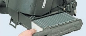
The air entering the engine cylinders is cleaned of dust by an air filter. Air filter
installed in the engine compartment on three rubber supports. The filter element is replaceable and made of special paper. To prevent contaminated air from leaking into the intake tract, there is a sealing edging at the top of the element. To replace the filter element, the filter cover is removable. The purified air passes through the mass air flow sensor through the air duct to the throttle valve.
Throttle valve
regulates the amount of air entering the engine cylinders. The damper drive from the gas pedal is cable. The damper rotates on an axis in the housing (pipe). The throttle body is secured to the receiver flange with studs. The housing has a channel for coolant. The channel is connected to the cooling system by rubber hoses. Circulating coolant through the throttle body prevents the body's internal air cavities from freezing in the winter. The housing contains fittings for connection to the absorber and the engine crankcase ventilation system.
The throttle body, with the throttle position sensor and idle speed control installed on it, form the throttle assembly.
Throttle assembly:
1 - throttle valve drive sector; 2, 4 — fittings for connection to the engine cooling system; 3 — crankcase gas outlet fitting; 5 — throttle position sensor; 6 — idle speed regulator; 7 — fitting for connecting to the adsorber; 8 — throttle valve; 9 — throttle body pipe
Air is supplied to the intake valves of the engine cylinders through the receiver and the intake manifold.
Fuel tank
steel, welded from two stamped parts. The tank is suspended from the bottom of the car on two steel clamps. The filler neck of the fuel tank is located on the right side of the vehicle and is closed with a plug. Fuel from the tank is supplied by an electric submersible fuel pump.
The pump is installed in the fuel tank. To access the pump, there is a hatch with a cover in the bottom of the car under the rear seat cushion. A strainer is installed on the inlet pipe of the fuel pump, which traps small solid particles of debris that enter the fuel tank along with gasoline. The pump is turned on by command from the ECU.
Fuel pump:
1 — protrusion for fastening the mesh filter; 2 — fuel intake pipe for connecting a strainer; 3 - body; 4 — electrical connector block; 5 - outlet (discharge) pipe for connection to the fuel module cover with a corrugated tube
From the pump, through the corrugated tube of the fuel module (see below), gasoline enters the fuel line and then into the fuel filter, where the fuel undergoes more thorough cleaning.
The fuel filter is made of paper, installed in a non-separable metal housing. The purified fuel flows through the fuel line into the fuel rail.
Engine fuel filter 11183 (1.6i):
1 — inlet pipe; 2 - body; 3 — fuel flow direction arrow (painted on the filter housing); 4 - outlet pipe
Note. The fuel filter of the 2111 (1.5i) engine has threaded connecting pipes.
The fuel rail holds four injectors and supplies fuel to them. The connection between the ramp and the injectors is sealed with rubber rings.
The fuel pressure regulator is a bypass valve that maintains in the system (fuel line) the operating pressure necessary for proper operation of the injection system.
All cars of recent years of production are equipped with a fuel vapor recovery system (in accordance with EURO II environmental requirements), where the above-fuel space of the tank is connected to the atmosphere not directly, but through the elements of this system. The system consists of a separator, safety valve, adsorber, gravity valve, adsorber purge valve, check valve, connecting pipes and hoses. The separator and gravity valve are mounted under the right rear fender of the vehicle. In the separator, gasoline vapors are partially condensed and returned back to the fuel tank. The gravity valve prevents fuel from leaking out of the tank when the vehicle turns over. The safety (two-way) valve prevents the formation of excess pressure of fuel vapor in the tank, as well as the occurrence of vacuum there caused by fuel consumption.
Location of elements of the fuel vapor recovery system in the rear of the vehicle:
1 - safety valve; 2 - separator; 3 — plug of the filler neck of the fuel tank; 4 - gravity valve
Note. The photo shows the rear bumper.
From the separator, non-condensed gasoline vapors flow through tubes and connecting hoses into the adsorber, which prevents the vapors from entering the atmosphere. An adsorber is a container where gasoline vapors are absorbed by activated carbon. When the engine is running at high crankshaft speed, the ECU sends a signal to open the canister purge valve, and gasoline vapors are sucked into the intake module receiver.
Adsorber:
1 — adsorber body; 2 - pipe for connecting the internal cavity of the adsorber with the atmosphere; 3 — adsorber purge valve; 4 — valve connecting pipe; 5 — adsorber connecting pipe
Fuel system and extending the life of the gas tank
After installing the power unit on the car, it came to a complete revision and replacement of some elements of the fuel system. The first thing I decided to do was repair the fuel tank. It was removed from the body back in the summer of 2013, and had the following appearance:
The task was to completely clean and rinse the tank inside and outside, and then paint it.
After washing the tank and visually inspecting its condition, a slight deformation of the bottom in the area of the fuel pump module was revealed. By its appearance, we can confidently say that it was formed when a car collided with a road obstacle. Straightening out the dent was not difficult; for this I used a metal rod, a hammer and a copper block used in plumbing.
In addition, I paid attention to the condition of the metal in the area of the weld along the entire perimeter of the tank. Crevice corrosion was present almost everywhere. This upset me a little, since this problem had to be fixed, and in the first minutes I didn’t even know how to do it. But, after further thinking about this issue, I came up with an idea.
The manufacturing technology of the fuel tank involves joining the parts of the body with an overlap, and applying one weld with through penetration, as shown in the following figure.
As you can see, the seam is not applied to the edge, but rather closer to the inner cavity of the tank. When it is subsequently painted, the paint is practically unable to penetrate into the gap formed between the mating parts of the body, thereby creating favorable conditions for the development of corrosion in this place during subsequent operation of the car.
The described development of events is confirmed in practice and has the following picture:
The existing crevice corrosion will eventually turn into through corrosion, which will break the tightness of the tank and lead to the need to repair it or replace it with a new one.
To avoid adverse consequences and extend the life of the gas tank, I decided to get rid of the potential source of corrosion by cutting off all the metal from the outside after the weld.
The procedure was performed with extreme caution in order to avoid breaking the seal of the tank. I cut off the main part of the unnecessary metal using an angle grinder, trying to cut at the edge of the weld or with a slight indentation from it. Then, where the use of an angle grinder posed a danger of violating the integrity of the seam, I, armed with a file with a large notch, finally removed the remaining metal until the metal overlap was completely removed. The result is a solid face without any cracks or cavities.
To check the tightness of the tank after the modification was completed, I poured a small amount of kerosene into it and installed it in a vertical position for some time, carrying out this control on each of the four faces.
The next problem I discovered, and not only with my gas tank, is the fastening of the fuel pump module. We are talking about earlier versions of tanks that use M4 threaded studs. In most cases, such a small thread, if used carelessly, quickly becomes unusable. The main reason here, in my opinion, is nuts with insufficient height, which involves too few threads. Negligent use of threads also means excessive tightening torque of a threaded connection, which is the case in our country. As a result, the threads are cut off at the place where the nut has its final position when tightened, which is what I found on several studs on my tank.
I saw the local solution to this problem as making nuts with an increased height in order to involve more threads of the fastening joint threads.
Looking ahead, I will say that before installing the pressure ring of the fuel module, I went through the threads on each stud with a die. The previously installed bushing washers were replaced with regular ones with an increased outer diameter.
The last thing left to do was paint the tank, and this should have completed its restoration. Places where the old paint had peeled off and bare metal was visible were cleaned and primed. I did not completely remove the old coating, I just gave it a matte finish for better adhesion of the new paint.
The primer was applied using a piece of foam rubber, and the paint was applied with a spray gun. To prevent it from penetrating into the internal cavity, we had to plug all the fittings with a rag, and the hole for the fuel module with a simple device consisting of a piece of cardboard, an elastic band and two wood chips.
As a paintwork I used Leningrad paints PF-115 optimum enamel, black. The application was carried out in two layers, following all the manufacturer’s recommendations. At first glance, I was pleased with the result.
The tank mounting clamps and the filling pipe were also repainted, with preliminary sandblasting and priming, since they also had corrosion, and the shield ( under the separator
) sent for powder coating.
The welded bracket for fastening the filling pipe had to be cut off, as crevice corrosion had formed between it and the pipe. After removing it, the bracket was welded back. To prevent a relapse in the future, after painting the pipe, I filled the crack with molten gun fat from Oilwright.
In the course of the work described above, the necessary spare parts for the fuel system were purchased. One of the first to be purchased was an electric fuel pump assembly 21102-062213.010 ( analogue 21102-1139009
), sold under the brand name Kaluga Electromechanical
). But it honestly says on the box: made in PRC. The reason for replacing the strictly module was the fuel level sensor ( FLS
), which gave distorted readings due to wear on the contact track, as well as the rubber damping cover of the fuel pump, which had lost its elasticity and, of course, perfectionism. Considering that the average price of a new FLS is about 500 rubles, and the fuel pumps from the old and purchased modules were later removed and sold, I considered the purchase quite rational.
To power the engine with fuel, I planned to install something more efficient. I looked towards the well-known Masuma MPU-103. I already wanted to order it from the EXIST online store through my friend CHUJOYYA, but he convincingly dissuaded me from doing so.
The essence of the belief is that there is nothing more reliable than “made in Japan”, even from a landfill. Considering the quality of the new current spare parts, I easily decided on a pump from disassembly, and CHUJOYYA placed an order in my name and address. Thanks again to him!
When dismantling the Japanese pump, I noticed the smell of unevaporated gasoline. Japanese gasoline smells much nicer than ours.
After removal, the pump had to be slightly modified by cutting off the fastening locks that prevented installation in the purchased Chinese module. Otherwise there were no problems.
Having prepared everything necessary, I began assembling the fuel module and installing it in the tank.
The tank was installed on a lift using a low trolley for more convenient orientation of the tank. Since I carried out this work without anyone’s help, the idea with the cart ended up being very useful.
I decided to replace all the fuel hoses of the system with new ones, so I immediately ordered a complete set from the AutoAll online store ( article: 21082-11041-4226/08/
). The only thing is that those hoses from the kit that are placed in the engine compartment do not have additional protection in the form of a rubber cover. If there is a possibility of abrasion of the hose, it is worth making a cover yourself, for example, from a rubber hose of a larger diameter or plastic corrugation for electrical wires.
Having installed the tank and connected the supply and discharge lines, all that remained was to install the filler neck, deal with the gasoline vapor separation system and the separator itself, since a crack was discovered on the old one, so it definitely required replacement. To study its design, it was divided into two parts:
The design is primitive, but apparently workable. I didn’t do anything fancy here, I bought all the necessary components and assembled everything according to the original scheme. The only thing is that instead of PVC hoses, I installed rubber pressure hoses with thread reinforcement, non-reinforced according to GOST 10362-76. You can read more about the gasoline vapor separation system here and here, which is what I did while studying the principle of its operation.
I would also like to draw your attention to rubber goods installed on a metal shield located under the separator:
— bushing of the outboard bearing strip (2101-2202106
) 4 things.;
— sealing ring for the gas tank filler neck ( 2108-1101085
) 1 pc.
The parts are irresponsible, they are quite rare in stores, few people bother looking for them. But still, out of necessity, some car owners acquire the desire to find them and buy them. I even came across a blog post asking for help in purchasing the O-ring mentioned above.
My shield ring definitely needed replacing.
In theory, the fuel system was now ready to go. Before starting the engine, I planned not to connect the supply hose to the fuel rail, but to check the operation of the pump and at the same time flush the line, despite the fact that this had already been done in the record of my BZ.
You might be interested in reading:
- The heating system for the VAZ 2115, its design and repair. Connection diagram for the VAZ heating system. Mounting block. Ignition. Unloading ignition relay. Heater motor switch. Additional resistor. Stove motor. Control button...
- Steering gearbox VAZ 2107 - design, replacement and repair Where is the steering gearbox located? It is located in the engine compartment and immediately under the vacuum brake booster (Indicated by a blue arrow), for…
- VAZ 2107 stove - design, repair, modifications The VAZ 2107 stove creates and maintains a comfortable air temperature in the cabin and prevents the windows from fogging in cold and humid weather...
- Starter for VAZ 2114 its design and repair Principle of operation After turning the ignition key, current is supplied from the battery to the relay. The Bendix drive is connected to the flywheel. The starter starts the engine...
- Oil pressure sensor VAZ 2115 - replacement and repair Types of oil pressure sensors It is believed that in order to be able to correctly replace any part on a car you need to know its principle...
Features of the 2111 (1.5i) engine power system
Location of elements of the 2111 (1.5i) engine power supply system in the engine compartment:
1 - receiver; 2 — vacuum supply hose to the fuel pressure regulator; 3 — throttle assembly; 4 - fuel rail; 5 — fuel pressure regulator; 6 — air supply hose to the throttle valve; 7 - adsorber; 8 — air filter; 9, 10 and 11 — hoses of the crankcase ventilation system; 12 — throttle valve drive cable; 13 — diagnostic fitting
Fuel pump
combined with the fuel level indicator sensor into a single unit -
a fuel module
(often called an electric fuel pump). The pressure pump delivers fuel from the tank through the fuel filter to the fuel rail.
Engine Fuel Module 2111 (1.5i):
1 — fuel level indicator sensor; 2 — connecting block; 3 — inlet pipe; 4 - outlet (discharge) pipe; 5 — module cover; 6 — module cover guide; 7 - electric fuel pump in a plastic casing; 8 - intake chamber
Fuel rail for engine 2111 (1.5i) complete with injectors:
1 — diagnostic fitting; 2 - fuel rail; 3 — fuel supply tube to the fuel rail; 4 — fuel pressure regulator; 5 — tube for draining (draining) fuel into the tank; 6, 7, 8 and 9 - injectors
Fuel pressure control
installed on the fuel rail. Excess fuel is returned to the tank through the fuel return line.
Engine power supply system diagram 2111 (1.5i):
1 - nozzle; 2 - fuel rail; 3 — diagnostic fitting; 4 - adsorber; 5 - check valve; 6 — throttle assembly; 7 - gravity valve; 8 — safety (two-way) valve; 9 - separator; 10 - filler pipe; 11 — fuel filter; 12 — fuel drain line; 13 — fuel line hose connecting the outlet pipe of the fuel module to the fuel filter; 14 — fuel module; 15 — fuel tank; 16 — fuel line connecting the fuel filter to the fuel rail; 17 - fuel pressure regulator
WE RECOMMEND:
The fuel filter plays a rather important role in the car's power system. Regardless of which engine (diesel, carburetor or injection), or which car (domestic or foreign car), such a mechanism is installed on all fuel systems. Let's look at the principle of operation and design of the fuel filter, using the example of a VAZ 2114 car.
Features of the engine power system 11183 (1.6i)
Receiver
engine 11183 (1.6i) is made of plastic.
Engine Intake Module 11183 (1.6i):
1 — flange with an o-ring for fastening the throttle pipe; 2 - receiver with o-rings for connection to the inlet pipeline
Engine Fuel Module 11183 (1.6i):
1 — inlet pipe (for supplying fuel to the pressure regulator); 2 - outlet (discharge) pipe; 3 — module cover; 4 — fuel level indicator sensor; 5 - intake chamber; 6 — module cover guide
Fuel pump
combined with a fuel level indicator sensor and a fuel pressure regulator into a single unit -
a fuel module
(often called an electric fuel pump). Fuel from the pump (through the outlet pipe of the fuel module) enters the fuel filter. Purified gasoline is again supplied through the fuel line and through a tee to the inlet pipe of the fuel module, and then supplied to the fuel rail.
Engine fuel pressure regulator 11183 (1.6i):
1 — hole for dumping excess fuel; 2, 4 — sealing rings; 3 — holes for supplying fuel to the regulator; 5 — body; 6 - terminal for connecting the regulator to ground
Fuel rail for engine 11183 (1.6i) complete with injectors:
1 — diagnostic fitting; 2 - fuel rail; 3 — fitting for connecting to the fuel line; 4, 5, 6 and 7 - injectors
Excess fuel is released through the pressure regulator into the tank. The fuel pressure regulator is installed in the fuel module cover.
Engine power supply diagram 11183 (1.6i):
1 - nozzle; 2 - fuel rail; 3 — diagnostic fitting; 4 - adsorber; 5 - check valve; 6 — throttle assembly; 7 - gravity valve; 8 — safety (two-way) valve; 9 - separator; 10 — fuel line tubes connecting the fuel module to the fuel filter; 11 — fuel module; 12 — fuel filter; 13 - filler pipe; 14 — fuel tank; 15 — fuel line connecting the fuel module to the fuel rail; 16 — metal fuel pipe; 17 — connecting hose; 16 - fitting for connecting the fuel rail to the fuel line
Analysis of cars selling fuel rail for VAZ (Lada) 2114 in Moscow
- Audirazbor Rating: 5.0
/5 – 4 ratings - Mytishchi district, Dmitrovskoe highway, Gribki settlement, uch. 15A.19
- +7
- Rating: 4.6
/5 – 10 ratings
- Rating: 3.9
/5 – 11 ratings
- Rating: 4.4
/5 – 8 ratings
- Rating: 4.0
/5 – 11 ratings
- Rating: 4.4
/5 – 8 ratings
- Rating: 4.2
/5 – 10 ratings
- Rating: 4.1
/5 – 8 ratings
- Rating: 4.6
/5 – 7 ratings
- Rating: 4.5
/5 – 6 ratings
- Rating: 4.5
/5 – 4 ratings
- Rating: 4.5
/5 – 6 ratings
123…34
Popular companies
- Best Auto Parts 4.4
/5 – 8 ratings - Butyrskaya street, 86Bs7
- +7,,
- 4.1
/5 – 8 ratings
What gasoline to use
This question is one of the most pressing for domestic car enthusiasts, because, on the one hand, gasoline prices are constantly rising, and you want to save money. But, on the other hand, the quality of fuel at most gas stations leaves much to be desired, and you don’t want to fill your car with anything.
That is why you should adhere to the basic principle - the 14th gasoline in the passport indicates exactly 95th gasoline, which means that this is what you need to fill it with.
Gasoline for VAZ 2114
As for bad fuel, if possible, you should choose from the nearest gas stations those that have the highest quality gasoline (based on the behavior of the car after refueling), and then refuel only at these stations.
True, you can also notice that many owners of the 2114 fill it exclusively with 92-grade gasoline and, according to them, do not see much of a difference in the operation of the car and in the rate of wear of the components of the gasoline system. Whether to follow these tips or use exclusively suitable fuel is up to everyone to decide for themselves.