The absence of a sound signal on a car is a malfunction that affects traffic safety. The ability to promptly warn or attract the attention of pedestrians, as well as other road users, directly with the horn, can help avoid creating an emergency situation or an accident.
A malfunction such as the absence of a sound signal on VAZ family cars is quite easy to diagnose and repair with your own hands. To do this, you need to study the connection diagram (it is very simple) and follow the instructions to carry out the necessary checks.
Installation of sound signals from Volga
Many owners of VAZ 2109, 2108 are not satisfied with the sound of the standard horn of their car. An excellent replacement for the standard nine signal can be the option discussed here for installing a sound signal from the Volga. Many, including the author, have already completed this not at all complicated installation, and do not regret the time and money spent, especially since this modernization is more than compensated by the awareness of the fact that his car has become a little closer to ideal, and is ready for it immediately show it to everyone! So, for this installation we will need the following materials:
- signals from the Volga with a “mass” on the body
- relay type 90.3747 with mounting flange
- relay socket
- female terminals wide
- heat-shrinkable tube (HERE)
- stranded wire with a cross section of 2.5 mm. sq.
- blade fuse block
- 20 A fuse
- metal corner
Spare parts for modification First of all, remove the ground terminal from the battery.
To access the standard signal of the VAZ 2109, remove the radiator grille, unscrew the standard signal along with its fastening bar. The signal ground wire is attached nearby, we dismantle it too.
At home, we will first prepare the mounting of signals from the Volga based on a steel angle purchased at any building materials store. We will attach the signals to the standard place where the original signal is attached. We mark the corner at the installation location, saw it off, and drill holes for attaching signals from the Volga. It is also advisable to paint the corner to protect it from corrosion. Next, we attach the signals to the corner. The signal fastening bolt is also a “ground”, so it is necessary to ensure its electrical contact with the angle, for example, by securing the Volgov signals through a castle washer.
We fasten the corner with the signals to the bolt securing the standard Samara signal through a castle washer to ensure contact of the corner with the ground. It is possible that the bolts securing the Volgov signals on the corner will touch the radiator; in this case, we put washers, thereby moving the corner with the signals away from the radiator. Do not forget about the need to preserve the corner with the car body (“ground”). That's it, the mechanical part is over, let's move on to the electrical part.
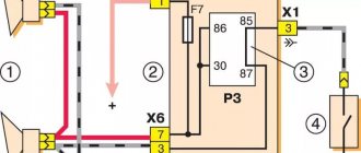
Signals from the Volga to the VAZ 2109 are connected according to the following scheme:
Electrical diagram for connecting Volgov signals to Lada Samara
We crimp the ends of the wires with appropriate terminals. We hide all connections in a heat-shrinkable tube.
The relay can be mounted on the back of the radiator frame, next to the headlight.
Additional signal activation relay
We fix the ground wire of the relay (pin 86) under the flange of the relay mounting to the car body through a castle washer to ensure electrical contact, having previously installed a tip with a fastening eye on the wire.
We connect the wire from the fuse (30th contact of the relay) to the positive terminal of the battery.
Powering signals directly from battery
The final result is how signals from the Volga look on the “nine”:
Reinstall the radiator grille:
That's it, the Volga signals are installed, let's buzz and enjoy the noble sound!
You can adjust the sound of signals from the Volga by rotating a special bolt on their body. Also, don’t forget about anti-corrosion protection; you can simply coat all bolted joints with Litol.
Volga signals on the VAZ 2109 and its modifications can be installed without using a relay, by directly connecting to the power wires of the standard signal; the standard signal is already connected through a relay in the fuse block. But this method has disadvantages. The positive power wire of the standard signal is very thin; the signals will not operate at full power due to the voltage drop in this wire, because The Volgov signal is more powerful than the standard one. The power supply circuit for the standard signal is protected by fuse No. 8 in the fuse block, and the cooling fan power supply circuit is also protected by the same fuse. Due to the fact that Volgov signals consume more current (14 A) than the standard one (5 A), this fuse will burn if the fan and Volgov signal operate simultaneously, and the corresponding tracks on the printed circuit board in the fuse block may also be damaged.
Why do you need a relay?
The seller persistently sold me a relay for 40 rubles, saying that I couldn’t live without it. But in the end, it worked out without him.
What is the point of a relay?
First version (MYTH) The point is that the VAZ and Volgov circuits for connecting sound signals are not the same. Volgov's horns take ground from the body, while VAZ's horns take ground from the connected wire. According to the sellers, when we press the beep, we close the ground (-) and not (+). Therefore, if you connect without a relay, the horn will work constantly. But in reality, everything turned out quite the opposite, which made the work easier. Therefore, we proceed as follows.
Second Version (more real). Volgovsky buzzers consume a current of 14A, and a standard buzzer 5.5A. Due to excessive load, the fuse may melt, and if you set its rating higher, the tracks on the board will melt.
If you want to install a relay, install it, but I didn’t install it, because... The loads applied to the beep are not constant and short-term.
Examination
It is a mistake to assume that damage to high-voltage wires does not in any way affect the condition of the module itself. Many people think of simply replacing high-voltage elements, but in reality they will still have to change the module.
This is explained by the fact that damaged or defective wires direct the wrong current, the configuration of which does not correspond to the necessary parameters. As a result, the spark hits inaccurately or ineffectively, causing the module to burn out and become unusable.
In general, the best option for checking the ignition module on a VAZ 2114 is to use an oscilloscope. But, firstly, not every driver has it, and secondly, few people can use them. Therefore, we will carry out the check using improvised means:
- 12-volt light bulb;
- Tester (available for little money at any auto parts store).
Let's start with preliminary manipulations with the accompanying elements of the ignition module.
- Check the wiring harness. It is disconnected and the voltage indicator is checked.
- To do this, fix the tester on contact A, and connect the other terminal to engine ground.
- In normal condition, the voltage reading will be 12V.
- If there is no voltage, most likely the fuse has blown.
- If everything is fine, transfer the terminals of your tester to contacts A and B, start the car. In this case, the starter should turn and the 12-volt light should blink.
- In the absence of these phenomena, we can talk about the presence of a break in circuit A of the contacts.
Next we go to the ignition module itself.
There are several ways to check the condition of your unit. Therefore, let's look at each of them.
- Set the tester to ohmmeter mode. Use it to measure the resistance on the high-voltage lines going to cylinders 1 and 4, and then, by analogy, to the wiring of cylinders 2 and 3. In normal condition, the device will give you readings from 5.2 to 5.5 ohms.
- Give the device a gentle tug. Thus, you will shake the wiring block and the module. Moreover, this must be done in the operating mode of the power unit. If the device works without obstruction when loosened, everything is fine, you are lucky. If not, you will again have to study the condition of the wiring.
Third way
The third method is considered the simplest, since it involves replacing your device with a similar one that works exactly. But to do this, you have to find a full-fledged twin. We are talking about an ignition module from a car similar to yours in terms of year of manufacture and power unit used. It’s just that 1.5-liter engines have modules, and 1.6-liter engines have coils.
But to replace a module with a module, you will have to first dismantle yours. This is done as follows:
- Remove the negative terminal from the battery, which will allow you to turn off the power to the car;
- Disconnect four high voltages from the ignition module;
- Disconnect the wire block. To do this, you need to release the special clamp that holds the block on the module;
- Next, unscrew the three nuts. With their help, the module is held on the bracket;
- There are three long pins on the bracket, from which the module can simply be pulled off.
Having dismantled your module, you can put another unit in its place, thereby verifying the functionality of that one and the malfunction of yours.
Connecting autorun
The VAZ-2114 models use an ignition switch with three terminals - 15 (blue wire), 30 (lilac) and 50 (red). Terminal 30 is connected to the battery. When you turn the key, blue wire 15 is connected to this terminal. The third terminal is responsible for the starter.
As it is written in the instructions, it is quite possible to power the alarm from contact 30, from which the lead is made. And the cable from connector X1, yellow, is connected to connector 15.
After all the actions taken, the connection of the tachometer remains. In this case, a loop antenna and a reading device are combined. Connector X3 has a gray-black outgoing wire. It is connected to the tachometer as shown in the VAZ dashboard diagram:
This will allow the alarm to control the speed. And at the very end we connect the ground from the main unit. This is a black cord from connector X3.
Repair of sound signals on VAZ cars of various modifications
Sound signals, as such, are not among the most complex elements of a car, however, traffic safety and the ability to avoid emergency situations largely depend on their good condition. Be that as it may, even with all its simplicity of design, the sound signal (including on various modifications of the VAZ) may stop working and if such an unpleasant situation arises, you can most often cope with the problem on your own, it is enough to have the appropriate diagram at hand and follow a few simple recommendations.
In general, the connection diagrams for the sound signal on the VAZ “classic” series and on subsequent front-wheel drive models are quite similar and the main differences relate to the relay markings, as well as the location of the fuse. Among other things, on the earliest versions of the VAZ (2101, 2102, 2103 and a number of modifications 2106), the electrical circuit of the sound signal or the presence of a unloading relay is not provided at all.
VAZ sound signal circuit without relay
- Accumulator battery;
- Fuse (one for two signals), located in the fuse block;
- Horn switch in the form of a button on the steering wheel;
- Generator.
VAZ sound signal circuit (2104 – 2107, and also 2121) with relay
- Accumulator battery;
- DC generator;
- A fuse common to the two signals (located in the fuse block);
- Control relay (usually RS-528).
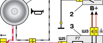
Sound signal diagram for VAZ Samara (2108, 2109, 21099), as well as for VAZ 2113 - VAZ 2115
Sound signal circuit for VAZ 2110 - VAZ 2112, as well as all existing modifications
1.Universal sound horn;
2. Signal control key located on the steering wheel;
3. Fuse in the mounting block (again, there is no relay).
Wiring diagram for the sound signal on the VAZ Kalina and VAZ Priora
- Mounting block with fuse and relay (in the documentation it is sometimes called a control and comfort unit);
- Sound signal control key;
- Universal sound signal.
Possible causes of audio signal failure and methods of elimination
The most common reason for the loss of a sound signal lies in the imperfection of its design and poor protection from moisture and dirt. In other words, during operation, oxidation of the contacts occurs, as well as blocking of the sound membrane (as a result of which there are no vibrations and the necessary sound effect). Such failures can often be eliminated by adding a small amount of WD-40 or its equivalent to the signal, but in order to achieve a guaranteed and long-lasting result, it is still recommended to disassemble the signal and the control key in order to perform more thorough cleaning.
Among other things, on cars equipped with two signals (as a rule, they are of different tones), when one of the elements fails, a significant weakening of the output sound power occurs, and here you will have to determine the failed signal and change it. By the way, many signals are equipped with special adjustment controls, and if wheezing, grinding and other extraneous sounds occur, you can improve the sound quality by rotating the adjusting screw. You can also try to rip off the “soured” membrane by rotating it.
Troubleshooting Electrical Circuits
when there is no signal at all:
— We check the presence and condition of the “ground”, as well as the supply voltage directly on the signal (it is necessary to take into account that on early VAZ models the “plus” “hangs” constantly, and control is carried out by closing the “minus”). If there is a stable plus and a minus appears when the key is closed, the signal itself is faulty and should be changed.
— We check the supply voltage in the sections of the circuit with the fuse, the power relay and the mounting block as a whole;
— We evaluate the condition of the contacts and the overall “mass” of the control button and eliminate all traces of oxidation.
The signal periodically disappears, and extraneous sounds can be heard when sounding:
— We carry out debugging using the adjusting screw.
When turning the steering wheel, the signal begins to sound spontaneously:
— Most likely, the steering column switch is installed incorrectly (too close to the steering wheel);
— Alternatively, there is a short circuit to the ground on the steering column (via the signal control circuit).
Source
Why the sound signal does not work on the VAZ-2112 photo and video
Operating a car with a faulty sound signal is prohibited. At the same time, on cars of the “tenth” family, the horn may stop working for no apparent reason. Potential “+12” is connected to one of the horn wires. And the second terminal should close to ground when the key is pressed. Let's look at why the signal on the VAZ-2112 does not work, and for this we will check the control points.
Sometimes it is possible to restore contact with ground without removing the steering wheel. An example is shown in the video.
Features of the VAZ-2112 electrical circuit
The owners of cars of the “tenth” family are to some extent lucky: there is no relay in the horn circuit, but only a switch. The proof is given below.
Standard wiring diagram
The first step is to check fuse F7. In the mounting block it is in the top row (seventh from the left).
Voltage “+12” is applied to one of the fuse terminals. Check it out!
If the fuse is good, potential “+12” should be at one of the horn terminals. Let's take a look under the hood...
Audio module connector
Disconnect the connector and check both terminals with a tester. We connect the second probe of the voltmeter to the negative of the battery.
The standard reason why the signal does not work on the VAZ-2112 is this: the “positive” voltage is connected, but the contact with the “ground” is broken. Most often the problem lies in the switch.
We diagnose the sound signal
It all starts with the connector pins:
- Let's say the voltage “+12” is not caused on both contacts. Then look for a short circuit or break point, starting from terminal 6-Ш5 (diagram above).
- If positive voltage is received, check the second terminal. It will contact ground when you press the horn button. During this check, the battery must be disconnected.
- If the previous two steps are completed successfully, then voltage is supplied to the horn. It may need to be replaced or the contacts cleaned.
By the way, in “step 2” it is recommended to rotate the steering wheel - contact may be broken at certain angles of rotation.
Removing the steering wheel
If “step 2” is not successful, you need to remove the steering wheel. The two copper strips should “close” when pressed - everything is clear here. The test is carried out with an ohmmeter, and if necessary, the switch is replaced.
Steering wheel after dismantling
When the steering wheel is removed, you can clean the contact tracks. The wire contacts in the column must also be clean.
Dismantling from start to finish
First you need to unscrew the two screws under the trim. Having removed the plastic, you can see the contact plate - perhaps that was the problem.
First step in dismantling
Try cleaning the contacts and performing “step 2” again. If there is no result, take a 24mm wrench and unscrew one nut (not all the way).
The steering wheel needs to be knocked off its splines
The steering wheel is pushed towards itself. And then the nut can be unscrewed completely.
When installing, follow one rule. The protrusion on the bracket should fit into the slot made in the plastic ring (see photo).
Steering wheel installation (first step)
How to remove a faulty signal (horn)
There is a single module mounted under the radiator grille. To remove it, unscrew one nut (key “13”). First disconnect the connector.
Dismantling, adjustment before installation
It will be necessary to remove the grille. This action is difficult to perform on both the “Ten” and even on the VAZ-2112, and the signal may not work due to faulty wiring. First achieve what was discussed in “step 3”. And only then, if necessary, proceed with replacement.
One adjusting screw is fixed to the horn body. Set it to the middle position and check.
Removing the radiator grille
- Taking the “10” key, unscrew the two screws on top (as in the photo). You can't remove the grill right away.
Self-tapping screw for radiator grille fastening
Using both hands, applying equal force on both sides, pull the grill upward. In this case, the two lower clamps should not break.
An important fastening element is the clamp.
Installation will be easier - there is no risk of breaking the clamps.
Settings
Only autorun functions can be configured. To activate programming mode:
- Disable security
- The ignition key is set to position 0.
- Then press the Valet key six times in the main block.
- Turn on the ignition
- After six beeps, use the same key to select the desired function, and use the key to
- key fob select the desired value.
The optimal settings for VAZ - 2115.2114 will be the following: function 12 - set to value 3, function 11 - value 4, function 9 - value 3. To select value 4, press and hold the third button until the melody is played. After playing, press it again.
To check the correct connections, perform the following steps:
- Disconnect the yellow cord from block A91 to terminal 15 for a while.
- The engine is started using the ignition key
At the same time, the alarm indicator should blink.
Didn't find the information you are looking for? on our forum.
Messages 5
- Tamman
- User
- Offline
- Registered: 2009-02-13
- Posts: 30
- Reputation:
Topic: Signal Problem
The background is this: a couple of times when I was standing in the yard it started to honk (not an alarm, but a signal (on the steering wheel)), I ran and turned off the battery.
1) changed the fuse and relay, cleaned the fuse block completely (it went away but only for a while) - that’s not the problem
2) I changed the steering wheel, the adapter for the steering column switches (the contacts were worn out badly), the steering column switches (I was still assembling them, but this might be the problem) - everything seemed to be fine, but today, when I parked, at the end of the parking lot the steering wheel made one turn to the left , turned it off and started beeping again.
About a month ago, my heater radiator was replaced and, accordingly, the panel with the steering wheel was removed. So (see photo below), perhaps these 2 wirings were mixed up. Today I noticed something that if you remove the left one (black) and press the signal, it still works. If the right one (gray with a black stripe) is placed on the left contact (and the black wire can be worn or not), then it beeps even without pressing the steering wheel.
So, please explain what kind of wires these are and which one goes where? As far as I understand, the black wire goes to the left contact (this is the “-“ ground), the gray wire with a black stripe goes to the right contact (this is the “+”). Correct me if I'm wrong.
The annoying thing is that if the gray wire with a black stripe is on the right contact, and the black wire is not connected anywhere, then when pressed it still beeps.
Replacing the block
There are malfunctions in which car enthusiasts have to dismantle the mounting block to check it. These malfunctions are associated with the following reasons:
- PP breakdown;
- relay failure;
- damage to conductive paths;
- contact damage.
To remove the power supply, you need to remove its cover (you can read how to do this above), disconnect all the wires from it. Further, if the unit is completely faulty, it can be easily removed and a new one installed by reassembling it in the reverse order.
Advice! When disconnecting, be sure to mark the wires so as not to forget what to connect and where when reassembling.
We have discussed how to diagnose problems with PPs and relays, now let’s see how to identify problems with conductive paths and contacts:
- Even an experienced electrician has a hard time identifying this type of damage. Even if the problem is identified, soldering has to be done with very high precision, which requires high qualifications and a lot of time;
- The main problems associated with contacts in the VAZ 2114 power supply arise due to corrosion and contamination of the contacts. You can usually just clean up the contact with a knife or sandpaper. If it breaks off, you can solder it, but this is very labor-intensive and difficult; one wrong move and replacing the block cannot be avoided.
It’s always better to see once, so look at this review of the VAZ 2114 fuse box:
Signal from Volga to VAZ 21099 — Lada 21099, 1.5 l., 1999 on DRIVE2
Hi all! About a year ago, the signal began to close when turning the steering wheel; it went off at almost every intersection when turning, unnerving both me and those around me. I didn’t do anything, I just turned off the power from the signal itself and removed the relay. I drove like this for almost a year. In the summer I installed the steering wheel under the viburnum (I already wrote about this in the BZ), but I didn’t connect anything, I was already used to driving without nerves and unnecessary beeps.
I once went to a store for auto chemicals, there wasn’t much, but I noticed the GAZ spare parts department. I read about Volga signals on D2, let me think I’ll go and see how much they cost... The price tag was a little upsetting. 460 for one “shell” (two included in the set), I thought, since I didn’t take the chemistry, I’ll at least buy a signal. Thought through, done.
Photo from the internet. I bought the same ones
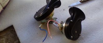
I painted the chrome part black so that it would not rust and be conspicuous. We also purchased the necessary connection parts shown in the picture:
necessary spare parts, + fuse and additional. wires to extend the standard signal wire
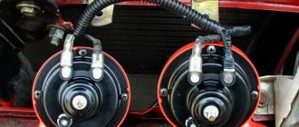
Having drilled holes on the “TV”, I installed the signals using plates
placed it next to the headlights so as not to cover the radiator
I extended the standard signal wire with wires (connected it through a chip so that there were no unnecessary cuts), connected it to the relay. I connected a fuse between the battery and the relay:
TO
I attached the relay and the ground to it immediately
don't pay attention to the radiator))
General form
You can barely see behind bars. Now, at every successful opportunity, I don’t restrain myself from “blowing”... I really like the sound, not like standard crap, and in my opinion it will last longer than the pneumatic horns that have been installed on every third car lately
Thank you all for your attention! And good luck on the roads
Tapping into wires
Next to the driver's door, there are two wire harnesses running right along the floor. One of them has a cable coming from the parking brake and two wires to the turn signals. The second harness contains the door switch cable. This is where you need to start connecting. To do this, remove the sill trim along with the side panel. They are attached using self-tapping screws that must be unscrewed. Having done this, you can see the wiring harness shown in the photo:
This harness goes to the dashboard. We are interested in the door switch cable. If a 1N5401 diode is inserted into the wire break, the current should flow towards the limit switches. And the second diode 1N4001 is connected as shown in the figure.
The following figure shows the second harness:
At the same time, taps are made from the blue cables and the cords are pulled to the place where the alarm will be installed. And the handbrake wire is cut, and a 1N4001 diode is soldered into the cut with the cathode towards the switch.
Possible malfunctions: signs and causes
There are several signs of a malfunctioning sound signal on a VAZ 2110 or 2112:
- The sound signal has disappeared. The driver presses the steering wheel or the corresponding button located on it, but there is no beep.
- The beep appears and disappears. When the driver presses the steering wheel, the signal may start to work, but then immediately disappears.
There may be several reasons why the horn refuses to function:
- One of the most common reasons is the failure of a safety device. In this case, the integrity of the horn itself will not be compromised, which greatly simplifies the repair procedure.
- Failure of the horn itself. If after replacing the safety device the sound does not appear, you can try to check the functionality of the horn by dismantling it and directly connecting it to the battery. If the device is working, then when connected to the battery it will begin to emit a corresponding signal.
- The reason may also be a short circuit in the vehicle's on-board network.
- Another cause of the problem may be worn out clamping contacts located on the steering column. This problem often occurs in the cars of our compatriots. In any case, the clamping contacts wear out over time due to use; this cannot be prevented. As an option, you can try to increase the service life of the contacts; to do this, they need to be treated with graphite lubricant from time to time.
- Worn slip ring on the steering wheel. As stated above, there is no escape from wear and tear, so sooner or later every car owner will face such a problem. As in the previous case, you can try to increase the service life of the slip ring by applying graphite lubricant to it.
- Oxidation of contacts on the steering wheel. With prolonged use, deposits will begin to accumulate on the internal contacts, which makes it impossible to transmit the impulse to activate the horn.
Connection diagram
After carefully studying the alarm installation instructions, you can find the following connection diagram:
In this diagram, the designation X2 indicates a six-pin connector. It must be connected according to the diagram above. If you need to install an additional actuator, then it is better to use the diagram given in the instructions.
Now let's figure out how to connect the door sensors. For this purpose, there is a special wire in the connector marked X3.
How to install Volgov signals?
- Open the hood.
- Remove the black decorative trim (by unscrewing 4 screws) between the bumper and the TV.
- Having gained access to the standard horn, remove it by unscrewing the screw with a key set to “13”.
- We cut off the plug of the old wiring, find the positive wire, connect it to the plug of the new horn and short it to ground. If there is no signal, and it appears only after pressing the button, then this connection method is correct. If you decide to install a relay, I have attached a connection diagram that makes everything clear.
- After removing the old beep, two plates remain free, so we will install a new signal on them.
- We connect it to the common positive wire, carefully isolate everything, including the mass of the cut plug.
Important! The “snails” need to be installed with the mouthpiece down so that water does not flow into them, and if it gets in, it immediately drains off
Terms
A fuse is a switching device designed to protect an electrical circuit from overheating.
When current flows through the fuse above the permissible values, its fuse-link burns out, thereby breaking the electrical circuit.
Rated current is the current at which the fuse is capable of operating without load.
The fuse link is the part of the fuse that blows due to exposure to greater current.
Relay - a relay is a switching device designed to relieve contacts on a button. The operating principle of this device is based on the law of electromagnetic induction.
The relay has several selection parameters. This is the current at which the contacts will not melt and heat up; it is called the rated current of the relay, as well as the number of contacts.
The signal of VAZ 2109, 2108, 21099 does not work?
Owners of VAZ 2109, 2108, 21099 cars often encounter the problem of a non-working signal. Don’t rush to go to the service center, let’s check the signal and repair it ourselves.
There are several faults here:
— the signal itself has failed
— relay contacts or wires have oxidized
— the holder of the contact plate of the sound signal broke off
Let's start checking.
First of all, we climb under the hood into the fuse box and look at fuse F5, if it is intact, check relay K6.
If the fuse is intact and the relay is ok, we move on. If not, change the relay and fuse.
We have determined that the relay or fuse is OK, now we need to check the horn itself. For this we need 2 wires. We put the wires on the contacts of the sound signal, and the other ends on the battery - if the sound signal device is in working order, you will hear a sound.
Those. The problem is either in the wiring or in the contacts under the steering wheel.
If the device does not make a sound, it should be replaced with a working one.
We heard a beep. Let's dig further. We go into the car interior and remove the steering wheel cover.
Next, remove the steering column cover
And there we see a contact plate and two contacts.
We close these two contacts with a screwdriver and if we hear a sound signal, loosen the bolt securing the contacts to the steering column, move them towards the driver, tighten them and check the signal.
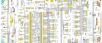
99% of a hundred the problem lies in this contact plate. If the signal never appears. We check all contacts and connections of the wires responsible for the sound signal in accordance with the diagram. A detailed wiring diagram for the VAZ 2109i is shown on this page
Connecting the central lock
First you need to study in detail the connection diagram for the central locking on a VAZ car - 2115,2114. Finding it is not a problem by searching on the Internet.
The central locking control module is located on the left under the dashboard. Looking there, you will find six wires coming out of the module housing. To install the alarm, you must disconnect the blue and brown cords. As a result, we get a connection corresponding to the following diagram:
Before connecting the alarm, you should make sure that it is not a toggle switch installed on the driver's door, but a standard actuator with five outputs. Otherwise, you will need to install an actuator, which is quite problematic.