05/08/2020 853 Electrical wiring and electrical circuits
Author:Ivan
VAZ-1111 especially small class passenger cars are equipped with 12-volt electrics with a negative terminal connected to the car body. The cars were equipped with carburetor and injection power units, which had little effect on the location and purpose of the circuits. The VAZ-1111 electrical circuit, which is basic for all versions of the Oka, can be used when repairing a car of any year of assembly.
[Hide]
What is included in the Oka electrical circuit?
The vehicle electrical system includes the following components:
- contactless ignition system;
- ignition switch with contact group and auxiliary relays;
- alternating current generator with built-in control unit;
- an electric DC motor used to start the power unit;
- external lighting and alarm system, together with wiring and controls;
- a sound signal warning other road users;
- front and rear window cleaners and washers;
- electric heating of the glass surface on the tailgate;
- control of the air supply system through the heater;
- instrument cluster with control indicator lamps;
- A fuse block that protects circuits from excessive current (caused by a short circuit or component failure).
Voltage sources for electrical operation are:
- Battery located in the engine compartment. The device is used to start the power unit and provide electricity to consumers when the engine is not running.
- A generator driven by the crankshaft of a motor. The product is designed to replenish the battery charge and ensures the operation of the electrics while the car is moving.
Division by function
As for functions, all electrical equipment is divided into systems that perform specific tasks:
- Take part in the operation of the engine;
- Ensure traffic safety;
- Create comfortable conditions;
There are also systems that are aimed at maintaining the functionality of the electrical circuit itself.
Systems responsible for engine operation
The ignition system takes part in the operation of the power unit and its task is to generate a spark in the engine cylinders to ignite the air-fuel mixture. The components of this system are a switch, a spark torque sensor, a coil and spark plugs. The system is turned on using the ignition switch. All of these components are connected by one circuit, the diagram of which is shown below:
The second system related to electrical equipment and working with the engine is the starting system. To start the engine, a power electric motor is used - a starter, controlled from the same ignition switch. Its scheme is as follows:
The cooling system fan is also related to the engine.
Systems responsible for safety and comfort
Electrical equipment that ensures traffic safety includes:
- Light and sound alarm (turn signals, brake lights, reversing lights, sound signal);
- Main light (headlights, PTF);
- Heaters, glass cleaners and washers;
These devices are combined into several systems. Below is the power supply diagram for only one of them - the turn signals:
Since the Oka is a budget car, there are not so many electrical appliances that create comfortable conditions for the driver. These include a stove (which includes an electric fan motor), an interior lamp and a cigarette lighter.
Note that the stove, in addition to creating convenience, also affects traffic safety - it heats the windows in winter.
Since devices responsible for traffic safety and comfort are not always in demand, they are turned off by default and are activated using switches.
The on-board network also includes a battery recharging system, that is, a component whose task is to maintain the functionality of electrical equipment. Its connection diagram is as follows:
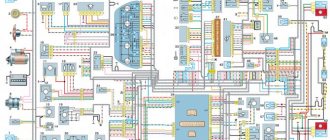
Electrical diagram of VAZ-1111 with symbols
Electrical diagram of VAZ-1111, part 1
Electrical diagram of VAZ-1111, part 2
Electrical diagram of VAZ-1111, part 3
Electrical diagram of VAZ-1111, part 4
List of elements indicated in the diagram:
- 1 — side turn signal repeater located on the front fender;
- 2 — front direction indicator;
- 3 — head lighting device;
- 4 - electric motor used to drive the radiator cooling impeller;
- 5 — warning sound signal (horn);
- 6 - temperature sensor, which ensures that the cooling system impeller is turned on;
- 7 — motor for driving the front window washer pump;
- 8 — distribution sensor of the ignition system;
- 9 — lead-acid battery;
- 10 - electric motor for starting the engine;
- 11 — ignition system controller;
- 12 — spark plugs installed in the cylinder head;
- 13 — ignition system coil;
- 14 — alternating current generator;
- 15 — liquid temperature indicator in the cooling jacket;
- 16 - control sensor that determines emergency oil pressure in the engine;
- 17 — connector for installing a portable lamp;
- 18 — windshield wiper operation controller;
- 19 — indicator sensor of the fluid level in the hydraulic brake drive system;
- 20 — brake pedal position limit switch;
- 21 — motor for driving the trapezium wipers on the front window;
- 22 - electromagnet located in the carburetor valve;
- 23 — limit switch responsible for the operation of the reverse gear signals;
- 24 — starter controller;
- 25 — headlight control relay (low beam);
- 26 - similar unit for high beam;
- 27 — controller of direction indicators and emergency lights;
- 28 — cigarette lighter socket;
- 29 — speed switch for the heating system motor;
- 30 - additional resistor that determines the rotation speed of the heater fan impeller;
- 31 — external lighting operating mode switch;
- 32 - fuse block;
- 33 — additional protective element for fog lamps;
- 34 — rear window heating control controller;
- 35 - start relay, necessary for the operation of the cooling system fan;
- 36 — control relay for the control indicator of the position of the parking brake lever;
- 37 — control of the rear window cleaning system (together with the washer);
- 38 — glass heating operating mode switch;
- 39 — rear fog light button;
- 40 — indicator of the open starting valve in the carburetor;
- 41 — alarm control button;
- 42 — ignition switch;
- 43 — distribution relay of the ignition system;
- 44 — heating fan impeller motor;
- 45 — indicator of the amount of gasoline in the tank;
- 46 — interior lighting switch located on the central pillar;
- 47 — instrument cluster;
- 48 — front wiper control;
- 49 — turning on the windshield washer;
- 50 — horn control button;
- 51 — lever for changing the operating modes of the head lighting;
- 52 — direction indicator control lever;
- 53 — limit switch, responsible for indicating the position of the parking brake lever;
- 54 — interior lighting lamp;
- 55 — limit switch located behind the carburetor choke control button;
- 56 — motor for driving the glass washer pump on the rear door;
- 57 — stern canopy;
- 58 - fog signal, located on the rear of the car;
- 59 — registration plate illumination system;
- 60 — tailgate glass heating threads;
- 61 — stern wiper blade drive motor.
The specified colors of connecting wires correspond to the factory documentation. During repairs, many owners replace sections of the harnesses with cables with insulation of a random color. Because of this, some vehicles have difficulty identifying the wiring.
Diagram of the electric vacuum clutch drive (EPS)
- Gearbox lever handle with EPS forced engagement contact;
- Speed sensor;
- The electronic unit;
- Switch;
- Ignition coil;
- EPS mode switch;
- EPS warning lamp;
- Clutch cable;
- Clutch drive fork;
- Adjusting nuts;
- Vacuum chamber with electromagnet;
- Lock-nut;
- Vacuum chamber cable;
- Seal;
- Clutch lever (pedal);
- Axis;
- Adjusting nut;
- Lock-nut; S1 - Air damper position limit switch; S2 - Accelerator position limit switch.
Connection diagram of relay 602.3747 to the vehicle clutch control system
A1 - Speed sensor 351.3843; A2 — Ignition coil*; AZ - Ignition system switch*; A4 - Relay EPS 602.3747; HL1 - Indication lamp for turning on the air damper type A12-1.2*; HL2 - Electromagnet current indication lamp (EPS control lamp) type A12-1.2*; SV1 - Rechargeable battery*; L1 - Electromagnet type 12.3747; S1 — Air damper position limit switch*; S2 — Accelerator position limit switch**; S3 - Switch on the gearshift lever *; SA1 — EPS mode switch***; PR1 - Fuse 8 A*. Note:
* Standard equipment used on the Oka car. ** The contacts open at the beginning of the accelerator pedal stroke. *** Positions of the key switch SA1: 1 - EPS is off; 2 - EPS enabled; 3 — EPS is on, TDU mode is on.
Electrical diagram of VAZ-11113 with symbols
The electrical circuit of the VAZ-11113 does not differ significantly from the VAZ-1111. The car was equipped with a modernized version of the power unit and some components that had virtually no effect on the electrics.
Contactless ignition diagram indicating the main elements and connecting wires
Contactless ignition VAZ-11113
List of elements:
- 1 - control relay;
- 2 — ignition switch with contact group;
- 3 - protective fuse;
- 4 - controller;
- 5 - sensor that determines the moment of spark supply;
- 6 - common ignition coil;
- 7 - candles.
Design
The ignition system of the VAZ Oka consists of only seven main elements:
- Auxiliary relay;
- Egnition lock;
- Circuit breakers;
- Switch;
- Spark moment sensor;
- Coil;
- Candles;
All elements are connected to each other by wiring.
Using the ignition switch, the driver controls the power supply to the system from a source - the battery, while the voltage passes through the auxiliary relay and fuses. The lock has three positions - “0”, in which all electrical consumers are turned off, “1” - voltage is supplied to the ignition system and a number of other devices, and “2” - current is supplied to the starter. This switching sequence ensures that the ignition system is activated at the moment the engine starts.
Spark torque sensor
The spark timing sensor is one of the main ignition components, since it sets pulses that are subsequently converted into a spark discharge between the spark plug contacts. This sensor is driven by the camshaft, which allows you to accurately set the timing of the spark in the cylinders.
The main working elements of the unit are the Hall sensor and a special screen with slots mounted on the drive shaft interacting with the camshaft. The interaction of these elements leads to the emergence of control impulses.
The adjustment is carried out by two regulators - vacuum and centrifugal, included in the design of the spark generation moment sensor.
Until 1989, Oka used a sensor of type 55.3706, and after that it was replaced by model 5520.3706.
Switch
The switch acts as a circuit breaker for the primary winding of the coil, using control pulses coming from the spark sensor. Circuit interruption in the switch is performed by the output transistor. The switch is completely electronic, without any moving elements, so the ignition system is contactless.
Several types of switches were installed on the VAZ-1111 and 11113 - 36.3734, 3620.3734, as well as HIM-52. The switch is installed in the engine compartment near the engine panel. It is secured with two bolts, so replacing the switch is quite simple.
Coil
Oka received a two-terminal ignition coil, which made it possible to remove the distributor from the design.
It is noteworthy that the high voltage in this coil is supplied simultaneously to both spark plugs. Moreover, due to the offset strokes in the engine cylinders, only one spark discharge is working, the spark on the second spark plug is the so-called “idle”.
Wires, spark plugs
All wiring consists of low and high voltage wires. The first ones are used to connect all the components up to the coil. These are ordinary wires of small cross-section, which is quite sufficient, since the voltage in the circuit up to the coil is low.
High voltage wires are used to connect the coil terminals to the spark plugs. For ease of connection, lugs are installed at the ends of these wires.
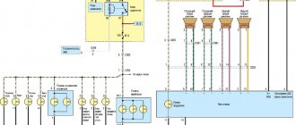
Electrical diagram of SeAZ-11116
On SeAZ-11116 cars with a Europanel and a Chinese 3-cylinder engine, the electrics have undergone changes. The cars use an electronic instrument cluster, which has led to the emergence of a number of new sensors. The fuel supply system was changed, into which a fuel pump with a control relay was introduced. Big innovations appeared in the engine compartment, where a fuel injection and ignition control system began to be installed. At the same time, the main part of the wiring, the fuse and relay box was carried over unchanged from the old carburetor version.
Electrical circuit SEAZ-11116 Part 1
Electrical circuit SEAZ-11116 Part 2
The diagram shows the following electrical equipment components:
| Number on the diagram | Element designation |
| 1/1 | High beam thread |
| 1/2 | Low beam thread |
| 2 | Front turn signal lamp |
| 1/4 | Side light |
| 3 | Side repeater |
| 5 | Generator and built-in relay regulator |
| 9 | Hall Sensor |
| 10 | Ignition coil |
| 12 | Starter |
| 13 | Spark plug |
| 14 | Klaxon |
| 17 | Coolant temperature sensor |
| 18 | Sensor for determining emergency oil pressure |
| 23 | Battery |
| 25 | Reversing signal switch |
| 26 | Device for turning on and off brake signals |
| 30 | Turn signal control relay |
| 31 | Parking Brake Warning Indicator Controller |
| 32 | Block for changing the operating mode of the windshield wiper |
| 33 | Additional heater motor resistor |
| 35 | Windshield wiper drive motor (front) |
| 37 | Heater fan motor |
| 38 | Radiator impeller drive |
| 39 | Cooling system motor control relay |
| 42/1 | Steering column turn signal switch |
| 42/2 | A similar element for headlight modes |
| 42/3 | Steering column for controlling the windshield wiper and washer |
| 42/4 | Steering wheel button for horn |
| 44 | Egnition lock |
| 46 | External lighting control (dimensions) |
| 48 | Alarm management |
| 49 | Switching heater fan speeds |
| 52 | Instrument cluster |
| 63 | Speed sensor |
| 74/1 | Cigarette lighter |
| 74/2 | Cigarette lighter socket illumination system |
| 75 | Fluid volume measuring sensor in the brake drive |
| 76 | Parking brake limit switch |
| 77 | Diagnostic connector |
| 81 | Portable lamp socket |
| 83 | Washer pump drive |
| 87 | Limit switch for interior lighting system (on the door) |
| 89 | Interior lighting |
| 93 | Sensor measuring fuel level (with backup indicator) |
| 98/1 | Rear light size |
| 98/2 | Turn signal located in the stern lights |
| 98/3 | Brake lamp |
| 98/4 | Reverse gear indicator |
| 99 | License plate light |
| 104 | Radiator Fan Thermal Switch |
| 108 | Rear fog light |
| 112 | Tail wiper motor |
| 113 | Rear window washer motor |
| 115 | Rear window heating filaments |
| 121 | Heated glass controller |
| 125 | Additional relay |
| 126 | High beam controller |
| 127 | Similar device for low beam |
| 129 | Starter controller |
| 133 | Heated rear window switch |
| 136 | Tail fog control |
| 137 | Rear window wipe control |
| 138 | Turning on the tailgate glass washer |
| 158 | Fuel injectors |
| 159 | Watch |
| 168 | Rear Fog Lamp Controller |
| 169 | Third brake light |
| 170 | Fuel pump controller |
| 171 | Fuel pump |
| 172 | Idle speed control system |
| 173 | Throttle valve angle sensor |
| 174 | Knock sensor |
| 175 | Canister purge system |
| 176 | Lambda probe |
| 177 | Absolute pressure sensor |
| 178 | Main relay |
| 221 | Engine control system controller |
Oka oil pressure sensor photo where it is located
I decided to install an oil pressure gauge. For what ? just . In theory, everything is simple - you need an adapter (tee) to install an oil pressure sensor, a pressure sensor and the indicator itself (I used both and the third from a VAZ-2106). I bought everything for about 250 rubles (2002). When installing the adapter in place of the emergency oil pressure sensor (2101-3810600), the oil filter flange broke off!! Although I pulled with a regular open-end wrench without any extensions! The flange is made of aluminum alloy and is quite fragile. The next day I had to go to Moscow and buy this filter flange (1111-1012024) and its gasket 1111-1012030. The next day (I did everything in the evening after work) I began installing the flange. When installing the flange, I broke the “6” key. (the flange is secured with two M8x30 screws with a 6-point hexagon socket) Having decided that I had tightened it enough, I filled it with oil and drove off without looking. After 5 km, all the oil leaked out and we had to go back in tow. The next day I bought oil (Luxoil Extra 0W40 - the cheapest of the liquid ones, since it was heading towards winter), a high-quality set of hex keys, and a sealant gasket. Spitting on the advice of car manufacturers who do not recommend installing oil system parts on sealant, I installed a flange with a paronite gasket on the sealant, applying sealant on both sides of the gasket, only trying to spread the sealant in a thin layer and letting it dry longer so as not to get into the oil system. I started installing the adapter. This also has its pitfalls. Firstly, the engine compartment of the OKI is cramped, and installing an adapter with pressure sensors (for the pointer and for the warning lamp) is inconvenient - the mudguard gets in the way. And secondly, the main thing, it seems to me, is that there is a danger of these sensors-adapters-fittings touching the mudguard when the power unit vibrates - on bumps, etc. It is impossible to position the sensor so that the sensor is pointing upward at OKE - the filter gets in the way. Place it so that the sensor is pointing down? There is a danger of them touching the ground. Consequences? - see above . Therefore, I removed the mudguard (right mudguard 1111-2802022), with difficulty unscrewing the rusty screws, and installed the tee so that the sensor axis is directed approximately horizontally. After this, in my opinion, there was much less dirt in the engine compartment. And only the next day (the sealant polymerizes for a day) I filled it with oil and was on wheels.
From the oil pressure indicator I removed the useless wiring harness from OKE and the backlight and emergency pressure lamps. I installed female type terminals on the wires suitable for the indicator and connected them directly to the oil pressure indicator according to the following photo:
What does the pressure indicator show? In the speed range from idle to 3000. 4000 - approximately 4 atm, the overpressure increases approximately in proportion to the engine speed up to the maximum (8 atm at a speed of 5000. 6000). The readings vary somewhat, obviously depending on the temperature, voltage in the on-board network, type of oil and etc. Over the two years since the installation of the oil pressure indicator, the oil pressure at idle has decreased slightly - from 4.4.5 atm to 3.5. 4 atm. Moreover, when changing the oil for the last time, I filled in a mixture of Luxoil extra oils 0W40 -1.5 liters and 5W50 - 1 liter. — no changes in the pressure indicator readings. November 19, 2004
December 13, 2006 Over the past 2 years, the oil pressure at idle has remained almost the same - 3.5. 4 atm, the maximum at high speeds decreased slightly to 6.7.5 atm. The oil I currently use is Yukos System 0W-40, there is practically no difference compared to the previous Luxoil.
Installation of an oil pressure gauge on the OCU Installation of an oil pressure sensor on the OCU Installation of a device indicating oil pressure on the OCU Installation of an oil pressure indicator from the VAZ-2103 on the OCU Installation of an additional engine oil pressure gauge in the OCU Installation of additional devices on the OCU
Fuse diagram for VAZ-1111 and 11113
The fuse block is located at the bottom of the instrument panel on the driver's side. The unit is protected on top by a quick-release plastic cover with a spring lock. The machine uses obsolete cylindrical type fuses. A list of inserts is printed on the outside of the lid.
Fuse markings on the cover
If a fog light is installed on a VAZ-1111 or 11113, it is protected by a separate insert (nominal 8A) located on the wiring harness next to the control button.
List of fuses with a description of the protected circuits on cars with a carburetor engine:
| Number on the diagram | Denomination, A | Protected elements |
| 1 | 16 |
|
| 2 | 8 |
|
| 3 | 8 | Left side high beam and indicator lamp in the instrument cluster. |
| 4 | 8 | Starboard main beam. |
| 5 | 8 | Low beam on the left side of the car. |
| 6 | 8 | Likewise on the right side |
| 7 | 8 | Side lights on the left side (front and rear), registration plate illumination and indicator for turning on the “dimensions” (in the instrument cluster) |
| 8 | 8 | Dimensions of the starboard side, lighting system for the cigarette lighter socket and instrument cluster |
| 9 | 16 | Operation of turn signal indicators in hazard warning mode, rear window heating filaments together with the control relay |
| 10 | 16 |
|
Next to the fuse block there is a frame with five relays for the following purposes:
- turning the fan motor on and off;
- low beam activation;
- selecting high beam operating modes;
- starter engine starting systems;
- threads of electric heating of the tailgate.
External view of the relay block on the Oka car
All relays used on VAZ/SEAZ 1111 and 11113 are of the same type, which simplifies vehicle repairs in the field.
Replacing the turn signal relay is demonstrated in a video filmed by Sergey Neverov.
Rain sensor DDA-07
The rain sensor is designed to improve comfort, reduce driver fatigue, increase safety, and increase the service life of windshield wipers and blades when driving in rain or wet road conditions. Suitable for domestic cars - Niva, Classic, Oka.
Rain sensor 722.3777-05 (replacement for DDA-07) replaces the windshield wiper relay for VAZ 2121 / 2131 Niva 4x4, VAZ - 2101-2107, 1111 Oka. The device also has a function for adjusting the pause of the wiper swings in the first position of the wiper lever.
List of cars with which this rain sensor works:
VAZ / Lada: -2101; -2102; -2103; -2104; -2105; -2106; -2107; -2121 / 2131 Niva 4×4; -1111 "Oka".
More details about the applicability of the sensor can be found here.
For models VAZ-2108, VAZ-2109, VAZ-2110, VAZ-2111, VAZ-2112, IZH-2126 (old fuse box), AZLK 2141 “Moskvich”, Chevrolet Niva, “UAZ-Patriot”, UAZ-3160 is used relay DDA-15.
For models VAZ-2108, VAZ-2109, IZH-2126 (new fuse block), VAZ-2113, VAZ-2114, VAZ-2115, Kalina, Priora, and some foreign cars, the DDA-25 relay is used.
Model DDA-35 is used on cars with a built-in electronic wiper relay (control signal - minus).
The DDA-45 model is used on the Lada Granta Lux car with a built-in electronic windshield wiper relay (control signal - plus) and other cars with a similar connection diagram.
The DDA-55 model is used on cars with both positive and negative connections. It has pause adjustment and other advanced functions. Recommended for foreign cars.
Model DDA-65 is similar to DDA-55, but additionally includes a light sensor.
Principle of operation:
The optical sensor is placed on the windshield of the car inside the passenger compartment, so that it is in the operating area of the windshield wiper blades. The DDA uses an infrared ray to check the condition of the glass itself. Depending on the presence of moisture or dirt, the level of the reflected signal will change. Based on this signal, the electronic unit will turn on the windshield wiper. Thus, as soon as water appears on the glass, the wipers turn on. The sensor takes into account the speed of the car (the higher the speed, the more often the wipers operate), as well as the intensity of the rain itself. In case of such an unpleasant phenomenon, when your car is splashed out of a puddle by another car, the sensor will see such a large volume of water already at a distance of 10 cm and turn on the windshield wiper in advance. At the same time, the driver can at any time independently turn on the wipers and adjust the frequency of sweeps with a standard switch.
Installation is very simple and does not require special skills or tools.
The operation of the DDA is not affected by factors such as glass fogging, the presence of fog, temperature, or time of day.
Suitable for all types of glass (tinted, athermal, isothermal), because The sensor automatically adjusts to the transparency of the glass.
Warranty - 1 year.
Option 1: By courier
The time and date of delivery will be confirmed by the manager after registration.
Delivery cost: 300 rub.
Common electrical faults
Common problems with electrical equipment on VAZ-1111 and 1113:
- Failure of external lighting devices. A common cause of failure is burnt out lamp filament; the unit must be replaced. If the light bulb is intact, then there may be a defect in the electrical wiring, due to which a short circuit occurs and the fuse fails. The fuse link is replaced with an identical one; it is prohibited to use parts designed for a higher current. It is also unacceptable to install homemade jumpers (“bugs”), as this can cause a fire. If a repeated burnout occurs, it is necessary to check the circuit and eliminate the wiring fault.
- Wire breaks occur at points where the insulation is subject to bending or friction against moving surfaces. An example of such a point is the junction of the door and the body. Damaged areas must be replaced with products made of similar material with an identical cross-section.
- Oxidation of contact surfaces due to moisture or aggressive liquids (for example, battery electrolyte). It is necessary to clean the surfaces down to metal, restoring the transmission of electric current.
- Relay failure associated with burnt contacts or coil breakage. The unit cannot be repaired; it must be replaced with a new one. In the event of a rapid re-failure, the vehicle's electrical system must be checked at a car service center.
- Sudden battery discharge is due to an internal short or current leakage. In winter, a partially charged battery may lose capacity due to low air temperatures. You need to charge the battery and check the condition of the wiring. If necessary, the power source must be replaced.
- Pulsating operation of external lighting lamps with an unusually bright glow indicates a breakdown of the relay regulator on the generator. Repair requires removing the unit and replacing failed components.
- Insufficient battery charge (the warning light does not go out when the engine is running). The cause may be wear on the brushes or commutator, or insufficient tension on the drive belt. The generator needs to be repaired, since the battery charge is enough for 150-200 km during the daytime.
- Poor contact between the ends of the cylindrical fuses and the spring-loaded elements in the mounting block. It arises due to the design features of the unit. Many owners, tired of dealing with the defect, install homemade blocks for knife inserts. Usually a short section from the GAZ-3110 is used, designed for 13 seats. There are self-assembled units designed for fuses and relays.
Photo gallery
The process of installing a new mounting block with blade elements.
Burnt contact of the standard unit
Destruction from local heating is clearly visible
Jumpers on the new block required to reduce the number of insertion locations
Wired unit
Maintenance, repair
Of all the car’s electrical appliances, only power supplies require maintenance:
- Battery (periodic recharging using chargers, monitoring the level and density of the electrolyte);
- Generator (periodic check of drive tension, replacement of worn graphite brushes).
It is also important to monitor the condition of the wire insulation and prevent it from being damaged to avoid a short circuit. Oxidation of contacts often occurs at the wiring junctions, which can lead to failure of electrical appliances. Most of the electrical network components are maintenance-free and must be replaced if they fail.
Such elements include light bulbs, small electric motors, switches, relays, fuses, sensors
Most of the electrical network components are maintenance-free and must be replaced if they fail. Such elements include light bulbs, small electric motors, switches, relays, fuses, and sensors.
In the starter, generator, electric. In the heater and cooling system fan motors, mechanical breakdowns may occur - wear of bearings, bushings, brushes. All these components are repairable and it is often possible to restore their functionality by disassembling, troubleshooting and installing new parts to replace worn ones.
Preventive measures
The main measures to ensure reliable operation of the electrics of Oka cars:
- At least once every six months, clean the outer part of the battery case and check the electrolyte level (on serviced models). At the same time, it is necessary to recharge the battery using a special device. If the vehicle is rarely used, it is recommended to disconnect the terminals.
- When carrying out repair work, you should monitor the position of the wires, avoiding damage to the insulating layer. Wires passing near moving elements must not come into contact with them under any circumstances.
- It is not recommended to turn on devices with high current consumption (audio system, high beam headlights, etc.) with the engine off. This will cause the battery to drain faster.
- Do not use homemade elements to repair electrical circuits. All used parts and assemblies must comply with the standards laid down by the designer when developing the car.
- It is recommended to carry spare fuses, relays and lamps with you. This will allow you to make minor repairs if necessary.
- When carrying out repair work that requires the use of welding, it is necessary to disconnect the harnesses from the battery and generator. On machines equipped with an injection engine, it is recommended to disconnect the connector from the control unit.
Differences between old and new PSUs
- There are no significant differences in functionality. Both blocks work equally efficiently. Another thing is that the modification of cylindrical type fuses is outdated and it is becoming more and more difficult to find components every day.
- Some creative motorists practice installing a power supply on Oka from Lada 10 - 15 models. Theoretically, such an upgrade is possible, but it will just require a lot of knowledge and experience in assembling electrical circuits.
- You need to re-solder the entire power supply, five relays - switches. Loop the parts onto one board and fix it to the frame under the dashboard. To ensure safe work, use the services of certified workshops and auto electricians.
- Remember that unprofessional intervention is more likely to harm than improve the efficiency of a particular unit.
- The average service life of an old-style power supply is 60 – 65 thousand km. The service life of blade type fuses is 80 – 90 thousand km. Depending on operating conditions, quality and professionalism of assembly, the interval can be increased to 5 - 10 thousand km.
- When purchasing parts, carefully check the catalog numbers with the data in the operating instructions for the technical device.