The Digitronic company has been operating in the LPG market for more than eight years. Its equipment is installed on many cars. Digitronic is not a monobrand; the equipment of this company includes elements from different manufacturers, including the Polish company STAG. The equipment of this brand has managed to establish itself well among car owners. On the Internet you can find many positive reviews about the products of this brand, despite the fact that its cost is slightly higher than the cost of equipment from other manufacturers. However, such an investment brings profit in the future. For example, with an annual mileage of 30-40 thousand km and fuel consumption of 10 liters per hundred, you can save about 40-60 thousand rubles.
Digitronic gas equipment systems belong to the 4th generation gas equipment. The products of this company can be installed on the Lada Granta. According to the manufacturer's statements, Digitronic equipment undergoes multi-stage quality testing. All components comply with the requirements of technical regulations. HBO elements are tested many times. The company's website contains the entire range of technical documentation, as well as all the necessary programs, thanks to which equipment can be configured and faults found. Digitronic gas equipment comes with a 12-month warranty.
What is needed for proper installation?
To properly install gas equipment on a car, you will need a certain set of equipment and tools:
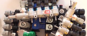
- HBO set 4;
- gas hoses with clamps 60-80cm long, Ø4-5mm and Ø12mm 50-100cm (for a 4-cylinder engine); 40-70cm vacuum tube Ø6mm; a cooling system hose with two metal tees corresponding to the size of the inlet/outlet on the gearbox - the length of all lines is selected individually for the car;
- thermoplastic gas tube of the required length (you can use copper or aluminum);
- auto tools;
- drill and/or screwdriver;
- drills (Ø4.8mm, crown 30mm);
- tap 6mm;
- electrical tape, heat shrink tube, hair dryer;
- soldering iron (materials for soldering wiring);
- multimeter;
- metal clamps/brackets with self-tapping screws (for fastening lines under the bottom);
- a can of anti-corrosion treatment or auto enamel;
- engine intake manifold gasket.
You will also need a lift/overpass or inspection hole.
Advantages and disadvantages of HBO Digitronic
Studying numerous reviews from owners of cars with 4th generation digitronic gas equipment, you can find both positive and negative sides.
Of the minuses, it is worth noting only complaints about the impossibility of self-adjustment, as well as premature failure of individual components of the system. But these disadvantages may be only partly true.
In practice, upon detailed analysis, it often turns out that the first and second statements are due to the incompetence of the technician who installed/configured the equipment. Also, untimely or low-quality maintenance of gas equipment or its absence at all.
However, do not forget about fake digital electronics. The advantages are obvious:
- a wide selection of trim levels for both budget small cars and premium cars.
- ease of self-installation, configuration, and maintenance. All instructions/manuals are available
- maintainability (spare parts/repair kits available)
- high quality of system parts and reliability of components (all components undergo multi-level testing)
- manufacturability, it is possible to diagnose and adjust equipment parameters directly from a smartphone through the original application.
How to connect all elements of the gas system?
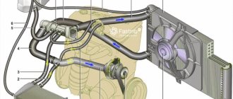
Each 4th generation LPG kit must contain a connection diagram for an injection car; the system is installed according to it. For different manufacturers it may differ slightly (for example, the electrical circuit), but the general installation principle for all types of gas equipment is the same.
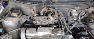
The installation process begins from the engine compartment. To begin with, it is advisable to protect the paintwork of the car by covering the lining and fenders with rag material. Remove the battery terminals.
Correct installation of gas injectors
In order to install HBO injectors, it is necessary to dismantle the intake manifold. You can, of course, not remove it, but then you are likely to encounter a number of difficulties:
- it is inconvenient to drill the manifold;
- violation of the correct/synchronous positioning of the nozzle nozzles (inserts);
- metal shavings getting into the engine cylinders.
If a plastic manifold is not so critical, then duralumin/aluminum, especially cast iron, is unacceptable to drill on the engine. This can lead to damage to the CPG (cylinder-piston group) or valves and their seats. The uniformity of gas supply depends on the correct location of the fittings.
So, after dismantling the manifold, as close as possible to the intake valves and the holes of the gasoline injectors, at the same angle (approximately 45˚), towards the center of the intake passage (along the air flow), we drill holes with a diameter of 4.8 mm. Also, to connect the vacuum, we make a hole in the manifold receiver, closer to the throttle valve.
Here it is important not to damage the walls of the wells of the standard injectors; also, mark and mark the drilling points in advance with a marker. Consider the possibility of reassembly so that the fittings do not interfere with the fastening of the manifold to the cylinder head.
Then, use an M6 tap to cut the thread and screw in each fitting using a hexagon or an appropriate wrench. Do not use excessive force; the brass inserts are easy to break off.
Some nozzles have tapered threads, so additional sealing is not worthwhile. But in some cases (for example, a hole has become loose) or for greater confidence, you can use a special sealing adhesive/thread locker.
We install the manifold in the reverse order, not forgetting to install a new gasket. Next, we screw the ramp with the injectors tightly to the engine, using a strip and dampers. We put on gas hoses/sleeves from the injectors to the fittings, securing them with clamps. There are four rules to consider here:
- the length of the hose should not be more than 15-20cm (the shorter the better);
- hoses must be cut to the same/equal length;
- do not exceed the nozzle angles recommended by the manufacturer;
- It is advisable to place the parts in an accessible place; hidden installation will complicate their maintenance.
Brief information about the brand
The products of the Polish company Digitronic are multi-brand gas equipment for any car. The key suppliers of components are such well-known companies as Stako, Valtek, Tomasetto, AC, AEB, EMER Palladio, Fagumit, whose production is located both in Europe and around the world.
Today, certified digital installation stations operate in sixteen regions of Russia. In addition, the company has a developed dealer network in all regions of the country.
The company is actively promoting its product, which has a positive effect on its promotion. Not counting retail customers, only the company’s wholesale customers are located in more than 200 cities of the Russian Federation and the CIS, whose number is about 1,300.
The main reasons why HBO Digitronic is in great demand among car enthusiasts and companies involved in the operation of vehicles:
- individual proposals for the selection of equipment;
- prompt technical support (online adjustment);
- personnel training (for equipment installation stations);
- providing a guarantee for work and equipment (with the possibility of extension);
- availability of a full range of spare parts in warehouses;
- fast delivery of spare parts;
- flexible pricing policy;
- high level of service.
In addition, due to the wide distribution of gas equipment of this brand throughout the world, the LPG market is flooded with counterfeits. “Chinese digitronic”, which has nothing to do with the original manufacturer, is especially common.
Differences between the original control unit and the fake
Therefore, the company has developed a number of measures to combat counterfeiting, one of which is to confirm the authenticity of products by registering them in its own system.
Instructions for connecting and programming the DGI Evo controller
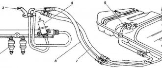
1. System connection 1.1. DGI connection diagram
Rice. 1 Wiring diagram on the car for DGI.
Rice. 2 Wiring diagram on the car for DGI Evo.
Rice. 3 Wiring diagram for a car equipped with a semi-sequential injection system
Rice.
4 Wiring diagram for a car equipped with a simultaneous injection system. 1.5. Installation method for the DGI, DGI Evo control unit. The DGI control unit must be installed with the wiring facing downwards. It is recommended to install the DGI Evo control unit with the wiring downwards. Regardless of the type of unit, it is recommended to install it in a place where it will not be exposed to high temperature and humidity. 1.6.
Selecting a gearbox Installation of the system should be carried out according to the connection diagram (Fig. 1).
When connecting DGI and DGI Evo sequential gas injection systems, you need to pay special attention to the correct choice of gearbox depending on the engine power and injector nozzles. If the gearbox is incorrectly selected in relation to the power of the car engine and the gas flow is high, that is, the throttle valve is completely open, the gearbox will not be able to provide the nominal pressure and the pressure in the system will begin to drop. If the gas pressure drops below the minimum value set on the controller, the system will switch to gasoline power. 1.7.
Selection of injector nozzles The choice of injector nozzle diameter also largely depends on engine power. The injectors must be selected in such a way that at high engine loads and high speeds the injection time conversion factor is close to unity. Most engines have an injection time of approximately 15 [ms]. The table below shows the diameter of the nozzles for the corresponding power values in one cylinder. To correctly calculate the nozzle diameter for a given engine, it is necessary to divide the vehicle power by the number of cylinders.
| Nozzle diameter [mm] Reducer pressure 1 [bar] | Power in 1 cylinder [kW] |
| 1,8-2 | 12 – 17 |
| 2,1-2,3 | 18 – 24 |
| 2,4-2,6 | 25 – 32 |
| 2,7-2,9 | 33 – 40 |
| 3,0 | 41 – 48 |
Please note that the data in the table is approximate and in some cases may differ from the actual data. This situation can occur, for example, in vehicles equipped with semi-sequential or simultaneous petrol injection. In this case, the nozzle diameters should be smaller than those indicated in the table, since with this type of injection control the amount of gas supplied is greater than for a full sequence - 2 times for semisequential (semisequential) and 4 times for full group. 2. Description of the diagnostic program Digitronic-DGI
2.1. Connecting the controller to the computer After correct installation, you need to connect the computer with the installed Digitronic-DGI diagnostic program to the DGI, DGI Evo controller using the RS interface from Digitronic. Before starting the program, turn on the ignition (to supply voltage to the controller); approximately 10 minutes after switching off, the unit automatically goes into sleep mode and communication with the computer cannot be established. After starting the program, if the serial COM port is selected correctly, a connection with the diagnostic program should be established, which will be confirmed by the “Connected” message in the lower left corner of the program window. The Parameters window is shown in Fig. 5.
Rice. 5 Parameters window
If the controller sends the message "Gas Controller Missing" and the message "No Communication" appears in the lower left corner, select a different port at the top of the screen from the Port menu.
2.2.
Version of the DIGITRONIС-DGI diagnostic program After starting the diagnostic program, you will see the program version at the top of the screen.
In Fig. 5 shows version 1.13.10.1. 2.3.
Main menu The main menu contains the following items:
Port – change the serial communication port, connection, disconnection with the controller Window – select the program window Language – select the language Controller update – update the controller program Documentation – Open the directory with available documentation Help – information about the program 2.4. Controller parameters
At the bottom of the screen, after the inscription “ver.”, the version number of the program installed in the controller is indicated (Fig. 5), where: 1.11 - PCB version number of the controller (necessary for upgrading the controller) 24 - Version number of the software installed in the controller 2007-03-22 09:24:45 — Date and hour of compilation of the version. A button is visible in the upper right corner.
Clicking this button causes a window with information about the controller to appear. A detailed description of the controller information window is presented in the further part of the instructions. In the parameters window there are a number of parameters that are individual for each machine. The Vehicle parameters group contains a choice: you need to set the Number of cylinders
- the number of cylinders in the car engine, from option 24 software in the controller, the following options are also available: - 1 cylinder (motor-bike) - 2 cylinders (motor-bike) We use this option for 1.2-cylinder engines, such as motorcycles
Number of cyl.
for 1 cat. – number of cylinders per ignition coil
RPM signal
– source of the RPM signal up to version 1.10 of controllers 12 V – rpm from the ignition coil, 5 V – rpm from the car computer From version 1.11 of controllers RPM detection threshold value in volts.
The detection threshold value should be selected so that the controller correctly reads the engine speed. Np. for pulses from a gasoline computer, which are usually at a level of 5 [V], we set the detection threshold to approximately 2.5 [V]. For pulses from the ignition coil, set the speed detection threshold to approximately 7 [V]. An exception is the Nissan Micra, in which the ignition pulses from the computer are at the level of 1.4 [V], in this case the speed detection threshold is set at the level of 1.0 [V]. In some Renault Megan models, the detection threshold should be set at 10 [V] Engine type
- engine type (Standard - naturally aspirated engine, Turbo - engine with turbine or compressor) Ex.
Gasoline Controlled “+” - Reading injection pulses in systems where the pulses are “positive”, i.e. The common signal for all injectors is ground, and the control pulses are up to 12 [V]. Lambda type
– Type of connected lambda probe: - voltage – standard voltage probe.
It is possible to connect 2 voltage probes. — UEGO ->
voltage – broadband probe UEGO (current).
The controller displays the values read by the probe on an oscilloscope in the same form as from the voltage probe. You can connect 1 broadband probe to the controller. — UEGO ->
Full range – wideband UEGO probe (current). The controller displays the values as voltage on the oscilloscope.
In this option you can monitor the full operating range of the UEGO probe, i.e. from lean to rich mixture. You can connect 1 broadband probe to the controller. You should not select the UEGO lambda options when voltage probes are connected, because this may damage them. See connection diagram!!! Injection type
- The type of injection system used in the car
is Standard
- Standard intermediate injection, gasoline injectors are controlled without current limitation.
— Renix
– Intermediate injection system, gasoline injectors are controlled with current limitation “Renix” In the group of gas controller settings we deal with the following groups of parameters:
Switching to gas
– parameters related to switching the controller from gasoline to gas.
Switching temperature
– the temperature of the gearbox, after reaching which switching to gas is possible.
Switching threshold
– engine speed, upon reaching which the controller will switch to gas.
For a rpm threshold <700, switching will occur at slow rpm. Switching time is the time from engine start to the moment when the controller can switch to gas. Cylinder switching
is the time between switching successive cylinders, when setting np 200[ms] with a 4-cylinder engine, switching from gasoline to gas or from gas to gasoline will last 4*200[ms].
For this option, it does not matter what kind of gasoline injection it is, that is, the so-called simultaneous one. Setting the switching time to 0 will result in switching from gas to petrol and vice versa, as well as switching off/on. electrovalves without delay. Switching to gasoline
- parameters related to switching the controller from gas to gasoline
Min. temp.
gas – minimum gas temperature, below which the controller switches to gasoline.
Min. LPG speed
– minimum speed on gas, below which the controller switches to gasoline.
Max.
rpm – maximum engine speed, after reaching which the controller switches to gasoline.
Error time given
.
– the time during which the gas pressure must be less than the minimum for the controller to switch to gasoline and report the error: “Gas pressure is too low.” Switch off at first
– with this option checked, the car will switch to petrol the first time the pressure drops below the minimum.
With this option checked, when the pressure drops, the controller switches some of the cylinders to gasoline to reduce gas consumption. Calibration parameters
– parameters related to controller calibration.
Pace. gas calibration – Gas temperature at which the controller was calibrated. Pressure - Operating - Gas pressure at which the controller was calibrated. You can change the operating pressure manually. However, every change in operating pressure requires correction of the coefficient map!!! Minimum - Pressure below which the switch to gasoline will occur if the pressure drop time is longer than the set pressure error time. Other parameters in the gas controller settings group: Fuel type - Type of fuel used in the gas installation Nozzle type - Type of gas used injectors. Changing the type of injector entails the need to re-carry out auto-calibration or correct the coefficient map!!! Gas inlet settings – Correction of individual gas injectors. Gas level indicator – Setting the switch LED thresholds. The button is used to enter the setting of the LED ignition thresholds on the switch and select the gas level indicator, which will be described below. After pressing the Gas Input Settings button. The gas injector adjustment window opens: After pressing the Gas injector settings button. The gas injector correction window opens: This window allows you to edit gas injectors as a percentage. Thanks to this option, you can adjust the gas mixture composition for individual cylinders. This amendment makes it possible to equalize possible differences in injection time between the parties, e.g. in engines in the “V” system. This correction must be entered as follows: After performing auto-calibration, check the gasoline injection time on individual cylinders when running on gasoline. By turning on individual gas injectors one at a time, you need to check for which cylinders there are differences in the gasoline injection time after switching to gas. It is necessary to select percentage corrections (of course, if this is required!) for individual injectors so that when individual injectors are switched on one at a time for gas, the gasoline injection time does not change. ATTENTION!!!
This option should be used as a last resort, that is, when the installation of the system is done correctly, all mechanical problems are eliminated, and there are still differences for individual injectors between the gasoline injection time when operating on gas. Only then can this option be applied. It is strictly prohibited, for example, to use wires of different lengths between the injector rail and the manifold for individual cylinders and to equalize the differences by corrections for individual injectors!!! The use of this option in a situation where some elements of the system are faulty or worn out during operation is also strictly prohibited. Using this option bypassing the instructions may result in damage to the machine!!! The corrections window can be opened regardless of the current tab, that is, we can have an open tab - e.g. map and at the same time an open correction (correction) window.
Removing data – removing data from the controller settings from a file Save – saving the controller settings to a file Factory – returning to the factory settings of the controller 2.5. Controller information
To open the Controller Information window, you need to click the button in the upper right corner of the program or select the “Controller Information” option in the help menu.
Figure 2 View of the Controller Information window
In the information about the controller window (Figure 2) the following parameters are visible: Controller operating time: Gasoline – the total operating time of the controller on gasoline, displayed in the form H – hours, M – minutes, S – seconds. From last connection – operating time on gasoline from the last connection with the computer. Gas — total time the controller operates on gas. From last connection – operating time on gas from the last connection to the computer. Inspection – Specified inspection time. When the operating time of the controller on gas exceeds the set inspection time, the controller will sound a sound signal each time after turning off the ignition, indicating the need for technical inspection of the installation. Canceling an installation inspection is described below. To set the installation inspection time, click the “Install” button in the program information window. After clicking the button, a window will appear (Figure 3):
Figure 3
View of the “Install inspection” window.
The required inspection time is calculated based on the selected mileage, after which the inspection must be carried out.
When calculating, the standard coefficient is 1 hour = 50 km, but it can be changed. In the window above, a mileage of 1000 km is selected, which is recalculated for the time of work, that is, in our case, 20 hours of work. To cancel the technical inspection, you must select “Disabled” in the selection field. If you select this option, the controller will not check the time until the inspection. Below the operating time in the “Controller Information” window, the events registered by the controller are presented: First connection.
PC – Date of the first connection between the controller and the diagnostic program.
First mod.set.
– First modification of settings in the controller.
If “???” signs appear instead of a specific date for these two events, this means that an error has occurred in the “information about the controller” section. Information about operating hours has been lost. The controller starts counting the time from the beginning. Mod date
1 – Mod. date.
5 – List of modifications to controller settings. From newest to oldest Unknown mod. mouth –The event will appear when a modification of the controller settings is performed with a date earlier than the date of the last modification performed. For each event there is also a “code” associated with the computer from which the settings were modified. Having the date of modification of the installation and the code of the computer from which the modification was carried out, you can check whether the controller settings have been modified by unauthorized persons. At the bottom of the window there is additional information: Controller S/N
– Serial number of the controller.
In earlier versions this option is not available. Your computer code is the code of the personal computer on which the Digitronic-DGI diagnostic program is currently running. 2.6.
Signals, injectors, switch On the right side of the program window (Błąd! Nie moŜna odnaleźć źródła odwołania.) there is a “signals” window and an injector window. In the “signals” window, the following signals are available that are measured by the controller: Gas pressure [bar] – the value of the gas pressure (pressure difference between the reducer and the suction manifold) MAP pressure [bar] – the value of the pressure in the suction manifold (absolute pressure value) Injection time [ ms] – petrol injection time – Petrol. 1 – Gasoline injection time for injector 1 – Gasoline. 2 – Gasoline injection time for injector 2 – Gasoline. 3 – Gasoline injection time for injector 3 – Gasoline. 4 – Gasoline injection time for injector 4 – Gasoline. 5 – Gasoline injection time for injector 5 – Gasoline. 6 – Gasoline injection time for injector 6 – Gasoline. 7 – Gasoline injection time for injector 7 – Gasoline. 8 – Gasoline injection time for injector 8 Injection time [ms] – gas injection time (for the first cylinder) Temperature Gas [°C] – gas temperature at the reducer outlet Temperature Ed. [°C] – temperature of the fluid in the gearbox Voltage lambda 1 [V] – voltage on the lambda probe 1 Voltage lambda 2 [V] – voltage on the lambda probe 2 Supply voltage [V] – voltage on the controller supply RPM [rpm] – engine speed All described signals are also visible on the oscilloscope. You can turn off this signal so that it is not visible on the oscilloscope. To do this, click on the value of this signal and mark it. By clicking on the name of this signal, you can change the color. Under the above described signals (Figure 5) there is a frame “Active gas”. This option is used to turn off individual gas injectors. Np. For a 134-cylinder engine, 4 gas injectors are normally active (green). To turn off a specific gas injector, you need to click on its image. This will turn it off and turn on the corresponding gasoline injector. Thanks to this option, you can diagnose mechanical damage to the injector. If you turn off the voltage, all gas injectors turn on. An LED switch is visible under the windows for signals and injectors.
Figure 4
LED switch type
There is a button on the switch to change the type of fuel. The diode next to the button informs about the operating mode of the controller: Off – the controller is running on petrol. On – the controller is running on gas. Flashing – the controller is in automatic mode. Information about the current fuel is displayed under the switch. At the top of the switch there are 5 diodes informing about the gas level in the cylinder. By clicking on one of the four LEDs, we enter the LED threshold setting
Figure 5
Setting LED Thresholds
In this window we set the voltages at which individual LEDs will light up.
We also select the type of gas level indicator. The gas level voltage is also displayed. When the “Set LED thresholds” window is highlighted, changing the gas level immediately changes the state of the LEDs. Serves to check the correct operation of the general reading sensor and the LED bar. When the window is closed (normal operation), the change in gas level on the sensor is shown in the LED line with a large delay 2.7. Autocalibration The Autocalibration window is designed to calibrate the engine at idle speed. When the engine is idling and the lambda probe is warm, press the auto calibration button. The air conditioning and headlights should be turned off, and the steering wheel should not be turned. During calibration, the controller will switch the system from gasoline to gas and back several times. When calibration is complete, the message Calibration Complete appears. During calibration, the following messages may appear: Engine speed: [rpm] too low – Engine speed is too low, check the “Number of cylinders per engine” setting
Connection diagram for 1st generation gas equipment to a carburetor
Equipment installation kit
This diagram shows what parts the 1st generation LPG consists of:
- Gas cylinder. Its capacity most often depends on the installation location. Installed outside the car or in the trunk, this eliminates gas leakage into the cabin.
- Multifunctional valve. Serves to control the filling and supply of liquefied gas.
- The ventilation device provides ventilation in case of leaks.
- High pressure liquid gas supply pipeline.
- Electric valve. Triggered to open the gas supply from the ignition switch
- Gasoline solenoid valve, the only function is to shut off the fuel supply when switching to gas.
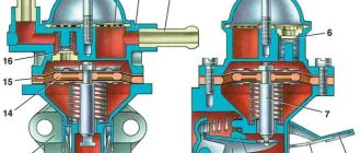
- Vacuum reducer HBO 1st generation. Converts from liquid to vapor and reduces fuel pressure.
- The mixer (mixer) mixes the gas with atmospheric air to form a fuel-air mixture.
- Dispenser. Serves to regulate the amount of gas supplied.
- Refill connector. Refueling at the gas station takes place through it.
Operating principle of 2nd generation gas equipment on an injector
2nd generation HBO is extremely common and popular in our country. Both because of the low price, affordable to almost every ordinary car owner, and because of the ease of operation, setup and adjustment. In any case, LPG is installed with the desire to save on gasoline, the prices of which are increasingly higher. The number of gas filling stations is increasing, and the level of service in installation and repair of gas equipment is getting better.
Before talking about the features of 2nd generation LPG on carburetors, we note important recommendations that must be followed if you want your car to work properly with such a combination - an injector and 2nd generation LPG:
- there should always be gasoline in the fuel tank;
- warm up in the cold season only on gasoline.
Digitronic gearboxes
For a gas cylinder system, the gearbox is one of the most important parts. Digitronic works with TOMASETTO gearboxes, which are designed for carburetor and injection engines and are part of the gas equipment starting from the second generation. Different models from this manufacturer differ in power and some variations in functions, such as preheating at the inlet or without an additional heating stage.