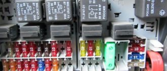
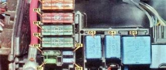
The relay and fuse box is also called the mounting block or black box. If a vehicle malfunction is detected related to electrical equipment, the fuses and relays are first checked. If a fuse is blown, you must first determine the cause of its blown before replacing it.
Where are the fuses for Lada Kalina 2?
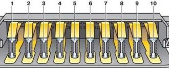
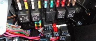
The fuse box is located near the driver's left foot. Pull the lower left corner of the cover (#1) to release the left locking point, then the middle (#2) and the two right locking points (#3 and 6). Then release the upper locking points (No. 4 and 5) and remove the cover.
Installing the fuse box cover is carried out in the following order: first snap the right fastening elements, then the lower ones, and then the upper ones. Make sure that the fastening elements of the cover are aligned exactly with the metal fasteners.
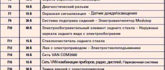
On the plastic cover of the mounting block there are symbols that indicate what each fuse (F) and relay (K) is responsible for, as well as their numbering.
labavto.com
The Lada Kalina has earned a reputation as a comfortable and reliable car. But, like all vehicles, it is not immune to various types of breakdowns. Quite often one or another electrical equipment fails. Some breakdowns are not critical, for example, the cigarette lighter does not work, but there are also those that can completely render your vehicle immobile.
This is, first of all, the failure of such an important component as the fuel pump. It is not always necessary to change the consumer in order to restore its functionality; very often it is enough to replace the fuse and the relay responsible for it to restore its functionality.
Car Lada Kalina
Let's say right away that on the Lada Kalina car the electrical circuits are protected by electrical fuses and relays located in several compartments. For example, the fuse for the cigarette lighter is located in the main compartment under the panel, and the fuel pump is located in the additional compartment.
All blocks with electrical fuses are installed in easily accessible and convenient places, so changing and checking protective elements will not cause difficulties even for a novice car enthusiast.
Fuse diagram Lada Kalina 2
The table shows a set of fuses for the maximum configuration of the “luxury” version (depending on the set of options, individual fuses from this set may not be used in the “Normal” configuration).
| Number and current* | “Standard” package | Equipment “Norma” and “Lux” |
| F1 (15A) | Ignition Coils, Injectors, Engine Control System Controller | |
| F2 (10/30A) | Daytime Running Lights | Power supply for the body electronics central unit, Driver's door module. |
| F3 (10/15A) | Alarm | Automatic transmission controller power supply, Automatic transmission control drive. |
| F4 (15A) | Airbag system controller | |
| F5 (7.5A) | Terminal 15 devices | |
| F6 (7.5A) | Reversing light | Reverse Light, Automatic Transmission Controller |
| F7 (7.5A) | Canister purge valve, mass air flow sensor/pressure sensor, DC | Canister purge valve, mass air flow sensor/pressure sensor, phase sensor, DC. |
| F8 (7.5A/-) | Direction indicators | Reserve |
| F9 (5A) | Side lights on the starboard side. | |
| F10 (5A) | Parking lights on the left side, Illumination of instruments and keys, License plate lights, Luggage and glove box lighting. | |
| F11 (5A) | Rear PTFs. | |
| F12 (10A) | Low beam and power supply for starboard electric corrector. | |
| F13 (10A) | Low beam and power supply for the left side electric corrector. | |
| F14 | Reserve | |
| F15 (10A) | Rear window washer, Rear window wiper | |
| F16 (-/5A) | Reserve | Driver door module |
| F17 | Reserve | Reserve |
| F18 | Reserve | Reserve |
| F19 (20A/-) | Door lock | Reserve |
| F20 | Reserve | |
| F21 (10A) | High beam, right headlight | |
| F22 (10A) | High beam, left headlight | |
| F23 (-/10A) | Reserve | Right fog lamp |
| F24 (-/10A) | Reserve | Left fog lamp |
| F25 (15A) | Heated front seats | |
| F26 (5A) | Anti-lock brake control unit | |
| F27 (15A) | Cigarette lighter | |
| F28 (15A) | Fuel pump | |
| F29 (20A) | Windshield washer | Windshield washer, Central body electronics unit |
| F30 | Reserve | |
| F31 (-/7.2A) | Reserve | Air conditioning compressor clutch, Automatic climate control system controller |
| F32 (7.5A) | Brake lights, Interior lighting | |
| F33 (25A) | Anti-lock brake control unit | |
| F34 (5A) | Instrument cluster, Diagnostic connector | |
| F35 (-/10A) | Reserve | Central body electronics unit |
| F36 (10A) | Sound signal | |
| F37 (10A) | Radio/Multimedia system | |
| F38 | Reserve | |
| F39 | Reserve | |
| F40 | Reserve | |
| F41 | Reserve | |
| F42 (30A/-) | Electric windows | Reserve |
| F43 (-/50A) | Reserve | AMT controller |
| F44 (30A) | Electric heater fan | Electric heater fan, Automatic climate control system controller |
| F45 (25A) | Heated rear window | |
| F46 | Reserve | |
* — the first value for the “standard” configuration, the second for “norm” and “luxury”.
Fuses located in the mounting block of the vehicle interior with the ERA-GLONASS function (in a variant):
| № | Current strength | Protected Circuits |
| F1 | 15A | Minimum speed radiator fan relay K18 (version with air conditioning or climate control) |
| Maximum speed radiator fan relay K4 | ||
| Air conditioning compressor clutch relay K10 (version with air conditioning or climate control) | ||
| Engine Control System Controller | ||
| Cylinder injectors | ||
| Ignition coils (for 16-valve internal combustion engines) | ||
| F2 | 7.5A | Intake pipe damper valve (for 16-valve internal combustion engine 21127) |
| Canister purge valve | ||
| Oxygen sensors | ||
| Phase sensor (for 16-valve internal combustion engine) | ||
| Mass air flow sensor (for 8-valve internal combustion engine or 16-valve internal combustion engine 21126) | ||
| AMT selector (version with AMT controller) | ||
| Tire pressure monitoring system control unit (terminal 30) (for EURO-6 vehicles) | ||
| F3 | 5A | Anti-Lock Brake Controller / Stability Control Controller |
| F4 | 15A | Airbag system control controller |
| F5 | 7.5A | Starter Relay K2/Automatic Transmission Controller |
| Unloading relay of ignition switch K1 | ||
| Rear window heating relay K6 | ||
| Seat heating relay K13 (optional) | ||
| Heated windshield relay K14 (optional) | ||
| Fuel pump relay K12 | ||
| Engine Control System Controller | ||
| Audio system | ||
| Electric Power Steering Controller | ||
| Wiper switch | ||
| Central body electronics unit (optional) | ||
| Terminal block "ERA-GLONASS" | ||
| Clutch pedal switch (for manual transmission) | ||
| Brake pedal switch | ||
| Instrument cluster | ||
| Door lock system control unit (optional) | ||
| Driver's door lock switch | ||
| Air conditioner switch (optional) | ||
| Automatic transmission speed sensor (optional) | ||
| Automatic transmission mode switch (optional) | ||
| AMT controller (optional) | ||
| Tire pressure monitoring system control unit (for EURO-6 vehicles) | ||
| F6 | 7.5A | Reversing light |
| Direction indicators | ||
| Parking system control unit (optional) | ||
| F7 | 10A | Starboard high beam |
| F8 | 10A | Left side high beam |
| F9 | 5A | Side lights on the starboard side |
| F10 | 5A | Left side marker lights |
| License plate lights | ||
| Trunk light | ||
| Illumination of instruments and keys | ||
| F11 | 5A | Rear fog lights |
| F12 | 10A | Starboard low beam |
| F13 | 10A | Left side low beam |
| Headlight electric adjustment control (optional) | ||
| F14 | 20A | Central body electronics unit: |
| (Windshield wiper) (optional) | ||
| Windshield washer | ||
| Windshield wiper | ||
| Steering column wiper switch | ||
| F15 | 10A | Rear window wiper |
| Rear window washer | ||
| F16 | RESERVE | |
| F17 | RESERVE | |
| F18 | RESERVE | |
| F19 | RESERVE | |
| F20 | RESERVE | |
| F21 | 15A | Fuel pump motor |
| F22 | 7.5A | Brake light switch |
| Brake lights | ||
| Additional brake signal | ||
| Anti-Lock Brake Controller/ Stability Control Controller | ||
| AMT controller (optional) | ||
| F23 | 5A | Instrument cluster |
| Diagnostic connector | ||
| F24 | 10A | Horn relay K8 |
| Sound signal | ||
| F25 | 15A | Socket for connecting additional consumers in the cabin |
| F26 | 5A | Terminal block "ERA-GLONASS" |
| F27 | 10A | Starboard fog lamp (optional) |
| F28 | 10A | Left side fog lamp (optional) |
| F29 | 15A | Heated front seats (optional) |
| F30 | 10A | Audio system |
| F31 | 10A | Central body electronics unit: (Direction indicators; Power supply for body electronics unit) (optional) |
| F32 | 30A | Central body electronics unit: (Power windows; Door and trunk locks; Rain sensor; Glove box light; Trunk light; Interior light unit; Daytime running lights) (in a variant) |
| F33 | 5A | Driver door module |
| F34 | 7.5A | Air conditioning compressor clutch (version with air conditioning or climate control) |
| Controller for automatic climate control system (optional) | ||
| F35 | 15A | Automatic transmission controller (optional) |
| Automatic transmission control drive (optional) | ||
| F36 | 15A | Alarm |
| F37 | 15A | Trunk lock actuator switch |
| Door lock control unit | ||
| 5A | Trunk lock actuator switch | |
| F38 | 10A | Daytime Running Lights |
| F39 | 15A | Cartridge for connecting additional consumers in the trunk |
| F40 | 10A | To the trailer lighting connector |
| F41 | 50A | Heated windshield (optional) |
| F42 | 30A | Heated exterior mirrors (optional) |
| Heated rear window | ||
| F43 | 50A | AMT controller (optional) |
| F44 | 30A | Electric heater fan |
| Controller for automatic climate control system (optional) | ||
| F45 | 30A | Power windows for front doors |
| F46 | RESERVE |
Relay diagram Lada Kalina 2
A set of relays is indicated for the maximum configuration of the “luxury” version (depending on the set of options, individual relays from this set may not be used in the “Normal” configuration).
| Number | Current* | “Standard” package | Equipment “Norma” and “Lux” |
| K1 | 50A | Unloading relay | |
| K2 | 30A | Additional starter relay | |
| K3 | 30/40A | Wiper relay | Radiator cooling fan relay |
| K4 | 30A | Radiator cooling fan relay | |
| K5 | 30A | Turn signal relay | A/C compressor clutch relay |
| K6 | 30A | Power window relay | Heated rear window relay |
| K7 | 20A | High beam relay | |
| K8 | 20A | Horn relay | |
| K9 | 20A | Low beam relay | |
| K10 | -/20A | Reserve | Reverse light relay (in versions with automatic transmission) |
| K11 | 20A | ECM main relay | |
| K12 | 20A | Fuel pump relay | |
| K13 | 20A | Seat heating relay | |
| K14 | 30/70A | Alarm relay | Heated windshield relay |
| K15 | 30A/- | Heated rear window relay | — |
| K16 | 30A/- | Additional alarm relay | — |
* — the first value for the “standard” configuration, the second for “norm” and “luxury”.
Relays located in the mounting block of the car interior with the ERA-GLONASS function (in a variant):
| # | Denomination | Relay purpose |
| K1 | 50A | Ignition switch unloading relay |
| K2 | 30A | Additional starter relay |
| K3 | 30A | Windshield wiper relay (optional) / Auto start relay |
| K4 | 30A | Maximum speed radiator fan relay (optional) |
| K5 | 30A | Turn and hazard warning relay (optional) |
| K6 | 30A | Heated rear window relay |
| K7 | 20A | High beam relay |
| K8 | 20A | Horn relay |
| K9 | 20A | Low beam relay |
| K10 | 20A | Air conditioning compressor clutch relay (version with air conditioning or climate control) |
| K11 | 20A | ECM main relay |
| K12 | 20A | Fuel pump relay |
| K13 | 20A | Seat heating relay (optional) |
| K14 | 70A | Heated windshield relay (optional) |
| K15 | 20A | Alarm relay |
| K16 | 30A | Hazard power relay/reverse light relay (optional) |
| K17 | 30A | Power window power relay/radiator fan relay in auto start mode |
| K18 | 30A | Minimum speed radiator fan relay (optional) |
Mounting block in the engine compartment
A set of fuses is indicated for the “luxury” version. In other versions, individual fuses from this set may not be used.
| Fuse no. | Current strength | Protected Circuits |
| FF1 | 50A | Heated windshield |
| FF2 | 60A | Generator |
| FF3 | 60A | Generator |
| FF4 | 40A (without air conditioning - 30A) | Electric radiator cooling fan |
| FF5 | 50A | Electromechanical power steering |
| FF6 | 40A | Anti-lock brake control unit |
Fuses located in the fuse box of the engine compartment of a car with the ERA-GLONASS function (in a variant):
| # | Denomination | Protected circuit |
| FF1 | 60A | Generator |
| FF2 | 60A | Generator |
| FF3 | 30A | Electric radiator cooling fan |
| 40A | Electric radiator cooling fan (version with air conditioning or climate control) | |
| FF4 | 40A | Anti-Lock Brake Controller / Stability Control Controller |
| FF5 | 25A | Anti-Lock Brake Controller / Stability Control Controller |
| FF6 | 50A | Electric Power Steering Controller |
Attention!
The relay and fuse diagram may differ depending on the configuration and production date of the vehicle. Current diagrams of the mounting block are presented in the operating manual for the date of manufacture of the car (download from the official website for a hatchback or station wagon).
Let us remind you that you will find other useful instructions in the section Repair and operation of Lada Kalina 2.
Keywords: mounting block Lada Kalina | Lada Kalina torpedo
2 0 0 0 0 0
Share on social networks:
Removal and replacement instructions
Replacing and identifying an unusable element in both the first and second blocks occurs in approximately the same way, so let’s consider the replacement process using the example of the one installed to the left of the dashboard.
Diagram on the back of the cover
Preparation
Be sure to remember that before you carry out work on electrical equipment, it doesn’t matter whether the cigarette lighter or the fuel pump has failed, the first thing you need to do is turn off the power to the system. To do this, turn off the engine and remove the negative terminal of the battery.
This video shows how you can quickly solve a problem with blown fuses on a Lada Kalina.
- We find the location of the block, it’s not difficult - the designers placed it on the left side of the dashboard under the cover.
- Open the lid.
- Using the diagram and table, we establish the location of the protective element we need.
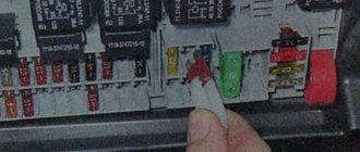
- The block contains tweezers, with the help of which we extract the required element.
- Let's examine it.
- We check with an ohmmeter or lamp.
- If the spiral is burnt out, install a new one of equal value.
- We connect the removed battery terminal.
- We start the car.
- Let's see whether our consumer has earned money or not.
- If everything is in order, then the work is finished. If the consumer does not work or the electrical fuse has blown again, then everything is more serious. It may be necessary to check the circuit or dismantle the consumer and check it.
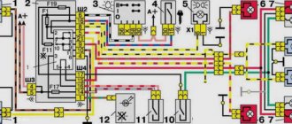
Layout of relays and electrical fuses
Explanation of the diagram shown in the photo.
The request returned an empty result.
Work with the block, which contains the element protecting the fuel pump and other elements responsible for the operation of the engine, is carried out in a similar way.
The request returned an empty result.
The protective element designed for 15 amperes, responsible for the fuel pump of the Lada Kalina, is designated F2 in the photo. To remove it, you need tweezers. All other work is carried out in the same way as in the large compartment.
Recommendations for use
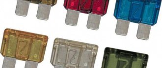
- If you are a responsible car owner, then be sure to carry with you a set of electrical fuses of various ratings. Perhaps they will help you out at some point.
- Under no circumstances should you install wires or bugs. This can lead not only to failure of the electrical consumer, but also to a fire.
- Replacement only with an element of the same value is acceptable.
- Before work, do not forget to turn off the power to the system.
Sorry, there are no surveys available at this time.
