Standard Lanos fuses from Chevrolet are located in three independent blocks. Each module is responsible for its own portion of wiring and equipment. In the CIS countries the car is produced under the Deo brand. The location of the main elements and the design of the car are no different. The first mounting block is located in the engine compartment and has a narrow purpose - protecting the main electrical equipment responsible for the operation of the power plant. The second unit, like that of Daewoo Lanos, is installed in the cabin under the driver’s feet. Only fuses are mounted here. The third part is located under the dashboard.
All structural parts have relays and fuses. Interchangeability of components is possible only if they are completely consistent.
Working principle of a car fuse
The components of automotive fuses are elements such as a body and a fuse link. Chevrolet and Daewoo Lanos vehicles are equipped with flag or plug-type devices. The body of such devices is made of plastic. The fuse link is located inside the housing, which does not necessarily have to be sealed. Two contacts (legs) protrude from the body, through which the part is installed in the electrical circuit of a certain device.
The most important parameter of a fuse is the amount of current it is designed for. All devices are designed to protect electrical wiring from fire, as well as prevent failure of electrical appliances. In simple terms, a fuse protects electrical equipment from short circuits and the flow of high current. High current can lead to melting and subsequent spontaneous combustion of the wiring.
The fuse link of the element is designed for a certain amount of current, which depends on the power of the pantograph (electrical equipment). As soon as the current in the circuit exceeds the rated value for which the fuse is designed, the fuse-link burns out. As a result, the circuit opens, thereby preventing melting of the wire insulation and failure of electrical appliances.
Once a fuse has tripped, it cannot be repaired and must be replaced with a similar current rating. It should be installed in place of the failed element only after the cause of the device’s operation has been identified. If, when replacing a failed fuse, you install a device with a lower or higher current strength, this will lead to the following situations:
- If the current is below the rated current, the device will trip when electrical appliances are turned on
- If the current is higher than the rated current, the fuse will not work, which will lead to melting of the insulation, as well as failure of the electrical appliance.
The rating of the protective element is indicated on the front side of the product. Additionally, manufacturers produce devices that vary in color. The color corresponds to the current strength for which the protective device is designed. Below is a table showing the device rating depending on color.
Using a table with colors is very convenient when the fuse rating is not visible. If you don’t know what rating a protective element should have in a circuit with a particular electrical appliance, then you shouldn’t guess. You can calculate it or use the information provided below.
There is no voltage supplied to the fuel pump
The fuel pump on Lanos, especially the original one, is not a cheap part, so before condemning it, you need to check the power circuits going to it. So, guess one: the pump is alive and well, the problem is in the power supply. Let's consider the classic sequence of checking the fuel pump for an open circuit.
Checking the fuel pump fuse - useful advice
Let's start with where the fuel pump fuse EF16 and relay K9 are located, which switches the power circuit from the battery to the fuel pump.
Now I will tell you one piece of advice that applies to all fuses in general, and which can save a lot of nerves and money in the future. And here's my advice - don't believe your eyes! If you have a spare fuse, then it is better to install it, and here's why: it happens that the fuse does not burn out , but simply cracks when you take out the fuse - visually it is intact and even rings, but when you insert it back, the legs move apart sides and contact disappears! If you have a multimeter, then you can ring the fuse without removing it from the block: on the sides of the fuse there is access to the terminals. My next piece of advice is to pay attention to the terminals and the plastic around them - poor contact may be between the terminal and the fuse leg. In my case, the fuse turned out to be intact, the next step is to check the fuel pump relay.
How to check the fuel pump relay
What can happen to the relay in principle, due to which it will stop switching the power circuit (from the battery): the contacts inside the relay may burn due to sparking, secondly: poor contact between the terminals and legs of the relay and the third thing that will need to be checked – voltage level on the control circuit (voltage that causes the relay contacts to attract). The picture above shows the principle of operation of the relay, the picture below shows the relay contact numbers and the electrical diagram.
The easiest way is to find the same relay in the relay block, for example, the radiator fan switching relay and swap it, while first inspecting the relay legs and terminals for carbon deposits, and also checking whether the seats for the terminals have melted. After you swap the relay, of course, you will need to check whether the fuel pump is working by turning the key in the ignition. If the result is negative, you need to measure the control voltage with a multimeter: remove the fuel pump relay, turn the ignition key and check the voltage between terminals 85 and 86. Automotive relays of this type operate at a voltage value of 7 V or more.
If you don’t have a multimeter, you can do it simpler: insert a jumper between power terminals 30 and 87, thereby eliminating the presence of a relay in principle. After this, sit in the passenger compartment and turn the key in the ignition. In my case, the fuel pump did not work.. Then I proceeded to the second stage of testing - to the fuel pump itself.
Where are the fuses on Chevrolet and Daewoo Lanos?
One of the main questions that all car owners ask is where the fuses are located. Before diagnosing the power circuit of a particular non-working electrical appliance, you should first find the required fuse. There are three places on Lanos where these devices are located. We will find out more about their location below.
Lanos have three fuse and relay blocks. Their locations are not known to all car owners, so we present information with photos:
- Block in the engine compartment. If you remove the cover of the unit, you will find the presence of not only protective devices, but also relays. This block is the main one, since this is where the devices responsible for protecting the ignition switch circuit are located
- Block in the cabin near the driver's feet. This block contains only fuses without relays. This block contains protective devices included in the circuit of interior electrical appliances - interior lighting, hazard warning lights, radio, ECU power supply, dimensions, etc.
- Relay box under the instrument panel. To gain access to it, you need to remove the decorative plug on the side of the dashboard or remove the panel of the headlight electric corrector unit. This unit is equipped with relay only
- An additional fuse is installed on the right side near the passenger's feet. It should be noted that this element was not installed on all Lanos cars, but only on those with an ABS anti-lock braking system. Its rating is 10A
- Additional relays are also installed under the hood of the car on the left side near the engine compartment
Knowing where the fuse and relay blocks are located on Chevrolet and Daewoo Lanos, you need to figure out which electrical appliances they are responsible for protecting and operating.
Checking the fuel pump directly
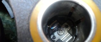
Having suffered a fair amount, it’s time to suffer even more... To gain access to the fuel pump cover, you need to “pull” the rear sofa: it is attached in two places to the floor (seen in the photo above), approximately in those places you need to pull. We removed the sofa - we unscrew the cover with a screwdriver and see the fuel pump connector (in the photo above on the right). To check the fuel pump directly , excluding all other elements of the car's electrical wiring, you need to apply voltage to the fuel pump directly from the battery. To do this, you first need to find which contacts in connector C901 are responsible for powering the fuel pump.
The picture above shows a connector (or, as people say, a chip) of a fuel pump (view from the pins). I didn’t remove the fuel pump from the gas tank, I just used a long wire to connect it to the battery. The fuel pump turned out to be alive!
Having experienced some bewilderment in connection with the diagnostic information received ( the pump is working, the fuse is working, the relay is working - all the obvious participants in the circuit are working! ), I decided to use a tester to check the voltage on the second half of the fuel pump connector (C901), coming from the bowels of the car. There was tension on him! That is, voltage was supplied to the fuel pump, the fuel pump was working, but did not work! How is this possible, you ask?
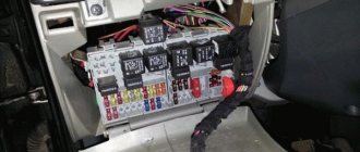
Fuse and relay box under the hood on Lanos
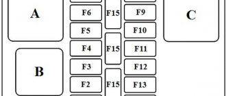
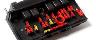
This block is located on the right side when you open the hood. It is closed with a plastic lid, which ensures tightness. The lid is secured with latches. Under it there are not only fuses, but also relays. For easy removal of fuses, there is a special plug. Below in the photo is the digital designation of devices, the decoding of which is in the table.
Fuse element F1 protects the power supply circuit of fuses F1-F7 and F15-F20. F12 - used on cars with air conditioning. Protects the electrical clutch circuit of the air conditioner. F15 is an air conditioning compressor clutch relay diode. F19 - protects the power supply circuit of the brake light, electric headlight adjustment, exterior lighting on the left side, corrector illumination, clock, rear fog lights, ashtray lamp, radio and air conditioner illumination. F20 - additionally protects the power supply circuit for the right headlight and license plate lights.
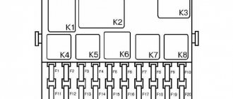
In the table above, relay R3 is used on Lanos cars with air conditioning. This relay is responsible for the operation of the electrical clutch of the air conditioning compressor. R4 - this element may also not be used if there is one fan on Lanos, Sens or Chance. He is responsible for turning it on. R5 - turns on the front fog lights if the car has them. R11 - relay for turning on the cooling fans at first and second speed.
Preparation
- If a fuse fails, then first of all we will determine in which block it is located. This is done quite simply. We look at its number in the decoding, then find its location on the diagram.
- If the electrical fuse is located in the engine compartment, you will need to remove the steam hose and open the cover. If the item we need is in the cabin, then just open the lid itself. These are all the differences between replacing a fuse in the engine compartment or in the passenger compartment.
- Then use tweezers to remove the faulty fuse. We examine it, trying to visually determine whether it is intact or burnt. It is better, of course, to do this work using a tester. Although it should be visually visible that the conductive part has burned out and in some cases the plastic shell itself may melt.
- Now we need to take a fuse of the same rating from the spare set and install it in place of the blown one.
- Replace the battery terminal. We start the car.
- We check the work of the consumer.
If the problem was the fuse, the equipment should work. If the fuse blows again, the problem is much more serious. The wiring needs to be inspected.
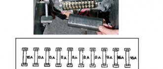
Fuse box in the car interior on the left under the trim
The interior fuse box of Lanos, Sens and Chance is responsible for protecting various electrical equipment. There are 20 fuses located on this block in the passenger compartment. Let's look at their purpose in detail.
The table below provides not only a description of the purpose of each element, but also the maximum current value. When searching for or replacing cabin fuses on a Lanos, you must rely on the data from the table.
Fuse F2 is responsible for turning off the rear PTF lamps. It also protects the power supply circuit for the headlight range control and the door open alarm. F5 - protects the power supply circuit of the vehicle's ECU. The power cable comes directly from the battery. Fuse F8 on the block is responsible for supplying power to the light alarm on the driver's door. Element F13 is responsible for the proper operation of the airbags. F15 - supply voltage to the coil or ignition module. F20 - battery for the electric heater motor for speeds 1-3.
Recommendations for use
- Every prudent driver must have a set with electrical fuses of different power, especially for those drivers who drive long distances. They cost pennies and can help out at some point.
- Sometimes, if some equipment fails and the electrical fuse is intact, simply move it slightly in the connector. Carbon or rust deposits could cause the chain to break.
- Replace only with a fuse of the same rating. If you put on a smaller one, it may immediately catch fire. Anything more and it won't be able to properly protect the equipment.
This video shows which fuse is responsible for the fuel pump. The cigarette lighter fuse is replaced in the same way.
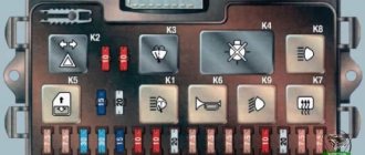
Relay block under the torpedo Lanos, Sens and Chance
Behind the control panel for the headlight range control of Lanos, Sens and Chance cars there are four relays responsible for the operation of the rear fog lights, direction indicators and hazard lights, heater fan and windshield wipers.
Under number “1” in the photo above there is a relay that is responsible for the operation of the electric heater motor, which is turned on at 4 speeds. If the stove stops working in position 4, then you need to check the serviceability of the relay. Number “2” is the device responsible for the operation of the car’s turn relay and hazard warning lights. Number “3” is the relay responsible for the operation of the windshield wiper, which operates in intermittent mode. Number “4” is the rear fog lamp relay on Lanos, Sense and Chance.
Separately, it should be noted that under the hood there are two more or one relay, which depends on the year of manufacture of the car. The devices are located on the left when the hood is opened near the engine shield. One element is responsible for sending a signal to start the engine, and the second is intended to control the operation of the generator. The relay supplies power to the generator integrated board.
This is interesting!
Short-circuiting relay contacts directly without using the device is strictly contraindicated. This will not only lead to the fuse tripping, but also the failure of electrical appliances.
What fuel pressure in the rail should be
Normal pressure is considered to be 2.5 atmospheres at idle. When gas is added, the pressure briefly increases to 3-3.2 atmospheres - this is a kind of imitation of an accelerator pump, like on a carburetor. These indicators are influenced by several factors:
- rail pressure regulator;
- fuel pump performance.
If the fuel pump does not provide the proper pressure, then there will be no pressure in the ramp. But within certain limits, the ECU will be able to compensate for this by increasing the injection time. But at low pressure, the accelerator pump imitation will not work, which will lead to failures.
A working fuel pump gives a pressure of about 5-7 atmospheres. But then how does 2.5-3 stay on the ramp? It's simple - the pressure regulator in the fuel rail is responsible for this. This is a small bypass valve, which is located on the rack, in the area of the fourth cylinder. Structurally, the pressure regulator is made in the form of a spring-loaded valve, which is also connected to a vacuum membrane.
You've probably seen that the rail pressure regulator is connected by a thin tube to the intake manifold. If it is disconnected from the manifold, it will maintain pressure due to the spring, and it will be equal to 3-3.2 atmospheres. And when the vacuum tube is connected, not only the spring, but also the membrane acts on the valve stem. Thus, the regulator has the ability to further adjust the fuel pressure in the rail due to changes in the vacuum in the manifold.
What is a relay and its purpose on a car
An element such as a relay on a Lanos, Sense and Chance car is designed to close and open electrical circuits. In simple terms, these devices supply power to powerful electrical appliances through small buttons.
If you do not use a relay, and, for example, start the engine directly, then the contacts in the ignition switch will immediately burn out or the button will melt. This is due to the fact that when starting the engine, the starter consumes a very large current, which, when passing through the ignition switch contacts, would melt them.
To avoid making the on and off buttons massive, relays are used in cars. These are a kind of protective devices that divide the circuit into high-voltage and low-voltage. The devices have a simple design, and their main element is a coil with a winding. When using a relay, it is important to understand the purpose of its contacts:
- 85 and 86 - coil contacts
- 30 - common, which is supplied with constant power from the battery
- 87 - normally open contact or power supply to the receiver
- 87a - normally closed contact, which is also called additional
When replacing a relay, it is important to pay attention to which element was previously in the socket - three, four or five-pin. Replace only with a device of similar design.
Procedure for checking an electrical relay
You can find out why the fuel pump stopped working by checking the circuits for ignition, including the relay. This is an electrical device that, when controlled by an electronic power source, supplies power to the pump motor, and when the contacts are opened, it interrupts this power. Its failure is often due to the failure of its coil or due to oxidation or burnt contacts that will need to be cleaned.
The Chevrolet Lanos fuel pump relay, where the control-controlled part (contact group) is located, as well as fuses, is located in the mounting block of the engine compartment - in the right front corner.
To check the status of the K9 relay, you will need devices such as a multimeter or test lamp, a probe and a piece of wire. However, if the fuel pump fails, it is first recommended to check the serviceability of fuses F17 and F16, specific to Chevrolet Lanos. How to test the fuel pump relay is a frequently asked question and the answer is quite simple - just use one of the methods below.
- First you need to remove the device from the mounting block and replace it with a working one, for example, relay K7 (for power windows). Activation of the fuel pump using the spare relay indicates a failed relay. If it does not turn on, check the power supply and control circuits of the electrical device.
- If there is no repairable spare relay, a similar way to check the functionality of the device is to install a jumper (a piece of wire, a paper clip) between contacts 30 and 87, which will close them when the ignition is turned on.
- You can determine whether the device needs to be replaced by measuring the voltage between pin 86 and ground (negative). When the ignition is on, it should be 12 V. We also check the voltage between pin 30 and ground. It is equal to the on-board network voltage. Its absence indicates a wire break between the contacts and ground. Otherwise, the sensor must be connected between pin 85 of the relay harness block and the positive terminal of the battery. If the indicator light does not light up when the ignition is turned on, this indicates a controller malfunction or a wire break. If the light comes on, it means the electrical device needs to be replaced.
- Also, using a tester in ohmmeter mode between pin 85 and the vehicle ground, you can measure the resistance, which, if the circuit is working, should be 1 Ohm.
Content
The steering mechanism is available with or without power assistance. The power-assisted version has a smaller gear ratio and therefore reacts more sharply to steering behavior.
The amplifier itself, depending on the speed of movement, operates with a variable gain. At high speeds, it practically turns off, and when parking and low speeds, it makes turning the steering wheel as easy as possible. The advantage of the steering mechanism is its layout.
Notes of Sanych
The steering rods are attached to the rotating arms of the telescopic struts not at the bottom, as in most front-wheel drive foreign cars, but at the top. This design allows you to avoid deformation of the steering rods when in contact with curbs and other road defects. To all of the above, you can add a high ground clearance of mm, which together ensures excellent adaptation of the car to domestic roads.
The safety of the driver and passengers is not ignored. To ensure this, the car is equipped with two airbags and an ABS anti-lock braking system. When developing Daewoo Lanos, designers paid increased attention to its reliability and durability.
This year, Lanos production in South Korea was curtailed. The project did not receive further development in Russia either - the financial crisis prevented it.
S, SE and SX. F15 15A - Ignition coil for Chevrolet Lanos. F16 15A - Direction indicator lamps in the headlights, direction indicator lamps in the rear lights, electric drive of the right outside rear view mirror. F17 15A - Power supply circuits for the engine control unit and fuel pump relay from the ignition switch. F18 20A - Electric motor for windshield wiper, electric motor for windshield washer pump. F19 10A - Coils of the rear window defogger relay, air conditioning compressor relay, power window relay, relays K4, K8, K11 of the electric motors of the cooling system fans.
F20 20A - Heater fan electric motor 1st, 2nd and 3rd speed. The fuse number is responsible for the cigarette lighter. Before you begin troubleshooting any electrical circuit, carefully study the corresponding diagram in order to understand its functional purpose as clearly as possible.
The scope of troubleshooting is usually narrowed by gradually identifying and eliminating normally functioning elements of the same circuit. Visually check the condition of all fuses, wiring and connectors on the circuit before proceeding with a more detailed check of the serviceability of its components. If you use diagnostic tools for troubleshooting, carefully plan, in accordance with the attached electrical diagrams, at which points in the circuit and in what sequence the device should be connected to most effectively identify the fault.
Daewoo Lanos alarm installation
The main diagnostic instruments include an electrical circuit tester or a voltmeter; you can also use a voltage test lamp with a set of connecting wires, an open circuit indicator probe, including a lamp, its own power source and a set of connecting wires.
They can be used to bypass and connect various elements of electrical equipment when diagnosing a circuit.
As already mentioned, before you start checking the circuit using diagnostic equipment, determine the location of its connection using the diagrams. One method of finding a short circuit is to remove the fuse and connect a test lamp or voltmeter instead.
There should be no voltage in the circuit.
- Maintenance of Chevrolet Captiva: regulations and cost - Tech
- Replacing brake fluid for Chevrolet Cobalt in Yekaterinburg
- Pump for Chevrolet Aveo T, buy, sell pumps with delivery at low prices
Removing and replacing the cigarette lighter
To complete the work, you will need a set of screwdrivers, a soldering iron with solder, a universal tester, and electrical tape. The cigarette lighter is replaced as follows:
- Open the hood. By disconnecting the battery terminals, the on-board network is de-energized. This will prevent short circuits when dismantling vehicle components. Remove fuse F19 from the mounting block.
- Pry up the center console by snapping off the plastic clips. First release the upper fastenings, then the lower ones. The metal parts of the latches must not fall into the console.
- Disconnect the wire blocks going to the radio. Remove the air conditioning cables. This step is skipped if you have climate control.
- Take out the center console along with the ashtray. Remove the three-pin connector. Remove the cigarette lighter unit.
- Install a new part and reassemble in reverse order.
DIY repair
If there is no contact between the plug and the cigarette lighter socket, clean the metal antennae with sandpaper. After this, they are given the correct position.
A more rare cause of failure is a violation of the integrity of the wires.
If the cigarette lighter does not work for this reason, replace the damaged cables.