Connection diagram 2110 carburetor
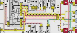
In front of the VAZ 2110 diagram
Rear diagram of VAZ 2110 carburetor
The diagram does not conventionally show that in the instrument panel wiring harness, the second ends of all wires of white, black, orange, white with a red stripe and yellow with a blue stripe are connected to each other at the same points.
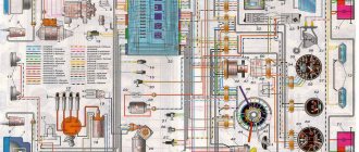
Complete diagram of VAZ 2110
| Position number on the diagram | Explanation of position |
| 1 | Headlights |
| 2 | front brake pad wear sensors |
| 3 | reverse light switch |
| 4 | VAZ 2110 fan motor activation sensor |
| 5 | engine cooling fan motor |
| 6 | sound signal |
| 7 | carburetor solenoid valve VAZ 2110 |
| 8 | carburetor limit switch |
| 9 | oil level sensor |
| 10 | oil pressure warning light sensor |
| 11 | coolant temperature gauge sensor |
| 12 | speed sensor VAZ 2110 |
| 13 | starter |
| 14 | VAZ 2110 battery |
| 15 | generator VAZ 2110 |
| 16 | windshield washer motor |
| 17 | washer fluid level sensor |
| 18 | coolant level sensor |
| 19 | windshield wiper motor |
| 20 | recirculation valve |
| 21 | micromotor gearbox for heater damper drive |
| 22 | heater motor |
| 23 | ignition coil VAZ 2110 |
| 24 | ignition distributor sensor |
| 25 | spark plug |
| 26 | switch vaz 2110 |
| 27 | carburetor electromagnetic valve control unit |
| 28 | additional resistor for heater motor |
| 29 | brake fluid level sensor |
| 30 | outdoor light switch |
| 31 | instrument cluster 2110 |
| 32 | fog light switch |
| 33 | fog light warning lamp |
| 34 | rear window heating indicator lamp |
| 35 | rear window defroster switch |
| 36 | Understeering's shifter |
| 37 | instrument light switch |
| 38 | ignition switch |
| 39 | mounting block VAZ 2110 |
| 40 | fuel level sensor |
| 41 | recirculation valve switch |
| 42 | socket for portable lamp |
| 43 | heater controller |
| 44 | on-board control system display unit |
| 45 | hazard switch |
| 46 | watch |
| 47 | heater control lamp |
| 48 | glove compartment lamp |
| 49 | side direction indicators |
| 50 | glove compartment light switch |
| 51 | Parking brake warning light switch |
| 52 | cigarette lighter |
| 53 | driver seat belt sensor VAZ 2110 |
| 54 | ashtray lamp |
| 55 | brake light switch |
| 56 | brake light switch |
| 57 | interior lamp for individual interior lighting |
| 58 | temperature sensor for heating system |
| 59 | switch in the front door pillars |
| 60 | switches in rear door pillars |
| 61 | exterior tail lights |
| 62 | interior tail lights |
| 63 | license plate lights |
| 64 | trunk light |
| K1 | lamp health monitoring relay |
| K2 | windshield wiper relay |
| K3 | relay-interrupter for direction indicators and emergency lights |
| K4 | low beam headlight relay |
| K5 | headlight high beam relay |
| K6 | additional relay |
| K7 | rear window heating relay |
| K8 | backup relay (not installed on vehicles of the VAZ 2110 family). |
| A | connectors for connecting the rear window washer motor |
| IN | to the warning light harness block |
| WITH | connector for connection to the on-board computer |
| D | to the headlight cleaner harness block |
| E | to the rear window heating element |
| F | block for connecting an additional brake signal |
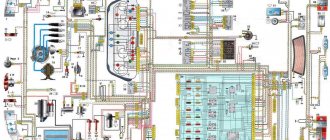
Diagram of the VAZ engine management system with BOSCH controller - ECM 21104 1.6 16V
1 – block of the ignition coil wiring harness to the ignition system harness; 2 – block of the ignition system harness to the ignition coil wiring harness; 3 – ignition coils; 4 – immobilizer warning sensor; 5 – immobilizer control unit; 6 – spark plugs; 7 – nozzles; 8 – diagnostic block; 9 – block of the ignition system harness to the ABS cabin group harness; 10 – controller; 11 – electric fuel pump; 12 – block of the ignition system harness to the fuel level sensor harness; 13 – fuel level sensor harness connector to the ignition system harness; 14 – block of the ignition system harness to the injector harness; 15 – injector harness block to the ignition system harness; 16 – block of the ignition system harness to the side door harness; 17 – speed sensor; 18 – idle speed regulator; 19 – throttle position sensor; 20 – coolant temperature sensor; 21 – mass air flow sensor; 22 – oil pressure warning lamp sensor; 23 – phase sensor; 24 – oxygen sensor; 25 – crankshaft position sensor; 26 — knock sensor; 27 – solenoid valve for purge of the adsorber; 28 – oil level sensor; 29 – coolant temperature indicator sensor; 30 – block of the ignition system harness to the instrument panel harness; 31 – instrument panel harness connector to the ignition system harness; 32 – ignition relay; 33 – ignition relay fuse; 34 – fuse for the electric fuel pump power supply circuit; 35 – electric fuel pump relay; 36 – electric fan relay; 37 – controller power supply fuse; 38 – ignition system harness block to the air conditioner connector; 39 – instrument cluster; 40 – ignition switch; 41 – electric fan of the cooling system; 42 – on-board control system unit; 43 – starter relay; 44 – contacts of the 8-terminal blocks of the instrument panel harness and the front harness; 45 – contacts of the 21-terminal blocks of the instrument panel harness and the rear harness; 46 – trip computer; 47 – diagnostic connector.
The QG16DE engine uses a phased distributed fuel injection system. This means that each cylinder uses its own fuel injector (port injection), and fuel injection is carried out by the injector only of the cylinder in which the intake valves are in the open position (phased injection). The amount of fuel injected varies depending on the duration of the electrical pulse supplied to the injector solenoid valve from the electronic engine control unit (ECU). In general, the electronic engine control system performs the following functions:
• control of the moment and duration of fuel injection; • control of energy accumulation time in ignition coils and regulation of ignition timing; • regulation and maintenance of engine idle speed; • electric fuel pump control; • control of electric radiator cooling fans; • control of the air conditioning compressor clutch; • control of the solenoid valve for purge of the adsorber of the gasoline vapor recovery system; • control of the “CHECK ENGINE” indicator lamp; • interaction with a standard car anti-theft system (ATS) or immobilizer; • generation of diagnostic trouble codes and interaction with an external diagnostic device; • generating signals for the trip computer; • integrated engine/automatic transmission control to reduce shock when changing gears by reducing engine torque; • emergency operation mode, which allows you to continue driving if individual components of the ECM fail.
The control unit performs these functions based on the results of processing the controlled parameters. These include:
• crankshaft position; • camshaft position; • throttle position; • position of the accelerator pedal • position of the parking-neutral handle of the automatic transmission; • position of the brake pedal (from the brake light switch); • air mass flow and its temperature; • coolant temperature; • on-board network voltage; • vehicle speed; • oxygen content in exhaust gases; • presence of detonation; • presence of a signal to turn on the air conditioner; • position of the key in the ignition switch; • APS (immobilizer) password for permission to start the engine; • refrigerant pressure; • pressure in the power steering.
The block diagram of the ECM (the devices included in it) is conventionally divided into 4 groups: electronic control unit (controller), sensors, actuators, auxiliary devices. Sometimes a car uses a non-contact ignition system - the block diagram is below:
- battery;
- Ignition breaker;
- Ignition breaker relay;
- Spark plugs VAZ;
- Electronic ignition module;
- Electronic controller;
- Sensor that fixes the crankshaft position;
- Setting disk.
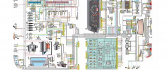
Electrical diagram 2110 injector 8 valves
The front part of the VAZ 2110 injector diagram
Rear half of the diagram
Complete diagram of VAZ-21102 injector (controller “January-4”)
| Position number on the diagram | Explanation of the position on the VAZ 2110 diagram |
| 1 | headlight |
| 2 | front brake pad wear meter |
| 3 | signal |
| 4 | cooling fan |
| 5 | rear light switch |
| 6 | electricity storage |
| 7 | generator vaz 2110 |
| 8 | oil pressure sensor |
| 9 | oil level sensor |
| 10 | spark plugs |
| 11 | sprayers |
| 12 | empty control |
| 13 | ecu terminal blocks |
| 14 | dpdz |
| 15 | dpkv 2110 |
| 16 | ignition module |
| 17 | antifreeze heat indicator sensor |
| 18 | starter |
| 19 | diagnostic block |
| 20 | dtozh |
| 21 | speed meter |
| 22 | petrol pump connection relay |
| 23, 35, 39 | circuit breakers |
| 24 | electric gasoline pump |
| 25 | micromotor reducer for heater damper |
| 26 | recirculation throttle |
| 27 | stove fan |
| 28 | windshield air pump |
| 29 | washer level meter |
| 30 | brake fluid level meter |
| 31 | antifreeze level meter |
| 32 | VAZ 2110 wiper gear motor |
| 33 | additional heater fan resistor |
| 34 | Relay for connecting the injection power system |
| 36 | canister purge throttle |
| 37 | dmrv |
| 38 | Cooling system fan connection relay |
| 40 | size switch |
| 41 | dd |
| 42 | lambda probe vaz 2110 |
| 42* | CO potentiometer (mounted on cars running on leaded gasoline. In this case, the lambda probe is not mounted) |
| 43 | fog light control |
| 44 | rear window heating control |
| 45 | fog light switch |
| 46 | rear window heating switch |
| 47 | dashboard vaz 2110 |
| 48 | relay and fuse block |
| 49 | gasoline level meter |
| 50 | ignition lock |
| 51 | instrument backlight brightness corrector |
| 52 | steering column switch |
| 53 | Illumination lamp for heater control levers |
| 54 | hazard warning light switch |
| 55 | VAZ 2110 heater ecu |
| 56 | recirculation throttle switch |
| 57 | ECU on-board control system VAZ 2110 |
| 58 | side direction indicators |
| 59 | heat meter for heating system |
| 60 | interior lamp |
| 61 | front interior light |
| 62 | carrying socket |
| 63 | VAZ 2110 watch |
| 64 | switches in the front door pillars |
| 65 | switches in rear door pillars |
| 66 | boardlight bulb |
| 67 | front light switch |
| 68 | cigarette lighter |
| 69 | ashtray light bulb |
| 70 | brake light switch |
| 71 | rear window defroster |
| 72 | exterior rear lights |
| 73 | interior rear lights |
| 74 | room light bulbs |
| 75 | trunk light bulb |
VAZ 2110 injector diagram
Electrical circuit for controlling the injection engine VAZ-21102, 2111, 21122 according to Russian toxicity standards (controller M1.5.4)
Injector diagram VAZ-21102, -21103, -2111, -21113, -2112, -21122 for Euro-2 toxicity standards (controllers M1.5.4N, “January 5.1”)
Electrical circuit of the VAZ-21102, -2111, -21122 injector for Euro-2 toxicity standards (MP7.0 controller)
Scheme of VAZ-2110 injector for Euro-2 toxicity standards (controller M7.9.7)
Wiring diagram of the VAZ-21114 engine injector of the VAZ 2110 car under Euro-3 toxicity standards (controller M7.9.7)
Diagram of a VAZ 2110 injector with a VAZ-21124 engine meeting Euro-2 toxicity standards (controller M7.9.7)
Electrical diagram of a VAZ 2110 injector with a VAZ-21124 engine meeting Euro-3 toxicity standards (controller M7.9.7)
Connection diagram 2110
Wiring diagram for connecting the starter VAZ 2110 model 57.3708 or 2110-3708010-02
| Position number on the starter connection diagram 57.3708 or 2110-3708010-02 | Explanation of position |
| 1 | electricity storage |
| 2 | generator |
| 3 | starter VAZ 2110 model 57.3708 or 2110-3708010-02 |
| 4 | ignition switch |
Wiring diagram for windshield wiper and washer
| Position number on the diagram | Explanation of position |
| 1 | windshield cleaner |
| 2 | windshield washer |
| 3 | windshield wiper and washer switch |
| 4 | mounting block VAZ 2110 |
| 5 | egnition lock |
| K2 | glass cleaner switch |
| K6 | Additional relyushka |
| A | Conventional numbering of plugs in the wiper motor blocks |
| IN | to sources of electricity |
Wiring diagram for connecting external lighting VAZ 2110
| Position number on the diagram | Explanation of the position on the external lighting diagram of the VAZ 2110 |
| 1 | lamp dimensions in the Faroah block |
| 2 | mounting block |
| 3 | size switch |
| 4 | ignition switch |
| 5 | Dimensions control on the dashboard |
| 6 | tail light bulbs |
| 7 | brake lamps |
| 8 | room lighting lamps |
| 9 | instrument lighting switch |
| 10 | brake lamp switch |
| 11 | VAZ 2110 on-board control system unit |
| K1 | relay for monitoring the health of lamps (contact jumpers are shown inside the relay, which must be installed in the absence of a relay) |
| A | to power supplies |
| IN | to instrument lighting lamps |
Electrical circuit for connecting an audio signal
| Position number on the diagram | Explanation of position |
| 1 | signal |
| 2 | signal switch |
| 3 | fuse box VAZ 2110 |
| A | terminal block for engine cooling fan |
| IN | to energy sources |
What is a fuel sensor
The fuel level sensor (FLS) is a control and measuring device that transmits information about the amount of fuel to the dashboard to the fuel level indicator (FLI), located on the dashboard next to the speedometer.
The operating principle of the FLS is simple: the fuel sensor is built into the gas tank system, consisting of a check valve, filter and fuel pump. A similar fuel supply and control system is used in injection engines. It is built into the gas tank cap and screws in with it.
This device is typical for diesel engines and is installed on the side as a separate unit. In this case, a float with a lever for tubular devices is placed inside the tank, and the movement of the latter determines the level of fuel in the tank.
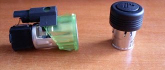
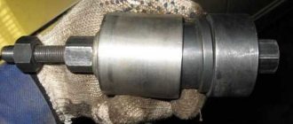
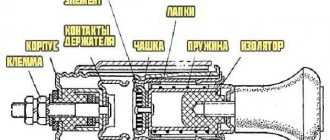
FLS device
In modern cars, LENs are installed mainly of lever and tubular types. In general, their operating principle has a lot in common, although upon closer examination some differences can be found between them. The VAZ 2110 is equipped with proven lever sensors. They are reliable, give a small error, but periodically fail. Sometimes their service life can be extended with simple manipulations, but sooner or later it becomes necessary to completely replace the VAZ 2110 fuel level sensor.
The figure shows a diagram of the VAZ 2110 fuel level sensor.
VAZ 2110 fuse circuit
Internal electrical connection diagram of the VAZ 2110 fuse box
Here is an electrical diagram of the internal connections of the fuse box of a VAZ 2110 . Connection lines for fuses and relays are marked on it. The symbols for these electrical safety devices are indicated. To better understand which relay protects what, a symbol of the electrical device being protected is marked next to it. The diagram shows plug connectors. The inner number indicates the terminal number on the plug, and the outer letter and number indicate the connector number.
Location diagrams of fuses and relays on different VAZ 2110 mounting blocks
This page presents three mounting blocks of fuses and relays for the VAZ 2110 car and its modifications. They all have their own designation. These blocks have different layouts of relays, spare fuses and auxiliary tweezers. These three mounting blocks are installed on different modifications of the VAZKH 2110 vehicle.
How to preserve a VAZ-2111 in winter
In order for the VAZ-2111 to serve for a long time, it is necessary not only to promptly eliminate faults related to the operation of the electrical circuit, but also to properly maintain the car. Experts give the following recommendations:
- Washing is good, but after cleaning the car it won’t be superfluous to treat the body parts with liquid wax. Why is this necessary? Wax fills even the smallest pores that appear in the paint, and dirt does not penetrate there, which means you can save money on another wash.
- If you are not satisfied with the roughness that a rag leaves after wiping off dirt, use polishing and rub the liquid glass. The latter will keep the VAZ-2111 in the best condition for at least 1.5 years.
- Many owners of domestic cars want to turn a boring vehicle into a real modern car. To do this, owners stick stickers on the surface, but no one takes into account that they are a real dust collector for small debris and dirt.
- Drive your car with care - service station workers assure that any scratch can be retouched by painting the part, but they do not specify that it is almost impossible to select an identical shade of paint previously used by the manufacturer. Therefore, the entire car has to be repainted.
- The headlights of the VAZ-2111 are made of plastic - this is how the designers take care of the recycling of raw materials. But plastic wears out over time and becomes cloudy. To extend the life of your headlights, initially protect the surface with armored film.
- There is an opinion that seat covers prevent abrasion of the seats themselves, but this is not the case. Moreover, it is easy to wash the seats; special products are used for this.
Replace your wipers promptly; they will protect the glass from scratches.
This free collection contains all the necessary documentation for the electrical equipment of the VAZ-2111 car - the circuit itself, the heating system, headlight cleaner, electronic engine control module and fuse box. The VAZ 2111 is the first station wagon in the line of front-wheel drive cars, which is a modernized concept of the rear-wheel drive VAZ 2104. In it, the wiring diagram for the injector and a number of other components have undergone changes as part of the concept change. Diagrams for other models can be viewed here.
VAZ 2110 wiring diagram
Wiring diagram for turns and hazard warning lights for VAZ 2110
| Position number on the diagram | Explanation of position |
| 1 | turn signal lamps in headlights |
| 2 | mounting block |
| 3 | ignition switch VAZ 2110 |
| 4 | hazard warning light switch |
| 5 | side turn signals |
| 6 | turn signal lamps in rear lights |
| 7 | turn switch |
| 8 | instrument cluster |
| K3 | turn signal and emergency flasher relay |
| A | to a source of electricity |
Electrical wiring diagram for connecting the trunk lock
| Position number on the wiring diagram for connecting the trunk lock | Explanation of position |
| 1 | fuse box VAZ 2110 |
| 2 | trunk lock switch |
| 3 | trunk lock motor |
| A | to sources of electricity |
| IN | numbering scheme for plugs in the gearmotor block |
Door lock system wiring diagram
| Position number on the diagram | Explanation of position |
| 1 | mounting block VAZ-2110 |
| 2 | fuse 8 A |
| 3 | ECU |
| 4 | Right front door locking motor |
| 5 | Right rear door locking motor |
| 6 | left rear door locking motor |
| 7 | left front door locking motor |
| A | to power supplies |
| IN | terminal numbering diagram in the control unit block |
| WITH | numbering scheme for plugs in locking gearmotor blocks |
Electrical wiring diagram for the rear window heating system
| Position number on the diagram | Explanation of position |
| 1 | connection block |
| 2 | ignition switch VAZ 2110 |
| 3 | rear window defroster switch |
| 4 | heating switch control |
| 5 | rear window defroster |
| K6 | additional relay |
| K7 | rear window heating relay |
| A | to sources of electricity |
Wiring diagram for the ignition system of a VAZ 2110 carburetor engine
This diagram was installed on VAZ 2110 with a VAZ-2110 carburetor engine, with a contactless ignition system.
| Position number on the diagram | Explanation of the position on the ignition system wiring diagram | Article number according to VAZ catalog |
| 1 | Nut M6 | 00001-0058962-11 |
| 2 | Washer 6 special | 00001-0011974-73 |
| 3 | Ring sealing | 21080-3706701-00 |
| 4 | Bunch of wires | 21080-3707080-10 |
| 5 | Spark plug | 21080-3707010-00 |
| 6 | Ignition coil wire | 21080-3707150-00 |
| 7 | Lock washer 6 | 00001-0026053-70 |
| 8 | Washer 6 | 00001-0026444-01 |
| 9 | Wiring harness | 21100-3724026-10 |
| 10 | Wiring harness | 21100-3724037-00 |
| 11 | Nut M5 | 00001-0058964-11 |
| 12 | Spring washer 5 | 00001-0011954-70 |
| 13 | Washer 5 | 00001-0005193-01 |
| 14 | Ignition coil | 21080-3705010-00 |
Wiring diagram for the ignition system of an injection engine with an ignition module
| Position number on the diagram | Explanation of the position on the ignition system diagram | VAZ catalog number |
| 1 | Fuel level sensor wiring harness | 21120-3724037-20 |
| 2 | Injector wiring harness | 21110-3724036-00 |
| 3 | Spark plug | 21110-3707010-00 |
| 4 | High voltage wiring harness | 21110-3707080-00 |
| 5 | Ignition system wiring harness | 21102-3724026-02 |
Wiring diagram for the ignition system of a 2112 injection engine with an ignition module
| Position number on the diagram | Explanation of the position on the VAZ 2110 ignition system diagram | VAZ catalog number |
| 1 | High voltage wiring harness | 21120-3707080-01 |
| 2 | Spark plug | 21120-3707010-00 |
| 3 | Injector wiring harness | 21120-3724036-00 |
| 4 | Fuel level sensor wiring harness | 21120-3724037-20 |
| 5 | Ignition system wiring harness | 21103-3724026-11 |
Wiring diagram for VAZ 2110 engine ignition system with individual ignition coils
| Position number on the diagram | Explanation of the position on the ignition system diagram | VAZ catalog number |
| 1 | Ignition coil wiring harness | 21104-3724148-00 |
| 2 | Spark plug | 21120-3707010-00 |
| 3 | Injector wiring harness | 21120-3724036-00 |
| 4 | Fuel level sensor wiring harness | 21120-3724037-40 |
| 5 | Ignition system wiring harness | 21104-3724026-00 |
| 6 | Additional wiring harness | 21102-3724100-10 |
How to replace a fuel level sensor with your own hands: step-by-step instructions
When the fuel sensor in a VAZ 2110 does not work, and all attempts to revive it have failed, all that remains is to replace it with a new one. You should not save on this device and delay the purchase of a new one. Moreover, its price is low, it is in the range of 350-500 rubles.
The FLS replacement is carried out from inside the car. To get to the gas tank, you have to remove the rear seat.
Important. When performing this work, you must follow safety rules. It is recommended to work with open doors.
The fact is that when replacing the sensor you will have to open the tank, and gasoline is a rather volatile and explosive chemical compound. The vapors of this hydrocarbon mixture can quickly fill the car interior. When working with a gas tank, you should never smoke or light matches to avoid a fire.
Now that you, dear reader, have been warned, you can proceed to replacing the faulty VAZ 2110 fuel level sensor with your own hands. The back seat was removed and the device was unscrewed from the gas tank. The new sensor is ready to be installed in place.
When buying a new device, you should pay attention to two points:
- When choosing a new sensor, it should be the same model as the old one. Pay attention to the numbers indicated on the body of the old device. Better yet, write them down for yourself and save them.
- Pay attention to the connector. When buying a new device, make sure that it is similar, since the number of ends on the connector for the FLS may vary: some models have three, while the FLS for injection engines has 4.
Before removing the old device, you must unclip the connectors holding the sensor.
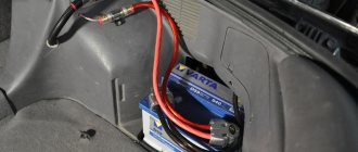
Access to the gas cap is located under the rear passenger seat. To get to it, you will have to remove the seat from the car. Then you should disconnect the pump by removing its chip. To relieve pressure, you need to start the engine. It will stall almost immediately, because without a pump no gasoline will flow to it. If the car has not been started during the day, then there is no need to start the engine. The pressure dropped on its own a long time ago. Resetting is necessary so that when the cap with the sensor is unscrewed, fuel does not spill out of the tank.
- 17mm wrench for unscrewing the fittings;
- Phillips screwdriver for removing the cover;
- Head 7 (for unscrewing the pump);
- After turning off the pump and releasing the pressure, unscrewing and removing the cover, you need to unscrew the fittings on the tank as shown in the picture.
Now you need to carefully remove the fuel pump. Remember that it is submersible, so it is drowned in gasoline. So you should remove it carefully, allowing the fuel to drain back into the tank.
Carefully set the pump aside, and then you can remove the float.
Assembly is performed in reverse order. Only instead of the old one, a new FLS is installed.
That's all! We hope our publication was useful to you and helped you cope with a faulty fuel level sensor on a VAZ 2110.
Source
Electrical cooling circuit for VAZ 2110
| Position number | Explanation of the position on the engine cooling diagram |
| 1 | fan motor |
| 2 | motor activation sensor |
| 3 | mounting block VAZ-2110 |
| A | to sources of electricity |
Wiring diagram of the VAZ 2110 generator model 94.3701
| Position number on the diagram | Explanation of the position on the connection diagram for the generator model 94.3701 |
| 1 | car battery |
| 2 | generator VAZ 2110 |
| 3 | mounting block |
| 4 | ignition switch |
| 5 | power supply charge control on the dashboard. |
Heater diagram 2110
| Position number | Explanation of the position on the VAZ 2110 heater diagram |
| 1 | fan motor |
| 2 | additional resistor |
| 3 | VAZ 2110 controller |
| 4 | assembly block |
| 5 | ignition switch |
| 6 | cabin air temperature meter |
| 7 | recirculation switch |
| 8 | recirculation valve |
| 9 | micromotor gearbox for heater damper drive |
| A | to the instrument lighting switch |
| IN | to sources of electricity |
Electrical diagram of the VAZ 2110 panel
| Position number on the diagram | Explanation of position |
| 1 | fuel reserve warning light |
| 2 | right turn signal lamp |
| 3 | right turn control |
| 4 | left turn indicator |
| 5 | TOZH index |
| 6 | external lighting signal light; |
| 7 | oil pressure warning light |
| 8 | parking brake control |
| 9 | battery charge indicator light |
| 10 | tachometer VAZ 2110 |
| 11 | "Check engine" warning lamp |
| 12 | speedometer vaz 2110 |
| 13 | brake fluid level warning light |
| 14 | alarm control |
| 15 | high beam warning lamp |
| 16 | fuel level indicator |
Signs of sensor malfunction: rules for self-diagnosis
The first and most obvious sign of a fuel sensor failure is a discrepancy between the readings of the fuel level indicator (fuel level indicator and the condition of the gas tank). True, another reason cannot be discounted: after all, the contact between the FLS and the control unit may well be broken or problems may arise in the dashboard. But this happens less frequently and is easily diagnosed.
The VAZ2110 fuel level sensor does not work correctly if the float is connected incorrectly or the float is installed incorrectly. If you correct the errors, the device will begin to give correct readings. But errors make themselves known immediately after an incorrect installation of the FLS, and if the device functioned correctly for a long time, and one day began to lie, it means that there are problems in its operation.
First, a visual inspection of the parts located outside is carried out. The presence of oxidation on connectors and terminals is detected immediately. If they are not significant, then the contacts are cleaned. The potentiometer can also be opened by prying off the cover with a thin screwdriver and inspecting the condition of the slider and resistive tracks.
Wiring diagram for connecting door power windows 2110
| Position number on the diagram | Explanation of position |
| 1 | mounting block |
| 2 | ignition switch VAZ 2110 |
| 3 | Right front door power window switch |
| 4 | Right rear door power window switch |
| 5 | Right front door power window motor |
| 6 | Right rear door electric window motor |
| 7 | left rear door power window motor |
| 8 | Left front door electric window motor |
| 9 | left rear door power window switch |
| 10 | left front door power window switch |
| 11 | power window switch |
| A | to power supplies |
| IN | to the instrument lighting switch |
| WITH | the order of conditional numbering of terminals in power window blocks |
Basic principles
Regardless of whether your VAZ 2110 has a carburetor or an injector, the basic principles for laying the wiring are the same. Finding a wiring diagram is not at all difficult, the main thing is to understand it. Actually, according to the location, the wiring is under the hood and in the cabin.
Its basic principles are the same, and boil down to the following:
- Whatever electrical device you have in a car, its connection will be single-wire. Moreover, the creators of the VAZ 2110 from the very beginning provided that both in the diagrams in the instruction manual and in reality, the colors of the wires would be clearly distributed. Simply put, all electrical equipment is connected using wires of a clearly defined color. Each unit has its own wiring harness enclosed in blocks. Naturally, this was done so that it would be easier for those who do the repairs themselves to understand this intricacy. Thus, replacing the wiring under the hood becomes more understandable. Advice: if you have a small problem with specific equipment and only one wire needs to be replaced, it is better not to be greedy and not change it to the first one you come across. Buy a complete harness and replace it with the wire of the desired color - it will be easier for you later;
- the wire supplying power to the positive terminal of the battery is always braided in red; it is also advisable not to change its color. In all diagrams it is designated as “P”, that is, plus;
- but the role of the “minus” (in other words, mass) is assigned to the automobile body;
- all terminals of any electrical consumers are directly connected to the body;
- Each system that is electrically connected has its own wiring harness.
Wiring diagram
In the VAZ 2110, if the battery is connected, all electrical equipment is energized. That is why, in fact, before starting any repair (especially if it is related to the electrical part of the car), it is strongly recommended to disconnect the battery.
Electrical diagram of VAZ 2110 headlights
Wiring diagram for headlights and fog lights
| Position number on the diagram | Explanation of position |
| 1 | block headlights |
| 2 | mounting block |
| 3 | headlight switch |
| 4 | size switch |
| 5 | fog light control |
| 6 | fog lamps in rear lights |
| 7 | fog light switch |
| 8 | Ignition switch VAZ 2110 |
| 9 | high beam headlight control on the instrument panel |
| K4 | headlight low beam switch |
| K5 | high beam connection switch |
| A | to sources of electricity |
| IN | terminal block for connecting headlights of another model |
Headlight adjustment diagram
Wiring diagram for fog lights
| Position number | Explanation of the position on the fog lamp connection diagram |
| 1 | fog lights |
| 2 | fog light connection stick |
| 3 | fuse box VAZ 2110 |
| 4 | switch size |
| 5 | fog light switch |
| A | to power supplies |
| IN | to the instrument lighting switch |
Electrical diagram for connecting headlight cleaners
| Position number | Explanation of the position on the headlight cleaner connection diagram |
| 1 | headlight cleaners |
| 2 | headlight washers |
| 3 | switch for headlight cleaners and washers |
| 4 | size switch |
| 5 | mounting block |
| 6 | ignition switch VAZ 2110 |
| 7 | connector for headlight cleaners and washers |
| A | to the instrument lighting switch |
| IN | to power supplies |
| WITH | numbering of plugs in headlight cleaner housings |
Tens ignition circuit
Ignition circuit for VAZ 2110 carburetor engine
| Position number on the VAZ 2110 diagram | Explanation of position |
| 1 | ignition coil |
| 2 | ignition distributor sensor |
| 3 | spark plugs |
| 4 | switch VAZ 2110 |
| 5 | ignition switch |
| A | to sources of electricity |
Wiring diagram of the ignition switch with the key inserted
| Position number on the diagram | Explanation of position |
| 15 | ignition system contact, generator excitation, headlights, turn signal, control devices, windshield and rear window wipers and washers and headlights, automatic heater control system |
| 30 | contact plus |
| 50 | starter terminal |
The KZ-881 ignition switch uses an LED instead of an incandescent lamp.
troubleshooting
The search for any wiring fault always starts with the contacts.
To check the condition of the contacts, it is necessary to carefully inspect the wires included in the system harness. This is done using different methods. Namely:
- Visual integrity check;
- Checking resistance with a device;
- Inspection of reliability, contact integrity, etc.
Pay special attention to high-voltage wires. They have a great responsibility to ensure the performance of all volatile equipment. But at the same time they are in a rather unfavorable environment. This is why a common cause of device failure is a wiring problem.
There are several main signs of a malfunction in high-voltage wires:
- When the radio is operating, noises are heard that were not there before;
- When driving, the car periodically jerks;
- Fuel consumption indicators increase;
- The engine begins to choke at low speeds;
- Exhaust toxicity increases significantly.
Prevention measures
If you notice or suspect that there are some problems with the electrical wiring, use a multimeter to check the high-voltage resistance. This is done as follows:
- The black wire is inserted into the left hole;
- The red wire is installed in the middle;
- The multimeter turns on to the blue twenty position;
- The probes are closed to each other;
- If the multimeter shows that the resistance is zero, then everything is fine with the high voltages;
- If the arrow points to 1, then the resistance is higher than normal. This indicates that the damaged wire must be replaced.
Useful multimeter
Golden rules
There are two basic rules associated with checking and replacing high-voltage wires of the electrical circuit of your VAZ 2110. Be sure to rely on them.
- Different wires may show different resistance. This is due to the difference in length. Therefore, take into account the tips from the instruction manual, which indicates the normal resistance values of a particular high-voltage device.
- There is always an aggressive environment under the hood, which can lead to failure of one of the high-voltage circuits. But if one wire produces increased resistance, everything still needs to be changed. Because over time, the others will also fail if one of them is already damaged.
Before attempting to change or repair the wiring yourself, be sure to disconnect the negative terminal from the battery. An incredibly important rule that should never be forgotten.