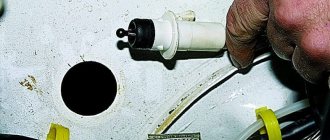
Disconnect the wiring from the pump. Using a Phillips screwdriver, remove the screws, and then remove the hatch cover located above the tank. The second ends of the orange wires are brought together to a point connected to plug “3” of the “X4” block of the mounting block. Their price is small, but their help and impact are significant. Wiring VAZ 2115. Part 2. “Check engine” warning lamp.
Table 7. For added safety, the model was supplemented with a brake signal and rear lighting. Thanks to different engines, the VAZ engine compartment wiring has its own design differences: the VAZ model has larger wiring harnesses due to the installation of additional sensors and electronic devices; The connectors of some electrical circuits have also changed; The layout of some of the wires has changed.
In addition, the layout of some of the electrical components as a whole was changed. On cars with an injection engine there is an additional unit located in the front passenger's feet.
When the lock socket illumination is on and the engine is running, the anti-theft locking device blocks the VAZ starter from re-engaging. The luggage compartment has become more spacious and convenient due to the increase in the trunk lid.
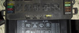
relays and fuses for the computer, Carlson and fuel pump
Varieties of VAZ 2115
| Automobile | Option code | Body type | Execution | engine's type | Toxicity standards | Dashboard | Controller | Note |
| VAZ-2115-01 | 10 —> 05.02 | sedan | norm | 21083-60 carburetor with contactless ignition system | R83 | 2114 | carburetor 21083-31 | basic equipment for the domestic market |
| 11 —> 03.02 | sedan | norm | 21083-53 carburetor with contactless ignition system | R83 | 21083 | carburetor 21083 | additional equipment for the domestic market with electric door locks and electric windows | |
| 13 —> 03.02 | sedan | norm | 21083-53 carburetor with contactless ignition system | R83 | 21083 | carburetor 21083 | additional equipment for the domestic market with electric windows | |
| 14 —> 03.02 | sedan | norm | 21083-60 carburetor with contactless ignition system | R83 | 2114 | carburetor 21083-31 | additional equipment for the domestic market | |
| 15 —> 03.02 | sedan | norm | 21083-53 carburetor with contactless ignition system | R83 | 21083 | carburetor 21083 | additional equipment for the domestic market without electric door locks and electric windows | |
| VAZ-2115-20 | 10 | sedan | standard | 2111-86 with distributed fuel injection | R83 | 2114 | 2111-1411020-70 2111-1411020-71 2111-1411020-72 | basic equipment for the domestic market |
| 11 | sedan | standard | 2111-86 with distributed fuel injection | R83 | 2114 | 2111-1411020-70 2111-1411020-71 2111-1411020-72 | optional equipment for the domestic market with heated seats | |
| 12 | sedan | standard | 2111-86 with distributed fuel injection | R83 | 2114 | 2111-1411020-70 2111-1411020-71 2111-1411020-72 | additional equipment for the domestic market without electric door locks and electric windows | |
| 13 | sedan | standard | 2111-86 with distributed fuel injection | R83 | 2114 | 2111-1411020-70 2111-1411020-71 2111-1411020-72 | additional equipment for the domestic market with heated seats without electric door locks and electric windows | |
| 110 | sedan | standard | 2111-86 with distributed fuel injection | Euro-2 | 2114 | 2111-1411020-70 2111-1411020-71 2111-1411020-72 | basic equipment for the foreign market | |
| 119 | sedan | standard | 2111-86 with distributed fuel injection | R83 | 2114 | 2111-1411020-70 2111-1411020-71 2111-1411020-72 | additional equipment for the foreign market without neutralizer and immobilizer | |
| 130 | sedan | standard | 2111-74 with distributed fuel injection | Euro-3 | 2114 | 2111-1411020-50 | additional equipment for the foreign market with phase sensor and rough road sensor | |
| VAZ-2115-21 | 10 | sedan | norm | 2111-86 with distributed fuel injection | R83 | 2114 | 2111-1411020-70 2111-1411020-71 2111-1411020-72 | basic equipment for the domestic market |
| 12 | sedan | norm | 2111-86 with distributed fuel injection | R83 | 2114 | 2111-1411020-70 2111-1411020-71 2111-1411020-72 | additional equipment for the domestic market | |
| 21 | sedan | norm | 2111-86 with distributed fuel injection | R83-02 | 2114 | 2111-1411020-60 2111-1411020-61 2111-1411020-62 | additional equipment for the domestic market with a neutralizer | |
| 110 05.02 | sedan | norm | 2111-86 with distributed fuel injection | Euro 2 | 2114 | 2111-1411020-40 | basic equipment for the foreign market | |
| VAZ-2115-22 | 10 | sedan | norm | 2111-86 with distributed fuel injection | R83-02 | 2114 | 2111-1411020-60 2111-1411020-61 2111-1411020-62 | basic equipment for the domestic market |
| 11 | sedan | luxury | 2111-86 with distributed fuel injection | R83-02 | 2114 | 2111-1411020-60 2111-1411020-61 2111-1411020-62 | additional equipment for the domestic market | |
| 110 | sedan | luxury | 2111-86 with distributed fuel injection | Euro 2 | 2114 | 2111-1411020-40 | basic equipment for the foreign market | |
| 119 | sedan | luxury | 2111-86 with distributed fuel injection | R-83 | 2114 | 2111-1411020-70 2111-1411020-71 2111-1411020-72 | additional equipment for the foreign market without neutralizer and immobilizer | |
| 130 | sedan | luxury | 2111-74 with distributed fuel injection | Euro 3 | 2114 | 2111-1411020-50 | additional equipment for the foreign market with phase sensor and rough road sensor |
Diagram of VAZ 2115 injector 8 valves
The front part of the electrical circuit VAZ 2115 injector 8 valves
| Position number on the diagram | Explanation of position |
| 1 | Headlights; |
| 2 | *Electric motor for headlight wipers |
| 3 | Fog lights |
| 4 | DTV VAZ 2115 |
| 5 | Signal |
| 6 | Engine compartment lamp switch |
| 7 | Motor cooling fan motor |
| 8 | Generator |
| 9 | Emergency oil level sensor |
| 10 | Antifreeze meter |
| 11 | Front brake pad wear gauge |
| 12 | **Window washer wire terminal block |
| 13 | Windshield washer nozzle pump |
| 14 | *Headlight washer pump |
| 15 | Rear window washer pump terminal block |
| 16 | Oil pressure alarm sensor |
| 17 | Engine compartment lamp |
| 18 | Terminal block for connecting to a bundle of wires of the VAZ 2115 engine control system of the VAZ 2111 model or to the sensor for connecting a fan with a VAZ 2115 engine of the VAZ 21083 model |
| 19 | Windshield wiper motor |
| 20 | Starter |
| 21 | Engine ignition system wiring harness terminal block |
| 22 | TOZH indicator sensor |
| 23 | Reversing light switch |
| 24 | Emergency brake fluid level meter |
| 25 | Battery |
| 26 | Emergency antifreeze level meter |
| 27 | Fog light switch |
| 28 | Fuse box VAZ 2115 |
| 29 | Brake light switch |
| 30 | Carrying cartridge |
| 31 | Headlight hydrocorrector scale light |
| 32 | Handbrake control switch |
| 33 | Terminal block for backlight bulb |
| 34 | Instrument lighting switch |
| 35 | Steering wheel switch |
| 36 | Emergency button |
| 37 | Front seat heater switch |
| 38 | Egnition lock |
| 39 | Rear fog light line fuse |
| 40 | Front seat heating line fuse |
| 41 | Door lock line fuse |
| 42 | Front ashtray light |
| 43 | Ignition switch |
| 44 | Cigarette lighter |
| 45 | Board light bulb |
| 46 | Front light switch |
| 47 | Heater fan electric motor |
| 48 | Additional heater motor resistance |
| 49 | Heater fan switch |
| 50 | Heater fan switch light |
| 51 | Heater control light |
| 52 | Electric windows of the front doors of VAZ 2115 |
| 53 | Right front door power window switch |
| 54 | Front door locking gear motor |
| 55 | Right front speaker wires |
| 56 | Rear door locking gear motor |
| 57 | Right rear speaker wires |
| 58 | ECU for blocking door locks of VAZ 2115 |
| 59 | Radio connection cables |
| 60 | *Headlight wiper switch |
| 61 | Rear window defroster switch |
| 62 | Rear fog light switch |
| 63 | Terminal block for connecting the right front seat heater |
| 64 | Rear fog light switch |
| 65 | Right front seat heater switch |
| 66 | *Fog switch |
| 67 | Dimensions switch |
| 68 | Left front seat heater switch |
| 69 | Terminal block for connecting the left front seat heater |
| 70 | Left front speaker connection wires |
Diagram of VAZ 2115 injector 8 valves rear part
| Position number on the diagram | Explanation of position |
| 71 | Left front door power window switch |
| 72 | Right front door power window switch |
| 73 | left rear speaker wires |
| 74 | side turn signals |
| 75 | switch on the front door pillars |
| 76 | switch on the rear door pillars |
| 77 | central interior light |
| 78 | front interior light |
| 79 | terminal block for connecting a gasoline pump |
| 80 | trunk light switch |
| 81 | instrument cluster VAZ 2115 |
| 82 | trunk light |
| 83 | signaling unit for on-board control system VAZ 2115 |
| 84 | minibus |
| 85 | terminal block for connecting the motor control system |
| 86 | rear exterior lights |
| 87 | rear interior lights |
| 88 | terminal block for connecting the rear window defroster |
| 89 | room lighting light |
| 90 | additional brake signal in the spoiler |
| Position number on the diagram | Explanation of position |
| A | headlights and headlight wipers |
| B | cigarette lighter |
| IN | mounting block, dashboard, ignition switch, windshield wipers, etc. VAZ 2115 |
| G | rear fog light switch |
| D | hazard warning button |
| E | gear motor for power windows and door locks |
| AND | central interior light |
In the twist of the instrument panel wires, the other ends of the white wires are soldered together and connected to the light switch of the instrument cluster (excluding the white wire from plug “4”, block “X2” of fuse box 28 to block 83 of the on-board control system indication). The other ends of the black wires are soldered at a point connected to ground. The other ends of the yellow wires with a blue stripe are soldered to a point and connected to plug 4 of block “X1” of the fuse box. The other ends of the white wires with a red stripe are connected to a point and connected to plug 10 of block “X4” of the fuse box. The other ends of the orange wires are soldered together and connected to plug 3 of the “X4” block of the fuse box.
- * - produced on parts of manufactured cars;
- ** - on vehicles of different configurations, one common pump and solenoid valves for headlight and windshield washing can be installed. Then the blocks 12 are connected to the washer pump, and the wires connected to the pumps 13 and 14 are connected to the corresponding solenoid valves.
Healthy ! VAZ 2114 diagrams.
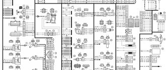
Summary electrical diagram of VAZ 2115 injector 8 valves
Modifications
The VAZ 2115 manufacturer offers consumers a choice of several configurations, on which their cost depends:
- One and a half liter carburetor engine. In this case, the car is marked as VAZ 2115-01.
- An engine with the same volume, characterized by the presence of a distributor fuel injection system. In addition, the car is also equipped with electronic control and is labeled as VAZ 2115-20.
Dimensions of the “fifteenth” Lada
Car electrical equipment
VAZ 2115 injectors or carburetors use a single-wire electrical circuit. In this case, the negative terminal of the power supplies is connected to the minus, and the positive terminal itself is supplied with a separate wire.
As a result of the fact that the VAZ 2115 carburetor and injector have certain differences, there is also a difference in the design features of the wiring:
- In injection versions, the wiring harnesses are slightly larger in size as a result of the fact that the system is equipped with additional regulators and other electrical equipment.
- As a result of the change in the circuit, changes were made to the design of some electrical circuits.
- In addition, the layout of some of the electrical components as a whole was changed.
Wiring diagram on the “fifteenth” Lada
On VAZ 2115 cars, as on its predecessors, the process of repairing the electrical wiring diagram and equipment usually leads to damage to the fixing clips. In any case, if these elements are damaged, they must be replaced, otherwise the electrical wiring may be very close to the hot motor, which will damage it.
Machine electrical protection
The electrical circuit, in particular, the power circuits in these car models are protected from various damages using fuses. The cost of these elements in stores is minimal, but they play a very important role and must always be in working order.
Fuses do not protect only:
- car battery charging diagram;
- ignition circuit;
- electrical circuit for powering the generator and starter.
Electrical equipment is protected by a block in which all fuses are collected, and this block is located in the engine compartment. Electrical equipment such as a starter, windshield wipers, as well as optics are connected to the general circuit via a relay. The relay is also installed in the block. In general, the electrical circuit of the wiper motor and optics is protected by bimetallic reusable elements.
Injector relay block
So, how is electrical equipment protected on domestic cars:
- fuses on the block, which are designed to protect various elements of equipment, are marked as F1-F20;
- K1 is a device that protects the optical cleaner circuit;
- K2 - is responsible for the functionality of the light alarm, as well as turn signals;
- K3 - the element ensures the functionality of the windshield wipers;
- K4 - the device protects the electrical circuit of optics, in particular, incandescent light bulbs;
- K5 - if the car is equipped with electric window regulators, then this relay is responsible for their performance;
- K6 - car steering horn;
- K7 — rear window heating system device;
- K8 - long-range vehicle lighting;
- K9 - low-beam vehicle lighting.
It should be noted that the lamps for the fog lights in the rear headlights are protected separately. For this purpose, a fuse is used, installed in the vehicle interior under the center console. It is located in the wiring harness, next to the optics power button.
Connection diagram for VAZ 2115 luxury version
The front part of the wiring diagram for the VAZ 2115 luxury version
| Position number on the diagram | Explanation of position |
| 1 | Flashlight |
| 2 | *fap wiper gear motor |
| 3 | fog lights; |
| 4 | DTV VAZ 2115 |
| 5 | signaling |
| 6 | engine light switch |
| 7 | engine cooling fan motor |
| 8 | generator |
| 9 | emergency oil level meter |
| 10 | antifreeze level meter |
| 11 | front brake pad wear gauge |
| 12 | **window washer pump terminals |
| 13 | windshield washer pump |
| 14 | *headlight washer pump VAZ-2115 |
| 15 | terminals for connecting the rear window washer pump |
| 16 | low oil pressure sensor |
| 17 | engine compartment light |
| 18 | terminal block for connecting to a bundle of wires of the engine control system |
| 19 | windshield wiper motor |
| 20 | starter VAZ 2115 |
| 21 | terminal block, connections to a bundle of wires of the ignition system on carburetor engines |
| 22 | antifreeze heat indicator meter |
| 23 | rear traffic light switch |
| 24 | brake fluid level indicator sensor |
| 25 | source of electricity |
| 26 | antifreeze level indicator meter |
| 27 | Relay for connecting front fog lights |
| 28 | fuse box VAZ 2115 |
| 29 | brake light switch |
| 30 | portable socket |
| 31 | hydrocorrector lighting bulb |
| 32 | handbrake connection signal light switch |
| 33 | terminal block for turning on the backlight bulb |
| 34 | instrument light switch |
| 35 | steering column switch |
| 36 | hazard warning light switch |
| 37 | Relay for the front seat heating element |
| 38 | ignition lock VAZ 2115 |
| 39 | rear fog lamp line fuse |
| 40 | front seat heating elements line fuse |
| 41 | door lock line fuse |
| 42 | front ashtray light bulb |
| 43 | ignition switch VAZ-2115 |
| 44 | cigarette lighter |
| 45 | glove compartment light bulb |
| 46 | glove compartment light switch; |
| 47 | heater fan motor |
| 48 | additional resistance of the stove motor |
| 49 | heater fan switch |
| 50 | heater switch light |
| 51 | heater control lamp |
| 52 | front door electric window motor |
| 53 | ESP switch of the right front door (located in the right door) |
| 54 | motor gearboxes for locking front door locks |
| 55 | wires for connecting to the right front speaker |
| 56 | motor gearboxes for rear door locks |
| 57 | wires for connecting to the right rear speaker |
| 58 | ECU for blocking door locks of VAZ 2115 |
| 59 | wires for connecting to the radio |
| 60 | headlight wiper switch |
| 61 | rear window heating element switch |
| 62 | connector for connecting rear fog lamps |
| 63 | terminal block for connection to the heating element of the right front seat |
| 64 | rear fog light switch |
| 65 | right front seat heating element switch |
| 66 | *fog light switch |
| 67 | headlight switch |
| 68 | left front seat heating element switch |
| 69 | terminal block for connection to the left front seat heating element |
| 70 | wires for connecting to the left front speaker |
Rear part of the wiring diagram for the VAZ 2115 luxury version
| Position number on the diagram | Explanation of position |
| 71 | left front door power window switch (located in the left door) |
| 72 | Right front door power window switch (located in the left door) |
| 73 | wires for connecting to the left rear speaker |
| 74 | side turn signals |
| 75 | light switches on the front door pillars |
| 76 | light switches on the rear door pillars |
| 77 | lamp |
| 78 | individual interior light lamp VAZ 2115 |
| 79 | terminal block for connecting to a bundle of electric fuel pump wires |
| 80 | trunk light switch |
| 81 | instrument panel VAZ 2115 |
| 82 | trunk light bulb |
| 83 | display unit for on-board control structure of VAZ 2115 |
| 84 | route ecu |
| 85 | terminal block for connecting a bunch of wires for motor control mode |
| 86 | rear exterior lights |
| 87 | rear interior lights |
| 88 | terminal blocks for connection to the rear window heating element |
| 89 | room lighting fixtures |
| 90 | additional brake light located on the spoiler |
| Method of numbering terminal blocks in blocks | |
| A | block headlights and headlight wipers; |
| B | cigarette lighter |
| IN | fuse box, instrument panel, ignition switch, windshield wiper and other electrical equipment components (terminal blocks with a different number of terminals have the same numbering method); |
| G | Rear fog light connector |
| D | emergency light switch |
| E | gear motor for power windows and gear motor for door locks |
| AND | interior light lamp |
* Mounted on some manufactured cars.
* On cars of different versions, 1 common washer pump and electromagnetic chokes for washing headlights and windshield can be installed. Then terminal blocks 12 are connected to the washer pump, and the wires connected to pumps 13, 14 are connected to the corresponding electromagnetic chokes.
In the bundle of instrument panel wires, the other ends of the white wires are soldered into one point, which is connected to the instrument lighting switch (except for the white wire, from terminal block “4” of block “X2” of fuse box 28 to block 83 of the on-board control system display). The other ends of the black wires are also soldered to the points connected to the body. The other ends of the yellow wires with a blue stripe are connected to the point attached to plug “4” of block “X1” of the fuse box. The other ends of the white wires with a red stripe are connected at the point connected to the “10” plug of the “X4” block of the fuse box. The other ends of the orange wires are connected at the point connected to plug “3” of block “X4” of the fuse box.
Integrated connection diagram for VAZ 2115 luxury version
Removal instructions
If you don’t know how to remove the window lifter handle, don’t despair, it’s easy to do. Before removing the mechanism, you need to remove the trim from the door. Then be sure to disconnect the wire block and the power window connector. Then remove the three nuts that secure the mechanism to the door. Next are two bolts that secure the lift and the glass itself.
Dismantling process
Then, lift the glass to the very top and fix it, you can use a screwdriver or ask someone to hold it. But it’s better to pull it out, because otherwise there is a risk that the glass may break.
To completely remove the mechanism, you need to additionally remove the door handle. To do this, unscrew its two screws and push the handle inside the door. Then, you will need to disconnect the rubber holder that holds the rod on the handle. Once you're done with this, you can pull out the handle, and then the window regulator itself through the same hole. Now you know how to remove the window handle and the entire mechanism.
Engine diagram VAZ 2115 injector
Here is a diagram of a VAZ 2115 engine with an injector of the VAZ 2111 model with a volume of 1.5 liters. This is an electrical diagram of a VAZ 2115 8 valve engine.
| Position number on the diagram | Explanation of position |
| 1 | spark plug 4 pots |
| 2 | spark plug 3 cylinders |
| 3 | candle for igniting the second pot |
| 4 | spark plug cylinder 1 |
| 5 | ignition module VAZ 2115 |
| 6 | diagnostic connector block |
| 7 | 1 pot sprayer |
| 8 | second pot sprayer |
| 9 | injector 3 cylinders |
| 10 | 4 pot nozzle |
| 11 | ECU VAZ 2115 |
| 12 | fuel pump connection relay |
| 13 | to the electric engine radiator fan |
| 14 | connector for connecting the engine radiator electric fan |
| 15 | main switch of the engine control system |
| 16 | DMRV VAZ 2115 |
| 17 | dpdz |
| 18 | dtozh |
| 19 | idle air control |
| 20 | canister purge throttle |
| 21 | dpkv |
| 22 | dd |
| 23 | oxygen sensor |
| 24 | to the ignition switch |
| 25 | ECU immobilizer VAZ 2115 |
| 26 | immobilizer sensor with indicator |
| 27 | car speed meter; |
| 28 | additional terminal connector |
| 29 | to the battery positive |
| 30 | terminal block for connecting to the car's electrical network |
| 31 | fuel pump |
| 32 | to control the fuel reserve (on the instrument panel) |
| 33 | to the gasoline level indicator |
| F1 | fuse for ECU and engine control system lines |
| F2 | ECU fuse |
| F3 | fuel pump line fuse |
On cars of the last years of production, changes were added to the engine control system: a DPRV, an ignition coil and a diagnostic connector block with digital pin numbering were installed (similar to the engine control system 11183). The rating of fuses FI and F2 has been changed to 7.5 A.
How to connect a button?
The driver and passenger door buttons are connected to each other, as well as to the ESP motor and power cable. Correct pinout of the power window button:
- Pin 1 on the driver's door is connected to pin 6 on the passenger side. Contact 1 on the passenger door is connected to the negative terminal of the ESP motor.
- Pin 2 on both buttons is connected to power.
- Pin 3 is the ground on the driver's side and the positive wire on the passenger's side.
- Contact 4 in both cases goes to the headlight switch.
- Contact 5 is ground in all cases.
- The positive wire of the ESP motor corresponds to pin 7 of the passenger door button.
Engine control circuit 11183 l.6 liter VAZ 2115
Here is an electrical circuit for controlling a 1.6-liter model 11183 injection engine installed on VAZ 2115 cars.
| Position number on the diagram | Explanation of position |
| 1 | Spark plug 4 pots |
| 2 | spark plug cylinder 3 |
| 3 | spark plug 2 pots |
| 4 | 1 pot spark plug |
| 5 | Ignition solenoid |
| 6 | diagnostic connector |
| 7 | 1 cylinder sprayer |
| 8 | nozzle 2 pots |
| 9 | sprayer 3 cylinders; |
| 10 | fourth cylinder injector |
| 11 | VAZ 2115 controller |
| 12 | Gasoline pump connection connector |
| 13 | to the engine electric fan |
| 14 | motor fan connection connector; |
| 15 | main motor control switch |
| 16 | dmrv |
| 17 | dpdz |
| 18 | dtozh |
| 19 | empty control |
| 20 | canister purge throttle |
| 21 | dpkv |
| 22 | knock sensor |
| 23 | oxygen concentration meter |
| 24 | to the ignition switch |
| 25 | ECU immobilizer VAZ 2115 |
| 26 | immobilizer sensor with warning light |
| 27 | car speed meter |
| 28 | additional terminal block |
| 29 | to the battery positive; |
| 30 | dprv |
| 31 | terminal block for connecting to the car's electrical network |
| 32 | gasoline pump |
| F1 | fuse for ECU and engine control system lines |
| F2 | ECU fuse |
| F3 | fuel pump circuit fuse |
Operating principle
A fan is a device that allows you to increase the efficiency of a cooling radiator. The radiator takes heat from the engine and releases it into the air. This process is accelerated by blowing through the blades of an electric fan.
The coolant flows through a closed, sealed system. Its task is to remove excess heat from overheated engine parts. Hot antifreeze flows into the radiator, is cooled here and returns back. While in the radiator, the coolant passes through a system of thin tubes. The incoming air flow while the car is moving helps to quickly remove excess heat from the engine compartment.
But when the car is stuck in traffic or idling, the air flow stops cooling it. In this case, the cooling system may not cope with its task. An electric radiator fan is designed to create air flow artificially. The temperature for turning on the fan on a VAZ 2114 is 85 degrees Celsius.
Local electrical circuits of VAZ 2115
Cooling diagram for VAZ 2115
High-quality color diagram of the cooling system of the engine 2111 of the VAZ 2115. It shows the cooling diagram of the VAZ 2115 injector 8 valves. Dual-circuit cooling system with thermostat. The cooling system is liquid, closed type, with forced circulation.
| Position number on the diagram | Explanation of position |
| 1 | Expansion tank |
| 2 | cork |
| 3 | vapor pipe |
| 4 | tube connecting the thermostat and expansion tank |
| 5 | dtozh VAZ 2115 |
| 6 | air damper assembly |
| 7 | radiator inlet pipe |
| 8 | coolant outlet pipe |
| 9 | left radiator tank |
| 10 | right radiator tank |
| 11 | drain plug; |
| 12 | heat exchanger core |
| 13 | fan diffuser; |
| 14 | fan blades |
| 15 | electric motor |
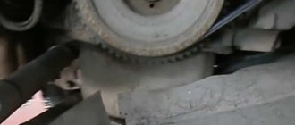
| 16 | pump toothed pulley |
| 17 | pump impeller |
| 18 | timing belt |
| 19 | stove outlet pipe; |
| 20 | pump supply hose |
| 21 | valve |
| 22 | stove heat exchanger |
| 23 | antifreeze drain pipe from the throttle pipe |
| 24 | tube supplying antifreeze to the throttle pipe |
| 25 | antifreeze temperature indicator sensor |
| 26 | outlet hose |
| 27 | heater supply hose |
| 28 | thermostat VAZ 2115 |
| 29 | antifreeze level meter |
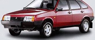
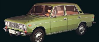
Differences from its predecessor
The VAZ 2115 car is a more modernized version of model 21099. The improvement of the “ninety-nine” contributed to the updating of the electrical wiring diagram.
It should be noted that, unlike 21099, the VAZ 2115 injector is equipped with newer body parts, in particular, we are talking about:
- improved shape of the front wings;
- the appearance of the headlights;
- back panel shape;
- different shape of the hood and luggage compartment.
Toy models VAZ 21099 and VAZ 2115
Of course, the changes also affected the engine compartment. Compared to 21099, the VAZ 2115 is equipped with a more powerful engine. Changes also affected the interior - a more advanced center console, instrument panel, and seats. An on-board computer was also added to the design of the car. Accordingly, the overall dimensions of the VAZ 2115 also underwent changes. But in general, this car remained the same - a front-wheel drive, five-door and five-seater sedan.
Schemes VAZ-2115-01
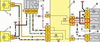
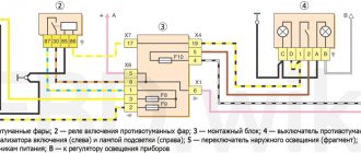
Electrical diagram for connecting the VAZ-2115-01 generator model 37.3701
| Position number on the diagram | Explanation of position |
| 1 | battery |
| 2 | generator VAZ-2115-01 model 37.3701 |
| 3 | relay and fuse box |
| 4 | battery charge control located on the instrument panel |
| 5 | ignition switch |
Generator voltage regulator test circuit
| Position number on the voltage regulator diagram | Explanation of position |
| 1 | battery |
| 2 | regulator ground output |
| 3 | generator voltage regulator 37.3701 VAZ-2115 |
| 4 | terminal "Ш" |
| 5 | terminal "B" |
| 6 | control 1 - 3 W 12 volts |
When 12V voltage is applied to terminals “B” and ground, the light bulb should light up. When a voltage of 15-16V is applied to terminals “B” and ground, the light bulb should not light up. If the light bulb lights up in two cases, then there is a breakdown in the regulator. If it does not light up, there are two options: there is a break in the regulator or there is no contact between the brushes and the terminals of the regulator.
Starter connection diagram 29.3708 VAZ-2115-01
| Position number on the starter diagram 29.3708 | Explanation of position |
| 1 | starter 29.3708 VAZ-2115-01 |
| 2 | battery |
| 3 | generator |
| 4 | fuse box |
| 5 | ignition switch |
| P1 | pull-in coil of traction relay |
| P2 | traction relay holding coil |
Scheme of the contactless ignition system VAZ-2115-01
| Position number on the diagram | Explanation of position |
| 1 | spark plugs |
| 2 | distributor sensor |
| 3 | ignition coil |
| 4 | switch VAZ 2115 |
| 5 | carburetor solenoid valve control unit |
| 6 | carburetor solenoid valve |
| 7 | carburetor limit switch |
| 8 | Ignition lock VAZ 2115 |
| 9 | fuse box |
| 10 | speed meter VAZ 2115 |
| 11 | motor blower fan motor |
| 12 | sensor for turning on the engine blower fan |
| A | terminal blocks for connecting to the front bundle of wires |
| B | terminal numbering diagram in the ignition sensor-distributor and speed meter blocks |
| IN | to voltage sources |
| G | to the instrument panel (impulse for tachometer) |
| E | to the instrument cluster (impulse for speedometer) |
Complete set of the contactless ignition system VAZ-2115-01:
- sensor-distributor - 40.3706, 40.3706-01
- switch - 3620.3734, 76.3734, RT1903, PZE4022
- ignition coil - 27.3705, 27.3705-01, 027.3705, ATE-1721, 8352.12, 3122.3705
- spark plugs - A17DVRM, A17DVRM1
- ignition switch - 2110-3704005, KZ-881
Diagram for checking the removed sensor-distributor
| Position number on the diagram | Explanation of position |
| 1 | distributor sensor VAZ 2115-01 |
| 2 | resistance 2 kOhm |
| 3 | voltmeter with a scale of at least 15V and an internal resistance of at least 100 kOhm |
| 4 | terminal connector of the sensor-distributor |
Switch test circuit
| Position number on the diagram | Explanation of position |
| 1 | arrester |
| 2 | ignition coil |
| 3 | switch VAZ 2115 |
| 4 | resistor 0.01 Ohm ÷ 1% not less than 20 W |
| A | to the square pulse generator |
| IN | to the oscilloscope |
Scheme for checking the distributor sensor on a VAZ 2115-01 car
| Position number on the diagram | Explanation of position |
| 1 | distributor sensor |
| 2 | adapter connector with a voltmeter with a scale of at least 15V and an internal resistance of at least 100 kOhm |
| 3 | distributor sensor VAZ 2115-01 |
Rear light diagrams for VAZ 2115-01
| Position number on the diagram | Explanation of position |
| 1 | turn signal lamps |
| 2 | size bulbs |
| 3 | brake lights |
| 4 | fog light bulbs |
| 5 | reverse light bulbs |
Electrical wiring system maintenance
To ensure the functionality of the electrical system, it is necessary to regularly check and diagnose the components:
- If problems are detected in operation (even minimal malfunctions), the condition of the connecting plugs should be analyzed.
- Often, after the owner moves the pad, contact is restored. Further use of such elements is not recommended.
- The unit needs to be replaced with a similar one, while simultaneously finding out the cause of oxidation of the old parts.
Relay contacts are prone to burning when exposed to high current. The devices can be removed from the unit and the condition of the conductive contacts can be inspected.
This requires:
- Remove the plastic protective cover.
- Carefully clean the burnt contacts with fine sandpaper and blow with air.
If there is significant wear on parts, it is necessary to install new relays.
Due to the location of the installation box in the air supply channel, it becomes clogged with dust and is exposed to moisture. Over time, this leads to the destruction of the conductive paths on the printed circuit boards and loss of contact. The unit should be inspected once a year; if defects are found, it is recommended to replace it with a new one. At the same time, it is necessary to monitor the condition of the grounding wire, which can oxidize at the connection points.
For correct operation of consumers, it is necessary to check the condition of voltage sources. The battery should be periodically recharged from a stationary device. Charging the battery and the functioning of the electrical circuit while driving depends on the tension and condition of the generator rotor drive belt. When the commutator and brushes wear out, the operation of the generator is disrupted, which leads to the car losing power.
Additional diagrams of the VAZ 2115 car
Fuse diagram for VAZ 2115 model 2114-3722.010
Here is an electrical diagram of the internal connections of the mounting block of fuses and relays of the VAZ 2114-3722.010 brand. It shows relays connecting the main consumers of electricity. These relays are presented with their own internal electrical circuits, providing the opportunity for a better understanding of the operation of this device. This diagram shows plug blocks on both sides with their numbers and the numbers of the terminal connectors. Internal number - indicates the number of the terminal connector. The external designation in the form “Ш1”, “Ш2” and so on is the designation of plug connectors.
Close the starter from the pushrod
Before starting the car directly through the starter, you should find out why the starter failed.
If the reason is a malfunction of the relay, solenoid relay, or starter winding, then you can start it from the pusher.
For this you will need a couple of assistants. They will rest against the trunk of the car and accelerate it, and you turn on the ignition key and first gear. The faster the assistants push the car, the faster it will start.
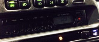
Did you know?
Acceleration from a pusher is the most popular method of starting a car without a starter among car enthusiasts.