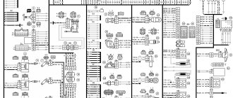
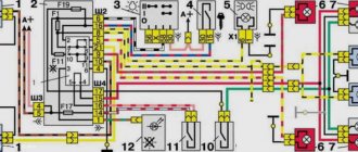
Electrical diagram of VAZ-2111 carburetor
1. block headlight; 2. front brake pad wear sensors; 3. fan motor activation sensor; 4. electric motor of the engine cooling system fan; 5. sound signal; 6. generator: 7. oil level sensor; 8. carburetor solenoid valve control unit; 9. heater controller; 10. recirculation valve switch; 11. illumination lamp for heater control levers; 12. switch; 13. carburetor limit switch; 14. oil pressure warning lamp sensor; 15. spark plugs; 16. carburetor solenoid valve; 17. coolant temperature indicator sensor; 18. ignition distributor sensor; 19. ignition coil; 20. VAZ-2111 starter; 21. heater fan electric motor; 22. additional resistor for the heater electric motor; 23. speed sensor; 24. reverse light switch; 25. micromotor gearbox for heater damper drive; 26. recirculation valve; 27. brake fluid level sensor; 28. blocks for connecting the rear window washer motor; 29. battery; 30. windshield washer motor; 31. washer fluid level sensor; 32. coolant level sensor; 33. windshield wiper gearmotor; 34. mounting block: 35. blocks for connecting the warning light harness; 36. outdoor lighting switch; 37. instrument cluster; 38. rear fog light switch; 39. fog light indicator lamp; 40. indicator lamp for heated rear window; 41. watch; 42. rear window heating switch; 43. steering column switch; 44. block for switching wires when installing headlights of a different type; 45. instrument lighting regulator; 46. ignition switch; 47. connectors for connecting the headlight cleaner wiring harness; 48. socket for a portable lamp; 49. lamp for individual interior lighting; 50. brake light switch; 51. interior lamp; 52. on-board control system unit; 53. fuel level indicator sensor; 54. hazard warning switch VAZ-2111; 55. driver's seat belt sensor; 56. cigarette lighter; 57. ashtray illumination lamp; 58. glove compartment lamp switch; 59. block for connecting the on-board computer; 60. glove box lighting lamp; 61. side direction indicators; 62. switches in the front door pillars; 63. switches in the rear door pillars; 64. parking brake warning lamp switch; 65. trunk lighting; 66. temperature sensor for the heating system; 67. external rear lights; 68. internal rear lights; 69. license plate lights; 70. rear window heating element; 71. block for connecting an additional brake light for VAZ 2111.
Wiring diagram for VAZ 2111 injector
- 1 – block headlight
- 2 – front brake pad wear sensors
- 3 – sound signal
- 4 – cooling system fan
- 5 – reverse light switch
- 6 – battery
- 7 – generator
- 8 – oil pressure warning lamp sensor
- 9 – oil level sensor
- 10 – spark plugs
- 11 – nozzles
- 12 – idle speed regulator
- 13 – electronic control unit blocks
- 14 – throttle position sensor
- 15 – crankshaft position sensor
- 16 – ignition module
- 17 – coolant temperature indicator sensor (for instrument cluster)
- 18 – starter
- 19 – diagnostic block
- 20 – coolant temperature sensor (for engine management system)
- 21 – speed sensor
- 22 – fuel pump activation relay
- 23, 35, 39 – fuses
- 24 – electric fuel pump
- 25 – micromotor gearbox for heater damper drive
- 26 – recirculation valve
- 27 – heater fan
- 28 – windshield washer pump
- 29 – washer fluid level sensor
- 30 – brake fluid level sensor
- 31 – coolant level sensor
- 32 – windshield wiper gear motor
- 33 – additional heater fan resistor
- 34 – injection system power supply relay
- 36 – adsorber purge valve
- 37 – mass air flow sensor
- 38 – relay for turning on the cooling fan
- 40 – external lighting switch
- 41 – knock sensor
- 42 – oxygen concentration sensor (heated lambda probe)
- 42* – CO potentiometer (installed on cars running on leaded gasoline; in this case, an oxygen concentration sensor is not installed)
- 43 – fog light indicator lamp
- 44 – indicator lamp for heated rear window
- 45 – fog light switch
- 46 – rear window heating switch
- 47 – instrument cluster
- 48 – mounting block
- 49 – fuel level sensor
- 50 – ignition switch
- 51 – instrument backlight brightness control
- 52 – steering column switch
- 53 – backlight lamp for heater control levers
- 54 – hazard warning switch
- 55 – electronic heater control unit; 56 – recirculation valve switch
- 57 – display unit of the on-board control system
- 58 – side direction indicators
- 59 – temperature sensor for the heating system
- 60 – interior lamp
- 61 – front interior lamp
- 62 – socket for a portable lamp
- 63 – electronic watch
- 64 – switches in the front door pillars
- 65 – switches in the rear door pillars
- 66 – glove box lighting lamp
- 67 – glove box lighting switch
- 68 – cigarette lighter
- 69 – ashtray lighting lamp
- 70 – brake light switch
- 71 – rear window heating element
- 72 – external rear lights
- 73 – internal rear lights
- 74 – license plate lamps
- 75 – trunk lighting lamp.
Contactless ignition circuit 2110
This is an example of the simplest single-cell ignition system, which, in principle, is even easier to maintain and configure than the old-style contact ignition.
Video on the electrical diagram of the VAZ 2110
https://youtube.com/watch?v=SfCG2tKNvUs
The ignition system consists of:
- battery;
- breaker;
- distributor relay;
- spark plugs;
- electronic ignition module;
- controller;
- crankshaft position sensor;
- master control disk.
In the contactless ignition circuit 2110, difficulties can arise only due to low-quality components. As a rule, ignition modules differ in this. The worst thing about this situation is that you can’t check them in the store, and the functionality of the device can only be determined on the go. Malfunctions of the electronic module are expressed simply - the absence of a spark on the spark plugs.
Low-quality components affect the quality of operation of the contactless ignition circuit 2110
However, if we delve deeper into the process of finding a spark, we can start using our color scheme, which is what we will do:
- The module may simply not receive an impulse from the crankshaft rotation sensor, but the module itself may be completely working. To verify this, it is enough to measure the voltage at the sensor output with a tester. If the pulse does not arrive and the wires are visually intact, then the sensor should be replaced.
- The module itself may not work. It is checked with an oscilloscope, but not every physicist and radio engineer has this thing in their garage, so they test it using a tester, and if there are no results, then it is replaced.
- Let's check the high voltage circuit. If there is no spark at all 4 spark plugs, then the issue is most likely with the center wire or its contacts in the breaker. Wires are checked one by one, and any broken or visually damaged wires are replaced.
- If repairs have been carried out and the engine refuses to start, you need to check the connection of the high-voltage wires in the order of cylinder operation - 1-3-4-2.
Let's leave the questions about ignition adjustment alone for now, since this is a separate story; today there is a more important question.
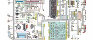
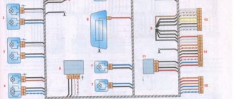
VAZ 2111 engine control circuit
- 1 — fragment of the mounting block.
- 2 — electric fan of the engine cooling system.
- 3 - status indicator of the car anti-theft system.
- 4 — control unit of the automobile anti-theft system.
- 5 — coolant temperature sensor.
- 6 — air flow sensor.
- 7 - throttle pipe.
- 8 - block connected to the throttle position sensor.
- 9 - block connected to the idle speed regulator.
- 10 – VAZ 2111 controller.
- 11 - block connected to the air conditioner wiring harness.
- 12 — oxygen sensor.
- 13 - knock sensor.
- 14 - crankshaft position sensor.
- 15 - speed sensor.
- 16 – adsorber.
- 17 - battery.
- 18 - main relay.
- 19 - block connected to the wiring harness of the anti-lock brake system.
- 20 — diagnostic block.
- 21 - main relay circuit protection fuse.
- 22 - controller protection fuse.
- 23 - fuse for protecting the electric fuel pump and its relay.
- 24 - relay for turning on the electric fuel pump.
- 25 — relay for turning on the electric fan.
- 26, 27 — blocks connected to the instrument panel wiring harness.
- 28 — ignition module.
- 29 - electric fuel pump with fuel level sensor.
- 30 - spark plugs.
- 31 – injectors.
Purpose of the plugs in block 26: 1 - to the low-voltage input of the tachometer in the instrument cluster; 3 - to the “Engine fault” lamp in the instrument cluster (from the controller); 4 - to the lamp switch located on the driver's door pillar; 5 - to the “Engine fault” lamp in the instrument cluster (supply “+” power); 6 — to the trip computer (fuel consumption signal); 7 - to the instrument cluster (vehicle speed signal 2111); 8 – to terminal “15” of the ignition switch (plug 4 of the switch block).
Common faults
As you can see, in general, the electrical circuit of the VAZ 16-valve engine is a rather complex system. Accordingly, there are also enough breakdowns in its operation; all of them can be divided into several groups. For example, if you have suspicions about the functionality of the spark plugs, but they turned out to be working, then you need to check the operation of the ignition coil and high-voltage cables. As practice shows, breakdowns in the wires can also lead to incorrect operation of the ignition system. Failure of one or another element of the electrical network can be a consequence of either a breakdown of the device itself or a failure of the generator unit or battery.
1. Connection diagram for the washer unit
2. Motor control circuit
3. Connection diagram for tidy
Most often, car owners are faced with the problem of battery failure, so let’s look at the main malfunctions characteristic of this device:
- a short circuit has occurred between the electrodes of the device;
- damage to the plates located inside;
- the appearance of cracks and other mechanical damage on the battery case, as well as shedding of the plates, which can lead to leakage of electrolyte;
- oxidation of the battery terminals, this problem can be solved by stripping.
All these faults ultimately lead to battery discharge. If we talk about the reasons that caused these problems, then most likely they all lie in incorrect operation, of course, if the battery life is high and has not yet expired. Much less often, the malfunction lies in a manufacturing defect, but this happens infrequently.
To prevent malfunctions in the operation of the battery, the following rules should be taken into account during operation:
- Firstly, the device must be securely fixed at the landing site. If the battery is not secured securely, this can lead to constant vibration, which can subsequently cause cracks in the case.
- Operation of the car and, accordingly, the use of the electrical network is allowed only when using a working generator. If the alternator is faulty or its belt tension is weak, it will ultimately lead to battery discharge.
- If the contact at the device terminal is poor, this can lead to its oxidation and destruction.
- Cranking the starter for a long time when trying to start the engine also contributes to battery discharge. This problem especially often manifests itself in cold weather, when the battery electrolytes are less mobile, and the driver has to turn the starter longer to start it (the author of the video is Vyacheslav Kravchenko).
Depending on the type and manufacturer, the battery life can range from three to five years. However, the service life may be shorter if the battery is used intensively and in harsh conditions. One way or another, the consequence of battery discharge is always the same - the device will not be able to crank the starter to start the engine, as well as power the devices and equipment of the car as a whole. If the diagnostics show that the battery is working normally, the cause of the malfunction may lie in the performance of the generator.
Its design as a whole is more complex; accordingly, this unit has a lot of faults:
- erasing of brushes due to their wear;
- voltage regulator relay failure;
- failure of the diode bridge;
- bearing wear, which is accompanied by a hum when the generator operates;
- wear of slip rings;
- damage or wear of pulley teeth;
- short circuit in the stator winding;
- damage to the charging circuit wiring;
- broken or worn alternator belt.
Malfunctions in the operation of the unit can be determined by diagnostics using a multimeter. As for repairs, you can do it yourself. We have previously described the procedure for repairing a generator using the VAZ 2114 model as an example in this article; in the case of the VAZ 2111 it looks similar.
As for other malfunctions in the operation of the electrical circuit, there may be several reasons:
- failure of the device itself;
- fuse blown caused by a short circuit (before replacing the fuse, it is necessary to determine the cause of the short circuit);
- electrical circuit breakage, the problem is solved by replacing the wire;
- oxidation of contacts on device terminals (video author - Ramanych channel).
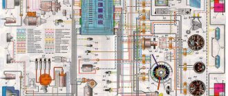
VAZ-2111 fuse block diagram
- 1 - ignition module
- 2 — speed, air flow, heating sensors
- 3 - fuel relays, pump, injectors
- 4 - fan
- 5 - fuel pump
- 6 - ignition
- F1 5 Lighting lamps: license plates, instruments, dimensions on the dashboard, left dimensions, trunk lighting
- F2 7.5 Low beam in the left headlight
- F3 10 High beam in the left headlight
- F4 10 Right front fog lamp
- F5 30 Door windows
- F6 15 Portable lamp, cigarette lighter
- F7 20 Radiator fan, sound signal
- F8 20 Heated rear window
- F9 20 Windshield washer and wiper
- F10 20 Reserve
- F11 5 Clearance on the right side
- F12 7.5 Low beam in the right headlight
- F13 10 High beam in the right headlight
- F14 10 Fog lamp, left
- F15 20 Car seat heating VAZ-2111
- F16 10 Hazard signal, turn signals
- F17 7.5 Brake light, ignition switch illumination, interior lighting
- F18 25 Cigarette lighter, glove compartment light, interior heater
- F19 10 Reversing lamp, brake light monitoring
- F20 7.5 Rear fog lights.
CAR ELECTRONICS REPAIR
Prevention measures
To prevent problems in the operation of electrical equipment, it is necessary to follow certain preventive measures, in particular:
- Charge the battery at least once a year using a charger. This is especially important to do before winter, as well as in cases where you plan to leave the car in a garage or parking lot for a long time. If the car will be parked, it is better to remove the battery altogether and charge it before installation. The battery also needs to be serviced, checking at least twice a year for the presence of electrolyte in the system and the charge of the device with the engine running and off.
- Never use low quality fuses. The same applies to the use of homemade fuses in the form of a wire or coin. Drivers usually install homemade devices if a certain fuse has failed and there is nothing to replace it with. If you are faced with the need for replacement, then, of course, a homemade version can also be used, but only in order to get to the nearest store and replace it with a normal fuse. Using homemade products can lead to short circuits and even fire.
- Always install only high-quality devices and equipment on your car - from the generator unit to the light bulbs in the dashboard. If the equipment is of low quality, its service life will not be as long, especially since its use over time can lead to inconvenience for the driver.
- If there are problems with the operation of the equipment, they must be resolved immediately. For example, you saw that the Check Engine indicator appeared on the control panel - we recommend that you check the engine as soon as possible. To obtain more accurate results, use computer diagnostics - it will help determine which node needs attention first. It should be noted that the appearance of this light is quite often due to problems in the operation of certain sensors. And their performance, in turn, can be impaired as a result of broken wiring or oxidation of contacts on the connectors. In this case, it is not necessary to immediately change the sensor - you need to change the wire and clean the contact - it is quite possible that this will solve the problem.
- If there are short circuits in the electrical circuit, they must be eliminated, since they can lead to breakdown of the electrical equipment as a whole.
- Never forget that all network elements must be reliably sealed, especially take this into account when installing equipment and wiring yourself. Auto electrical appliances and their circuits should not be affected by moisture or other factors.
Loading …