VAZ 2106 - fuses and relays
VAZ-2106
is also known under the names “Zhiguli-1600”/“Lada-1600”. Years of production: 1976, 1977, 1978, 1979, 1980, 1981, 1982, 1983, 1984, 1985, 1986, 1987, 1988, 1989, 1990, 1991, 1992, 1993, 1994, 1995, 1996, 1997, 1998, 1999 , 2000, 2001, 2002, 2003, 2004, 2005 and 2006. In this article you will find a description of fuses and relays of the VAZ 2106 with a block diagram. Let's highlight the fuse responsible for the cigarette lighter.
p, blockquote 1,0,0,0,0 —>
p, blockquote 2,0,0,0,0 —>
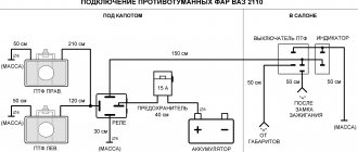
Relay and fuse block VAZ 2106: diagram decoding
The VAZ 2106 with a small-class carburetor is one of the oldest models of domestic cars that can still be found on the roads. The last copy rolled off the assembly line in 2006 and it is not surprising that this car cannot boast of such electronics as modern models. VAZ 2106 fuses play a big role in the successful operation of Lada cars.
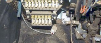
The mounting block installed under the dashboard near the driver's seat is an old model and is not designed for flag inserts, so car owners often replace it with a Euroblock. Under the lid of the box you can find a diagram with the meaning of each of the fusible elements, and their purpose can be found in the user manual. Some of the relays are also located under the shield, but some are also placed under the hood.
conclusions
Of course, in order to carry out a proper connection or upgrade, you need to know where your car's turn signal relay is located. In most models it is mounted in the fuse box. But some manufacturers put it behind the dashboard, even in the steering column. Therefore, before starting all work, make sure that you know what you are doing, study the electrical and wiring diagrams so as not to make mistakes.
Recently, LED automobile lamps have become used. They are more durable and consume less current. The latter precisely affects the operation of the turn relay, changing its frequency. The frequency of relay operation is tied to the load resistance, that is, to the installed lamps. As the load resistance increases, which is exactly what happens when one of the lamps burns out or opens, the relay begins to operate most often. The same effect is observed when installing LEDs in direction indicators, since their power consumption is less, which means the resistance is much greater.
After studying the material in this article, you will be able to modify the standard turn signal relay for LEDs so that it operates at the frequency you need.
First of all, a little about the standard relay. The 3-pin turn signal relay which will be discussed is installed on cars starting from VAZ 2108 to the present, that is, on VAZ 2109, 2110, 2111, 2112, Lada Priora, Lada Kalina, GAZ cars. Marking 495.3747-ХХ.
To modify the relay, it will be necessary to open the housing. To do this, take a flat-blade screwdriver and remove the housing cover by pulling the plastic latches from two opposite sides.
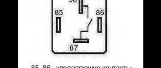
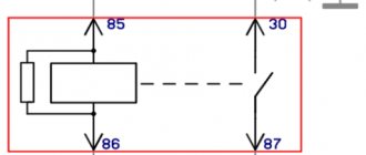
Now let’s figure out what is responsible for what in this circuit and how we can change the operation so that with increased load the frequency of operation of the direction indicators does not change. The first is connection. Ground is connected to pin 31. 49a - output to lamps, 49 - input “+” from the turn signal switch.
R3 is a current-limiting resistor to the control base of the transistor in the microcircuit; R1 and C11 - these are the radio elements that are responsible for the frequency of the output signal from pin 3 of the microcircuit. From leg 3 power is supplied to the relay winding; Conclusion 7 is also an interesting conclusion. The output controls the change in resistance and, accordingly, voltage at contact 49 a. It is he who gives the command to the microcircuit to change the frequency when the lamps burn out. The microcircuits can be not only those indicated on the diagram, but also, for example, KR1055GP1B, etc. analogues.
Now, presenting the functional purpose of the relay elements, it is not difficult to decide on measures to maintain the frequency of operation of the direction indicators when their internal resistance changes, that is, for example, when installing LEDs.
It is possible to change the capacitance value, double it (replacing it with a 4.7 µF capacitor instead of 2.2 µF - in the photo the capacitance is increased due to parallel connection of an additional capacitor to the standard one), but in this case the alarm system does not work correctly.
It will operate at half the frequency. The option of changing the resistance is also not entirely successful. Since, in fact, here you will have to empirically select a current-limiting resistor at pin 4, which is also not a very good option.
Turning relay switching diagram 495.3747
There remains the last and perhaps the best way out. In fact, remove control over load resistance. By cutting the foil on the printed circuit board (red line) going to pin 7 of the microcircuit, we will get a stable frequency response of the direction indicators.
After this modification, resistor R2 must be reduced to 60 - 200 Ohms.
The only drawback of this modification of the relay for LEDs will be the lack of monitoring of burnt-out LEDs, since we have actually removed the dependence of frequency on load resistance.
Turn signals play an important role in road safety, and their failure can lead to a lot of trouble. A small device - a turn relay - is responsible for the operation of the turn signals. Read about what types of turn relays are used in VAZ cars, how they are designed and work, as well as about their malfunctions and repairs in this article.
Fuse box VAZ 2106: diagram
The order of arrangement of fusible protective elements in the block is indicated here. This allows the car owner not to refer to the printed manual if any fuse burns. The design of the mounting block is generally consistent with other models.
Below is a table containing a list of all fuses and their ampere rating. Their total number is 16. The fusible element is responsible for 1 or several consumers - so the first of them protects the interior lighting and the socket. There are also backup elements to which new devices can be connected.
| Circuit breakers | Power, A | What protects |
| F1 | 16 | Plafonds. Sound signals. Plug socket. Cigarette lighter. Brake light bulbs in the rear lights. Signal lights for open front doors. Watch |
| F2 | 8 | Windshield wiper and wiper relay. Front window washer motor. Electric stove motor |
| F3 | 8 | Left high beam and power indicator lamp |
| F4 | 8 | Far right |
| F5 | 8 | Left Middle |
| F6 | 8 | Middle right |
| F7 | 8 | Left front, right rear. Lighting for trunk, license plate, instruments, cigarette lighter |
| F8 | 8 | Right front marker. Left rear, license plate lamp, engine compartment and warning lamps. |
| F9 | 8 | Indicator for oil pressure, coolant temperature, fuel level with reserve warning lamp, parking brake and brake fluid activation. Turn signals, battery charging, carburetor choke control, shut-off valve. Tachometer. Reversing lamps. Glove compartment lighting. Heating relay coil. |
| F10 | 8 | Voltage regulator. Generator excitation winding. |
| F11 | 8 | Reserve |
| F12 | 8 | Reserve |
| F13 | 8 | Likewise |
| F14 | 16 | Heated rear window |
| F15 | 16 | Motor cooling fan motor |
| F16 | 8 | Turn signals in hazard warning mode |
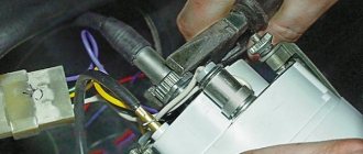
Turns relay
An indicator breaker with 3 or 4 contacts is located behind the instrument panel on the partition of the engine compartment. The rating of the light bulbs connected to the circuit should be 21 A. It looks like a rectangle.
Generator fuse and relay diagram
To check the condition, you need to get to the thermostat, since it is located directly below it. It is attached to the generator with two screws and connected with a wire that often frays. This is true for the VAZ 2106 modification with an injector. Without it, the power supply to the generator excitation winding will be unstable.
Starter relay
You can easily find the retractor, as well as remove it yourself. You need to disassemble the starter using screwdrivers. You will need to correctly install a new one in its place.
High and low beam fuse and relay
The elements F5 and F6 are responsible for the first one, and F3 and F4 are responsible for the distant one. The power of each is 8 A.
Instrument lighting
The panel lamps protect an 8 Ampere F7 fuse element.
Wipers
If they don't work or something constantly clicks when you turn them on, then the relay is broken. It is located under the dashboard on the left. Their insertion is F2.
Ignition fuse and relay
Located next to it on the power cord.
VAZ 2106 heater fuse: where is it located?
Resistor F2 and has a nominal value of 8 A.
Signal
F1 16 Ampere.
Fuse and charging relay
Located in the front wheel area on the left arch under the hood. Without it, a stable charge supply is impossible. In case of failure, the control lamp will blink.
The cost of the relay regulator article 611.3702-14 ranges from 400-500 rubles. More details about the features of this device in the video:
Wiper
The 8 Ampere protective fuse element F2 is responsible.
Cooling Fan
The relay is installed on top of the left mudguard under the hood. Fuse F15 16 Ampere.
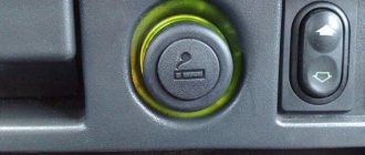
Cigarette lighter fuse
The 16 A element F1 is responsible for protection.
VAZ 2106 rear window heating relay: where is it located
An element marked PC527 can be found behind the dashboard if the option is installed.
Alarm
The breaker relay can be found on the partition of the engine compartment, which is located behind the instrument panel. F16 with a rating of 8 A is responsible for protecting the sound and light alarm.
Dimensions
The fuses F7 and F8, which are rated for 8 Amperes, are responsible.
Reverse
Element F9 with a nominal value of 8 A corresponds.
Relay 702 VAZ 2106: what for
Responsible for the operation of the charge indicator lamp.
Relay 527
Responsible for the operation of high and low beams, as well as the temperature sensor of the engine cooling fan.
Radiator fan fuse
F15 16 Ampere.
Handbrake relay VAZ 2106: where is it located
On the parking brake.
Tachometer
It is protected by fuse F9 rated 8 A.
Radio tape recorder
It is connected to one of the backup fuses.
Washer
The protective element is marked F2 and is rated at 8 A.
Distributor
Can be found near his slider at the top.
Parking brake
The relay is located behind the dashboard of the VAZ 2106, has a round shape and is made of aluminum.
Fuse F1
If the interior lighting or socket does not work, the 16 Amp fuse element that is responsible for them may have burned out.
Relay for low and high beam headlights
Glow plug relay
Almost all cars are equipped with electronic or electromagnetic relays. The fact is that devices that tend to consume too much current can easily burn the contacts, which disrupts the operation of the device itself. To prevent this from happening, relays began to be used in cars. In this article we will reveal what the low and high beam relay is, how to find out if it is faulty and how to replace it?
What is the headlight switch relay and where is it located?
A relay is an electrical device designed to switch or protect electrical circuits. In the electrical equipment of a car, these are important elements, without which the operation of many electrical appliances becomes impossible. The fact is that the battery and generator are sources of high current. As the current in the circuit increases, the temperature of the conductors also increases. This has an unfavorable effect on the switch contacts, which simply burn out. The contact surface area of the contacts is disrupted, which means the electrical resistance increases. As a result, the electrical appliance does not work.
Reducing the current is only possible when using batteries with low voltage. However, low voltage currently does not allow starting the engine and operating many consumers, so this method is unacceptable.
The solution to the problem is the use of special relays. When the contacts of the switch of the electrical receiver are closed, the relay is the first to receive current, which reduces the current strength and closes the electrical circuit with its contacts. Older cars used electromagnetic relays, the main element of which was a coil with a core. Gradually, they were replaced by electronic relays built on semiconductor elements.
Basic relay faults
Relay malfunctions can be judged if the headlights suddenly stop working. First of all, you need to check the fuse responsible for this electrical circuit. If it does not burn out, the lamps are checked using a direct connection to the battery. Usually, if all the lamps refuse to work, then we can confidently assume that the problem concerns only the light relay.
All cars use two relays. The first is responsible for the operation of the low beam headlights, the second ensures the operation of the high beam. The inclusion of side lights can be controlled either by a separate relay, or connected to one of the other two. During the process of switching the light, the operation of the device is accompanied by a characteristic click, which indicates the operation of the device and that the light has actually switched.
How to change the headlight relay with your own hands?
If the low beam does not work, find the relay of the appropriate nomenclature and pull it out. The installation of the relay depends on the make of the car. In some, a special mounting block is provided for this, and in early cars the relay is attached to the body by means of a “ground”. If in the case of the first everything is clear, then the second must first be freed from the contact wires, then the mass must be unscrewed. Before carrying out work, be sure to disconnect the negative terminal of the battery.
In place of the low beam relay, install another relay, for example, high beam and check the functionality of the optical device. If the low beam works, then the relay needs to be replaced. This is done quite simply: a new one is installed in place of the old one and connected, similar to the old element.
The same check can be carried out in relation to other operating modes of vehicle optics
When conducting diagnostics, the most important thing is to pay attention to the designations and markings of devices. If the current values differ markedly, then it is not allowed to check the functionality of the low beam using the high beam relay
In this case, it is best to purchase a new one and try to turn on the low beam using it.
If, after changing the relay, the low beam still does not work, it means that the relay is working properly and the problem should be looked for in the wiring, circuit protection devices, or in the lamps themselves for the corresponding light operating mode.
That's all you need to know about the low and high beam relays. As you can see, diagnosing and replacing devices is not difficult, and therefore you can do without an auto electrician and save a certain amount. We wish you good luck on the roads!
How to identify a blown fuse
There are two ways:
- visual inspection;
- diagnostics with a multimeter.
Visual inspection
It is necessary to check the integrity of the metal partition of the element. If it is broken, then the insert is burned out.
Diagnostics with a control and a multimeter
When an element burns out, the integrity of the jumper is not always compromised. It wouldn't hurt to check with a multimeter. The probe is applied to the fuse, the device is turned on, and if it shows resistance other than 0 Ohm, then the element is broken.
How is an electromagnetic relay connected?
But if you look more closely, the turn signal relay circuit is somewhat different; it is based on different principles. In order to turn on the device using a relay, it is necessary to apply a constant voltage to the coil (one end is constantly connected to ground, and the other to plus through a button with a latch or switch).
The design of the electronic turn signal relay consists of two main parts. From a standard electromagnetic relay that performs switching and an electronic key that provides a certain frequency of operation of this device.
The nichrome string has been replaced with an electronic key. With its help, voltage is supplied and removed from the winding of the electromagnetic relay at certain intervals. The key is based on microcircuits or discrete elements. They are components of the master oscillator and control circuits.
What kind of lighting do you prefer?
Built-in Chandelier
Expert opinion
It-Technology, Electrical power and electronics specialist
Ask questions to the “Specialist for modernization of energy generation systems”
Turn signal connection diagram: how to connect via a relay When one of the signal lamps burns out, the current passing through the winding of the reed relay decreases and its contacts open. Ask, I'm in touch!
Fuse and relay block VAZ 2106
The fuses on the VAZ 2106, as well as on other classic models, tend to fail frequently. Because of this, the car's electrical appliances do not work, which greatly affects driving safety. Therefore, you need to understand and consider the diagrams of the old and new mounting block samples and understand which fuse-link is responsible for what.
- VAZ 2106 fuse box pinout, diagram
- Relay VAZ 2106
- "Euroblock" VAZ 2106 (new model), diagram
- Replacing the VAZ 2106 fuse box with a “Euroblock”
Turning relay VAZ 2101 replacement with an electronic relay.
If desired, you can replace the electromagnetic-thermal relays of the VAZ 2101 with an electronic relay used on VAZs of subsequent brands. The connection is made in almost the same way. In addition to the standard wires, it is necessary to add only one wire connecting the electronic relay to the vehicle ground. In this case, you can also connect an alarm button.
“If you notice an error in the text, please highlight this place with the mouse and press CTRL+ENTER” “If the article was useful to you, share the link to it on social networks”
vote
Article rating
VAZ 2106 fuse box pinout, diagram
If you have any problems with electrical equipment: the low or high beams have disappeared or are not working, the turn signals, stove, cigarette lighter, fan, wipers are not working, the signal has disappeared, etc., then this could all be the reason that the fuse has blown. This means it needs to be replaced.
To do this, you need to know the location of the mounting block. And it is located under the steering wheel, on the left side. In order to understand what the VAZ 2106 fuses are responsible for, you need to look at the simple pinout of the old fuse block (FB) and see the description below.
Table “VAZ 2106 fuse designations”
| Fuse number | Current, A | What is he responsible for? |
| 1 | 16 | 1. Lamps 2. Horns 3. Power socket 4. Cigarette lighter 5. Rear lamps 6. Front door open warning lamps 7. Clock |
| 2 | 8 | 1. Windshield wiper and wiper relay 2. Wiper motor 3. Heater motor |
| 3 | 8 | Left headlight (high beam) and high beam indicator lamp |
| 4 | 8 | Right headlight (high beam) |
| 5 | 8 | Left headlight (low beam) |
| 6 | 8 | Right headlight (low beam) |
| 7 | 8 | 1. Left front marker 2. Right rear marker 3. Trunk light 4. License plate light 5. Instrument lights 6. Cigarette lighter light |
| 8 | 8 | 1. Right front marker 2. Left rear marker 3. License plate light 4. Engine compartment lamp 5. Side light indicator lamp |
| 9 | 8 | 1. Oil pressure sensor with warning lamp 2. Coolant temperature sensor 3. Fuel level with reserve warning lamp 4. Parking brake activation and brake fluid level warning lamps 5. Turn signals and corresponding warning lamps 6. Battery charge warning lamp 7. Control lamp carburetor choke control lamp 8. Carburetor shut-off valve 9. Tachometer 10. Reversing lamps 11. Glove compartment lamp 12. Rear window heating relay coil |
| 10 | 8 | 1. Voltage regulator. 2. Generator excitation winding |
| 11 | 8 | Spare |
| 12 | 8 | Spare |
| 13 | 8 | Spare |
| 14 | 16 | Heated rear window |
| 15 | 16 | Engine cooling fan |
| 16 | 8 | "Emergency" |
Lighting repair
Possible causes of malfunction
How and where to connect the DVR in a car correctly How to conduct, lay the wire from the DVR diagram
So, if the low beam on a VAZ 2106 in one of the headlights has disappeared, then, as mentioned above, most likely the light bulb has burned out.
If replacing the lamp does not produce results, then the following malfunctions may occur:
- The contacts in the block are oxidized or burnt;
- The fuse has blown;
- The relay has failed;
- The switch is faulty;
- There is a break in the circuit.
Below we will take a closer look at how to diagnose and fix the problem.
H4 standard double filament bulb
Replacing a light bulb
First of all, it should be said that the low beam lamp on the VAZ 2106 complies with the H4 standard, i.e. it has two threads, which allows the headlight to operate in two modes. Currently, such light bulbs are produced by different companies, both well-known brands and little-known companies.
It should be noted that domestic light bulbs are very popular among car owners. Their price is significantly lower than their imported counterparts, but at the same time they are not inferior in quality.
Instructions for doing this work look like this:
First of all, you need to use a flat-head screwdriver to dismantle the plastic panel that frames the headlights.
The photo shows the dismantling of the plastic panel
- Then use a Phillips screwdriver to loosen the clamps that hold the headlight.
- Next, you need to slightly turn the metal hoop and dismantle it.
Headlight fixing screws
Now you can pull out the headlight with your own hands and disconnect it from the block
At this stage, you need to pay attention to the connector contacts. If necessary, they need to be cleaned. Then you need to unfasten the lock and remove the light bulb. Next, the work is performed in the reverse order - a new lamp is installed, which is pressed with a clamp, and the block is connected to the contacts
The headlight assembly must be installed in place and secured with a hoop. To complete the work, a plastic panel is inserted, on which you need to press lightly until you hear a characteristic click.
This completes the process of replacing the light bulb.
Replacing fuses
If after replacing the light bulb the low beam headlight on 2106 still does not light, you should check the fuses. They are located under the instrument panel.
Fuse box location
In this case, you need to pay attention to two fuses:
- No. 5 – protects the left headlight from short circuit;
- No. 6 – protects the right headlight.
It must be said that the low beam on the VAZ 2106 often does not work due to the fuse contacts being bent or oxidized. In this case, they need to be bent and cleaned. If the protective element has melted, it must be replaced.
Fuse diagram
Troubleshooting other problems
If the low beam on a VAZ 2106 does not light up, then to detect a malfunction you will need a multimeter to test the wiring, or at least a test light. The circuit and equipment should be checked according to the diagram below.
Headlight switching diagram
It must be said that the high and low beam relays on the VAZ 2106, which are indicated in the diagram as numbers 6 and 4, often fail.
Therefore, you can start checking with them.
Low beam relay for VAZ 2106 (no. 3)
- If there is no voltage supplied to the relays and fuses, you should check the wiring section from switch No. 5 to terminal No. 86 on the relay, as well as the section from the switch to the external lighting switch No. 8. If the machine's wiring is normal, then the switch has failed.
- If voltage is supplied to the fuses, then an open circuit must be looked for in the area from the block to the headlights. Often the breakdown is due to poor ground contact. In this case, you just need to clean the contact.
These, in fact, are all the reasons why external lighting may not work on the “six”.
Fuse and relay diagram for VAZ 2106
| № | A | Purpose |
| Main unit 41.3722 | ||
| 1 | 16 | Cigarette lighter , brake lights, horn, clock, interior lamps, socket for portable lamp |
| 2 | 8 | Windshield wiper and washer motors, wiper relay, heater motor |
| 3 | 8 | High beam (left headlight), high beam indicator lamp |
| 4 | 8 | High beam (right headlight) |
| 5 | 8 | Low beam (left headlight) |
| 6 | 8 | Low beam (right headlight), rear fog lamp |
| 7 | 8 | Side light (left sidelight, right rear light), trunk light, right license plate light, instrument lights, cigarette lighter light |
| 8 | 8 | Side light (right sidelight, left rear light), left license plate light, engine compartment lamp, side light warning lamp |
| 9 | 8 | Turn signals and associated warning lamp, oil pressure indicator with warning lamp, coolant temperature indicator, reverse lamps, fuel level indicator with reserve warning lamp, parking brake and brake fluid level warning lamp, battery charge warning lamp, solenoid valve carburetor, tachometer, glove compartment light, carburetor choke indicator light, rear window heating relay coil |
| 10 | 8 | Voltage regulator, generator field winding |
| Additional unit PR-120 | ||
| 11 | 8 | Spare |
| 12 | 8 | Spare |
| 13 | 8 | Window lifters |
| 14 | 16 | Rear window heating element |
| 15 | 16 | Cooling fan motor |
| 16 | 8 | Direction indicators in hazard warning mode |
Breaker relay malfunctions
Malfunctions in the operation of the turn signal or low/high beam relays in the VAZ 2106 are quite rare. These mechanisms are quite reliable, but, being part of the overall electrical circuit of the car, they are not immune to problems such as overvoltage, breakdown, etc. In fact, the products are non-repairable - it is almost impossible to eliminate damage to the coil or contacts qualitatively. In other words, if a defect or malfunction is detected, the mechanisms are simply replaced with similar ones, selecting them by catalog number:
- for the turn signal relay - 231.3747-10(11) or 23.3747-10(11);
- for the lighting breaker relay - 113.3747-10(11) or 90.3747-10(11).
The number at the end of the designation indicates the design of the device case: the 10th modification is equipped with a mounting flange, while the 11th version does not have it, which is compensated by the increased dimensions of the case. Also, when choosing electronic relay breakers, you should remember that rotary models are compatible with alarm relay units, and lighting ones are compatible with devices for switching on the fan motor, horn, and rear window defroster. A malfunction of the relay unit may be indicated by problems in the operation of the light bulbs controlled by it due to the impossibility of closing the circuit or, conversely, opening it.
For rotary relays, typical signs of a malfunction may include flashing too fast or too slow, or no clicks. But the rapid blinking of the control light on the dashboard indicates that the lamp in the headlight has burned out, and not the relay itself.
Not protected by fuses
- Starter
- Ignition system
- Battery charging circuit
- Low beam relay
- High beam relay
Thermobimetallic fuses
- Windshield wiper (since 1985) - integrated into the electric motor circuit
- Window lifters - integrated into the electric motor circuit
- Hazard warning and turn signal relay ('77-'85 - 23.3747
, '85-'01 -
231.3747
) - mounted on the front panel behind the instrument cluster. - Battery charge indicator lamp relay (PC 702) - secured to the right side member mudguard in the engine compartment with two self-tapping screws. A ground tip is installed under one of the screws.
- The low beam headlight relay - B
(113.3747, 90.3747 (RS 527)) - is mounted on the mudguard of the right side member in the engine compartment. - Headlight high beam relay - A
(113.3747, 90.3747 (RS 527)) - is mounted on the mudguard of the right side member in the engine compartment. - Windshield wiper relay (PC 514) - installed under the instrument panel on the driver's side and attached to the body with two screws.
- Voltage regulator (PP 380, RS 702, RS 121, 59.3702, 592.3702, 591.3702, 591.3702-01) - mounted on the mudguard of the left side member in the engine compartment.
- Sound signal relay (PC 528) - mounted on the mudguard of the left side member in the engine compartment.
- Cooling system fan relay (90.3747-10, 113.3747-10) - mounted on the left side member splash guard in the engine compartment. (not installed since 2000)
- Parking brake warning lamp relay (PC 492) - located behind the instrument panel. (Not applicable since 1994)
- Rear window heating relay - located behind the instrument panel.
Fuse and relay diagram for VAZ 2106, 21061, 21063, 21065 - equipped with an engine: 1.6L (VAZ 2106), 1.5L (VAZ 2103) or 1.3L (VAZ 21011) (1976-2001)
Can LEDs be used instead of incandescent lamps?
However, let's look at a schematic diagram that replaces an electromagnetic relay, it will be the easiest to use.
The maximum power for the load in the circuit is 150 watts. Its connection occurs in the area of the positive terminal break. If you replace the IRFZ44 series (field key) with the IRF3205, then the ability to connect 200 Watts is achieved.
At first glance, the scheme is simple, but it works quite accurately. In addition, there is no change in the lamp blinking intervals throughout the entire operation. Also, the frequency of its blinking is not related to the power of the lamp itself. This allows you to connect halogen lamps, LED lamps and high-power lamps to the circuit.
The capacitance of the capacitor and the blinking interval of the lamps are directly related. If you increase the capacitance of capacitor C2, then the blinking of the lamp will become infrequent. But if you reduce it, the blinking will speed up. The 1n4148 diode, which has low power, can be replaced with any available diode.
If the circuit reaches 80 watts, a small amount of heat will be generated in the FET area. Now the circuit based on the field effect transistor can be used. It can even be installed in place of the old relay, but its operation will be much more reliable.
And I also want to note one point: if you decide to change your car, I recommend taking a closer look at an official Jaguar dealer. Come in and look at these beauties, price, attractiveness, modernity, this car has always been placed only in the first row.
Fuses and relays VAZ 2106
The electrical equipment of the VAZ 2106 (21061) car is protected by several fuses and relays.
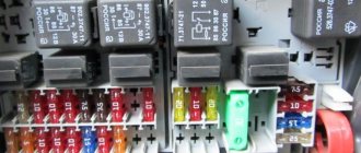
They are located in two mounting blocks (main and additional) under the instrument panel, to the left of the driver. The fuses are installed in the mounting block in numerical order - from left to right. Fuses rated 16A have a green insulator, 8A have a black insulator.
Fuses and relays for electrical equipment of the VAZ 2106 (21061) car
Main mounting block fuses
F1 (16A) - Sound signal. Plug socket for portable lamp. Cigarette lighter. Brake light bulbs. Watch. Interior lighting lamps.
F2 (8A) - Windshield wiper relay. Heater electric motor. Windshield wiper and washer motors.
F3 (8A) - High beam headlights (left headlights). Indicator lamps for high beam headlights.
F4 (8A) - High beam (right headlights).
F5 (8A) - Low beam (left headlight).
F6 (8A) - Low beam (right headlight). Rear fog lamp.
F7 (8A) - Side light (right sidelight, left rear light). Sidelight lamp. Right license plate light. Instrument lighting lamps. Cigarette lighter lamp.
F8 (8A) - Side light (left sidelight, right rear light). Left license plate light. Engine compartment lamp. Indicator lamp for turning on the dimensions.
F9 (8A) - Oil pressure gauge with warning lamp. Coolant temperature gauge. Fuel level indicator in the tank with a reserve lamp. Lamp for parking brake and brake fluid level. Battery discharge indicator lamp. Direction indicators and their indicator lamp. Carburetor solenoid valve. Tachometer. Reversing lamp. Glove box lighting lamp. Indicator for opening the carburetor air damper. Rear window heating relay coil.
F9 (8A) - Voltage regulator. Generator excitation winding.
Additional mounting block fuses
F11 (8A) - Reserve.
F12 (8A) - Reserve.
F13 (8A) - Reserve.
F14 (16A) - Rear window heating element.
F115 (16A) - Electric motor of the engine cooling system fan.
F14 (8A) - Direction indicators in hazard warning mode.
Relay VAZ 2106
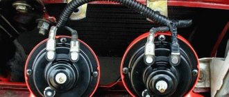
Relay for low and high beam headlights
Two relays type 90.3747 (or 113.3747). Installed on the right engine mudguard in the engine compartment.
Relay-breaker for direction indicators and hazard warning lights
Relay 231.3747 is installed behind the instrument panel. To access it you need to remove the instrument cluster.
Battery indicator lamp relay
Relay PC702 is installed on the left mudguard in the engine compartment.
Windshield wiper activation relay
The PC514 relay is installed under the instrument panel on the driver's side.
Notes and additions
— For convenience of working with the electrical wiring of the VAZ 2106 (21061) car, the wires connected to the fuses of the main unit have different colors. For example, for the first fuse the wires are red, for the second - yellow with black stripes, for the third - green with black stripes, the fourth - green, the fifth - gray with a black stripe, the sixth - gray, the seventh - yellow, the eighth - brown, the ninth - orange, the tenth is also orange.
Keys in the scheme
If you turn to the Road Traffic Rules (TRAF) in force on the territory of the Russian Federation, there are clear formulations regarding maneuvering. Before starting to move, changing lanes, changing direction, or stopping, the driver of a VAZ 2106 is required to use direction indicators, and if they malfunction, give a signal with their hands. In conditions of poor visibility, it will also be necessary to use low beam sources, and to increase the information content of the dialogue between traffic participants, also high beam ones.
The switched-on lighting is usually enough to make the car visible on the road, but no more. If you need to draw the attention of other traffic participants to a specific detail, the action, lighting should not be static, but dynamic - flashing. To put this principle into practice, you need to understand that both the headlights and indicators are part of a single electrical circuit of the “six”. In order for the indicators to blink, a periodic break in the power supply circuit of the lamps is required, and this is where a special remote key or relay is needed.
In the “six”, most of the relay breakers are located in a compact, single unit in the power compartment. At the same time, the electronic key for the turn signals and emergency lights are located inside the cabin under the dashboard. Externally and technically they are of the same type, that is, there should be no problems with interchangeability. The main tasks of these circuit components are:
- power supply for lighting lamps and direction indicators;
- periodic interruption of the circuit, creating the effect of blinking lights;
- a sound signal in the form of characteristic clicks accompanying interruptions and blinking.
Performing all the necessary functions is possible thanks to the design of the relay itself, which has two groups of contacts. Some are stationary, while others are movable, connected to an armature, and through it to an electromagnetic coil. When the latter attracts the contacts, they hit the anchors, causing characteristic clicks.