Electrical equipment diagram of a VAZ 2106 car
The VAZ 2106 car was the real culmination of many years of innovative research and development. This is a machine with reliable mechanical and electrical devices. When developing the VAZ 2106, specialists from the Volzhsky Automobile Plant were guided by the technical specifications for updating and modernizing previous models to European quality standards. Making changes to the exterior, Soviet designers developed a new design for rear lights, side turn indicators and other elements. The most popular and mass-produced car, the VAZ 2106, entered service on domestic roads in February 1976.
The design of the VAZ 2106 model included many external and internal developments
In addition to changes to the suspension and engine modifications, experts paid attention to the electrical wiring in the car, which is a system of colored wires laid side by side and tied together with insulating tape. The electrical circuit is part of the vehicle and includes a circuit designed to operate the engine and a circuit for transmitting electrical energy to lighting consumers:
- engine starting system;
- battery charge elements;
- fuel mixture ignition system;
- elements of external and interior lighting;
- sensor system on the instrument panel;
- sound notification elements;
- fuse block.
The vehicle's electrical system is a closed circuit with an independent power source. Current flows through the cable from the battery to the powered component, the current returns to the battery through the metal body of the car, connected to the battery with a thick cable. Thin wires are used for accessories and relays that require low power.
Using modern developments in design and ergonomics of the location of controls, the plant’s specialists supplemented the design of the VAZ 2106 with an emergency alarm, steering column control for wipers and a windshield washer. To effectively display technical indicators, the instrument panel was equipped with a lighting rheostat. A low brake fluid level was indicated by a separate warning light. Luxury versions of the model were equipped with a radio, heated rear window and a red fog lamp under the rear bumper.
For the first time on models of the Soviet automobile industry, rear lights are combined into a single housing with a turn indicator, side light, brake light, reversing light, reflector, structurally combined with license plate lighting.
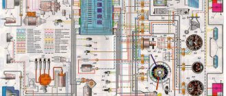
Wiring diagram VAZ 2106 (carburetor)
A complex network of wires runs through the vehicle. To avoid confusion, each wire connected to a separate element has a different color designation. To track the wiring, the entire circuit is reflected in the vehicle's service manual. The bundle of wires is stretched along the entire length of the body from the power unit to the luggage compartment. The electrical connection diagram is simple and clear, requiring explanation if problems arise with the identification of elements. Color marking is used to facilitate the process of switching electrical consumers, the detailed connection of which is indicated in the diagrams and manuals.
Color coding makes it easier to find specific electrical consumers among other elements
Table: description of electrical circuit
| Position number | Electric circuit element |
| 1 | front lights |
| 2 | side direction indicators |
| 3 | accumulator battery |
| 4 | battery charge lamp relay |
| 5 | low beam headlight relay |
| 6 | headlight high beam relay |
| 7 | starter |
| 8 | generator |
| 9 | exterior lights |
The electrical equipment system is made according to a single-wire circuit, where the negative terminals of the power consumption sources are connected to the car body, which performs the “ground” function. The current sources are an alternator and a battery. The engine is started by a starter with an electromagnetic traction relay.
To operate the power unit with a carburetor, a mechanical electric ignition system is used. The system's operation begins with the creation of a magnetic field within the ignition coil core, which forms a reservoir for the energy that will be used to ignite the spark at the spark plugs through the high voltage wires.
Activation of the entire process of starting the electrical circuit begins with the ignition switch and contact group, which control the vehicle’s ignition system, lighting system and light alarm.
The main external lighting devices are low and high beam headlights, direction indicators, tail lights and registration plate lighting. Two lampshades are used to illuminate the interior. In addition, there are door switches on the front and rear door pillars. The electrical wiring of the instrument panel includes a set of elements to notify the driver about the technical condition of the car: tachometer, speedometer, temperature indicators, fuel level and oil pressure. Six warning lamps are used to illuminate the instrument panel at night.
Main characteristics of the electrical wiring diagram:
- activation of the electrical circuit through the ignition switch;
- switching of current consumers through the fuse block;
- connecting key components to a power source.
More information about the VAZ-2106 carburetor: https://bumper.guru/klassicheskie-modeli-vaz/toplivnaya-sistema/karbyurator-vaz-2106.html
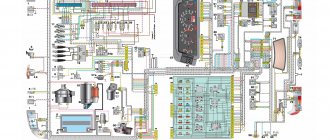
Wiring diagram VAZ 2106 (injector)
A disadvantage of a mechanical ignition system with a carbureted engine is the use of low voltage current interruption points on the primary winding of the ignition coil. Mechanical wear of contacts on the distributor cam, their oxidation and burnout of the contact surface from constant sparking. Constant adjustment to compensate for wear of the contact switches eliminates mechanical changes. The power of the spark discharge depends on the condition of the contact group, and poor sparking leads to a decrease in engine efficiency. The mechanical system is unable to provide sufficient component life, limiting spark power and engine speed.
Electronically controlled circuit diagram allows you to identify the faulty element
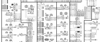
Table: description of the injector electrical circuit
| Position number | Electric circuit element |
| 1 | controller |
| 2 | electric cooling fan |
| 3 | ignition system harness block to the left mudguard harness |
| 4 | ignition system harness block to right mudguard harness |
| 5 | fuel level indicator |
| 6 | fuel level harness connector to fuel level sensor harness |
| 7 | oxygen sensor |
| 8 | fuel level sensor harness connector to ignition system harness |
| 9 | electric fuel pump |
| 10 | speed sensor |
| 11 | idle air control |
| 12 | throttle position sensor |
| 13 | coolant temperature sensor |
| 14 | mass air flow sensor |
| 15 | diagnostic block |
| 16 | crankshaft position sensor |
| 17 | canister purge solenoid valve |
| 18 | ignition coil |
| 19 | spark plug |
| 20 | injectors |
| 21 | ignition system harness block to instrument panel harness |
| 22 | electric fan relay |
| 23 | controller power fuse |
| 24 | ignition relay |
| 25 | ignition relay fuse |
| 26 | electric fuel pump power supply fuse |
| 27 | electric fuel pump relay |
| 28 | ignition system harness block to injector harness |
| 29 | injector harness block to ignition system harness |
| 30 | instrument panel harness connector to ignition system harness |
| 31 | ignition switch |
| 32 | instrument cluster |
| 33 | engine anti-toxic system display |
Read about the design of the instrument panel: https://bumper.guru/klassicheskie-modeli-vaz/elektrooborudovanie/panel-priborov/panel-priborov-vaz-2106.html
To solve the problems of the mechanical ignition system, electronic ignition was introduced. In the original systems, the contact switches were replaced by a Hall effect sensor that responded to a rotating magnet on the camshaft. New cars have removed the mechanical ignition system, replacing it with an electronic system with no moving parts. The system is fully controlled by the on-board computer. Instead of an ignition distributor, an ignition module has been introduced that serves all spark plugs. Along with the development of transportation technology, vehicles have been equipped with a fuel injection system that requires precise and powerful spark generation.
The injection system on the VAZ 2106 for supplying fuel has been installed since 2002. The previously used mechanical spark generation did not allow increasing the performance characteristics of the motor. The updated injector power supply circuit uses an electronic control circuit for the operation of the entire system. The electronic unit (ECU) controls many processes:
- fuel injection through injectors;
- fuel condition monitoring;
- ignition;
- condition of exhaust gases.
The functioning of the system begins with the readings of the crankshaft position sensor, which signals the ECU to supply a spark to the spark plugs. The electronic circuit of the injector differs from the carburetor model, suggesting the inclusion of various electronic devices in the vehicle system that transmit signals about physical and technical parameters. Thanks to the presence of numerous sensors, the electronic circuit of the injector operates steadily and reliably. After processing all the signals and parameters from the sensors, the internal memory of the microcontroller controls the operation of the fuel supply actuators and the moment of spark formation.
VAZ 2110 - modifications
VAZ-21100 . The base model which was produced from 1996 to 2000. The car was equipped with an 8-valve carburetor VAZ-21083 engine with a displacement of 1.5 liters and a power of 69 horsepower.
VAZ-21101 . This modification has been produced since 2004, equipped with an 8-valve gasoline injection engine with a displacement of 1.6 liters.
VAZ-21102. Like the previous modification with an 8-valve injection engine, but with a volume of 1.5 liters.
VAZ-21103 . Modification of the “tens” with a 16-valve injection engine with a working volume of 1.5 liters.
VAZ-21103M . A restyled modification of the VAZ-21103, equipped with a 16-valve petrol injection engine with a displacement of 1.5 liters and a power of 92 horsepower. Produced since 2002.
VAZ-21104 . The modification is equipped with a 16-valve petrol injection engine with a working volume of 1.6 liters.
VAZ-21104M . A restyled modification of the VAZ-21104, equipped with a 16-valve petrol injection engine with a displacement of 1.6 liters. Produced since 2004.
VAZ-21106 GTI . The engine of the VAZ-21106 GTI is the most powerful and expensive modification that has been produced since 2000. The car was equipped with a 2-liter 16-valve Opel C20XE gasoline engine with a capacity of 150 horsepower. The car was fitted with a body kit with swollen arches, and the track was widened by 76 millimeters. It was equipped with R15 wheels with low-profile tires.
VAZ-21106 Coupe . Coupe VAZ-21106 in a coupe body. A distinctive feature of the car was the presence of only two doors, which were lengthened by 250 millimeters, while the body was shortened by 170 millimeters. The engine was installed the same as in the previous VAZ-21106 GTI model.
VAZ 21106 WTCC . A sports modification of the 106 model, it participated in the 2008 FIA WTCC international championship.
VAZ 21107 . Modification of a car for rally competitions. It was equipped with a welded safety cage and a different suspension design.
VAZ 21108 "Premier" . A modification with a body lengthened by 170 millimeters in the rear door area, which provided more convenient entry and exit of passengers. It was equipped with a 1.5-liter injection 16-valve engine.
VAZ 21109 “Consul” . 4-seater luxury limousine based on the VAZ-2110 car. In addition to the length of the body, the dimensions of the rear door were also increased, for more convenient entry and exit of passengers. Equipped with a 1.5 liter engine and R14 or R15 wheels. Overall dimensions: length - 4950 mm, width - 1700 mm, height - 1440 mm. Fuel consumption in the urban cycle is 9.5 liters per 100 kilometers.
VAZ 2110-91 . Modification of the VAZ-2110 with a 1308 cm3 rotary piston engine. The car could reach speeds of up to 240 km/h, and acceleration from 0 to 100 km/h took 6 seconds.
A car with a 16-valve injection engine in the Gran Lux configuration includes:
- Electric windows;
- Door locking;
- Trunk lock lock;
- Velvet seat upholstery;
- Immobilizer;
- Heated front seats;
- Ventilated 14-inch brake discs;
- Rear spoiler with additional brake light;
- Fog lights.
Underhood wiring
The main part of the electrical wiring is located in the engine compartment, where the main elements, electronic and mechanical sensors of the car are located. A significant number of wires reduce the overall aesthetic appearance of the motor, surrounded by multiple cables. For convenient maintenance of the mechanical components of the engine, the manufacturer places the wiring in a plastic braid, preventing it from rubbing against metal elements of the body and hiding it in body cavities out of sight so that it does not distract attention from the power unit.
Under the hood, electrical wiring provides connection to the main elements of the power unit
Under the hood, the engine contains many auxiliary elements that consume or generate electrical energy, such as a starter, generator, and sensors. All devices are connected to each other in a certain way and in the order shown on the electrical diagram. The wires are secured in a safe and inconspicuous place, which prevents them from wrapping around moving parts of the chassis and motor.
Grounding wires are located inside the engine compartment, a tight connection of which is only permissible on a smooth metal surface. A reliable grounding contact through the car body provides a single circuit of reverse current from the negative terminal of the battery, which is the “ground” of the vehicle. The bundled cables from the sensors are placed in a protective casing that provides insulation from heat, liquids and radio interference.
The wiring system located in the engine compartment includes:
- battery;
- starter;
- generator;
- ignition module;
- high-voltage wires and spark plugs;
- numerous sensors.
Diagram of brake lights, reverse lights, side lights, license plate lighting
- Front lights with side light lamps;
- Accumulator battery;
- Generator;
- Engine compartment lamp;
- Fuse box;
- Brake light switch;
- Plug socket for portable lamp;
- Reversing light switch;
- Ignition switch;
- External lighting switch;
- Speedometer with side light indicator;
- Trunk light;
- Rear lights with parking lights, brake lights and reversing lights;
- License plate lights.
Wiring harness in the cabin
Thanks to electrical wires, all sensors, components and the instrument panel function as a single mechanism, providing a single task: the uninterrupted transmission of electrical signals between interconnected elements.
A complex system of wires in the cabin ensures connection of the instrument panel with other components and sensors
The interior contains most of the elements of the vehicle that provide control of processes, monitoring their implementation and diagnosing the technical condition of sensors.
Automotive system controls located inside the cabin include:
- instrument panel and its backlight;
- external lighting elements of the roadway;
- turn signal, stop and sound warning signals;
- interior lighting;
- other electronic assistants such as windshield wipers, heater, radio and navigation system.
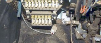
The wiring harness in the cabin ensures the connection of all elements of the car through the fuse box, which, regardless of the number of devices, is the main element of electrical wiring in the cabin. The fuse box, located to the left of the driver under the dashboard, often caused serious complaints from VAZ 2106 owners.
Fuses protect important elements of the electrical circuit from short circuits
When any wire loses physical contact, the fuses overheat, burning the fuse link. This fact was the presence of a problem in the electrical circuit of the car.
Fuses are the main elements of the electrical system
Table: designation and power of fuses in the VAZ 2106 block
| Name | Purpose of fuses |
| F1(16A) | Horn, lamp socket, cigarette lighter, brake lamps, clock and interior lights (plafonds) |
| F2(8A) | Windshield wiper relay, heater and wiper motors, windshield washer motors |
| F3(8A) | Main beam of the left headlight and high beam warning lamp |
| F4(8A) | High beam right headlight |
| F5(8A) | Left headlight low beam fuse |
| F6(8A) | Low beam right headlight and rear fog lamp |
| F7(8A) | This fuse in the VAZ 2106 block is responsible for the side light (left sidelight, right rear light), trunk light, license plate light, right light bulb, instrument lighting lamps and cigarette lighter illumination |
| F8(8A) | Side light (right side light, left rear light), license plate light left light, engine compartment light and side light warning light |
| F9(8A) | Oil pressure gauge with warning lamp, coolant temperature and fuel level indicator, battery charge warning lamp, turn indicators, carburetor choke indicator, heated rear window |
| F10(8A) | Voltage regulator and generator excitation winding |
| F11(8A) | Reserve |
| F12(8 ) | Reserve |
| F13(8A) | Reserve |
| F14(16A) | heated rear window |
| F15(16A) | Cooling fan motor |
| F16(8A) | Direction indicators in hazard warning mode |
The wiring harness is laid under the carpet, passing through technological openings in the metal body of the vehicle from the dashboard to the luggage compartment.
Engine fan diagram
- Electric motor activation sensor;
- Fan motor;
- Motor start relay;
- Main fuse box;
- Ignition switch;
- Additional fuse box;
- Generator;
- Accumulator battery.
Since 2000, a relay for turning on the cooling fan motor has not been installed, and the wires connected to the relay have been removed from the wiring harness. In addition, since 2000, the electric motor has been switched on by sensor type 661.3710. The temperature of closing the sensor contacts is (92±2.5) °C, and the opening temperature is (87±3) °C.
Features of electrical equipment maintenance and replacement of wiring VAZ 2106
Correctly laid wiring around the perimeter of the cabin and under the hood does not require special attention and maintenance. But, after repair work, the cable may be pinched, its insulation may be damaged, which will lead to a short circuit. Poor contact will lead to heating of the cable and melting of the insulation. A similar result will occur if instruments and sensors are installed incorrectly.
A long period of vehicle operation affects the condition of the wire insulation, which becomes hard and brittle, especially under the influence of significant heat in the engine compartment. Damage caused by damaged wires is not easy to find. If the damage is in the public domain without braiding, repairs are carried out without dismantling the wires.
When replacing one wire, you should label the ends of the wires located in the blocks, making a connection drawing if necessary.
Main stages of wiring replacement:
- new wiring harness for the VAZ 2106 model;
- disconnected battery from the vehicle network;
- disassembly of the instrument panel;
- torpedo disassembly;
- removing seats;
- removal of the noise-insulating coating for convenient access to the wiring harness;
- clean out corrosion that may cause poor contact;
- It is not recommended to leave exposed wires at the end of the work.
The wiring replacement procedure should not be carried out without an electrical diagram for connecting the devices to avoid confusion during installation work.
When replacing a single wire, a new one should be of the same color and size. After replacement, you should test the corrected wire with a tester connected to the nearest connectors on both sides.
Precautionary measures
Before performing work, you should disconnect the battery and insulate the sharp edges of the technological holes in the car body in places where the wires will pass to prevent a short circuit.
Sound signal circuit
- Sound signals;
- Relay for turning on sound signals;
- Sound switch;
- Fuse box;
- Generator;
- Accumulator battery.
Since 1993, one sound signal of type 20.2721-01 has been installed on cars, and it is turned on without an auxiliary relay “2”. There are two wires leading to the signal: red from plug “A” of the fuse box and gray with a black stripe from the horn switch.
Malfunctions of electrical equipment of VAZ 2106
Troubleshooting electrical problems requires special skills and following simple rules:
- a power source is required for the system to operate;
- electrical devices require constant voltage;
- the electrical circuit must not be interrupted.
The engine stalls when the washer is turned on.
The windshield washer is equipped with a switch that controls the fluid supply motor. A fault in the form of a stalled engine can be caused by grounding of the power cable, a corroded terminal, dirty or damaged wires. To troubleshoot the problem, it is worth checking all these elements and eliminating the shortcomings.
Find out more about the structure of the VAZ-2106 window lifter: https://bumper.guru/klassicheskie-modeli-vaz/stekla/steklopodemnik-vaz-2106.html
Malfunctions of the contact ignition system
The probable causes of malfunctions are:
- burning/oxidation of ignition distributor contacts (distributor);
- burning or even partial destruction of the ignition distributor cap;
- burning of the contact of the runner and its wear;
- failure of the slider resistance;
- capacitor failure.
These reasons worsen engine performance, affecting its starting, especially in cold weather. One of the recommendations is to clean the contact group of the spark plugs and the slider. If this reason occurs, the contacts of the distributor must be replaced.
Wear on the ignition cover causes damage to the runner. In this case, the parts must be replaced.
Another reason is a faulty ignition distributor noise suppression capacitor. In any case, the part must be replaced.
Wear of the mechanical part of the distributor causes shaft beating, which manifests itself in various contact gaps. The reason is bearing wear.
Ignition coil malfunctions
Starting the engine is complicated if the ignition coil is faulty, which begins to heat up significantly when the ignition is turned off due to a short circuit. The reason for the breakdown of the ignition coil is that the coil remains under voltage for a long time when the engine is not running, which leads to shedding of the winding and its short circuit. A faulty ignition coil must be replaced.
Windshield wiper and washer diagram
- Washer motor;
- Windshield wiper and washer switch;
- Windshield wiper relay;
- Wiper motor;
- Fuse box;
- Ignition switch;
- Generator;
- Accumulator battery.
Since 1985, a reusable thermobimetallic fuse has been installed in the wiper motor. It is designed to protect the electric motor from overloads.
Electrical diagrams of individual branches
The electrical equipment of the VAZ 2106 has undergone minor changes. The car has a sound signal without a switching relay and a rear fog lamp. A rear window heating system was installed on luxury cars. Most current consumers are connected via the ignition key, which allows them to operate only when the ignition is on, preventing accidental shutdown or battery discharge.
Auxiliary elements operate without turning on the ignition when the key is turned to the “I” position.
The ignition switch has 4 positions, the inclusion of which excites current in specific connectors:
- in position “0” only connectors 30 and 30/1 are powered from the battery, the others are de-energized.
- in position “I”, current is supplied to connectors 30-INT and 30/1–15, while the “dimensions”, windshield wiper, fan heating system of the heater, running lights and fog lights are energized;
- in position “II”, contact 30–50 is additionally connected to the previously used connectors. In this case, the ignition system, starter, panel sensors, and turn signals are included in the circuit.
- in position “III” only the vehicle starter is activated. In this case, the current is available only to connectors 30-INT and 30/1.
Scheme of the stove motor speed controller
If the car heater is not functioning efficiently enough, then you should pay attention to the heater fan. Automotive heating technology is simple and easy to analyze.
The problem with the heater fan operation may be a poor connection or a blown fuse.
Table: circuit diagram for switching on the interior heater fan
| Position number | Electric circuit element |
| 1 | generator |
| 2 | accumulator battery |
| 3 | egnition lock |
| 4 | fuse box |
| 5 | heater fan switch |
| 6 | additional speed resistor |
| 7 | heater fan motor |
The problem may be poor contact, which causes the fan to stop working.
Contact ignition circuit
A simple contact ignition system presented significant problems when the contact of the slider in the distributor burned out
Table: diagram of the contact ignition system of the VAZ 2106
| Position number | Electric circuit element |
| 1 | generator |
| 2 | egnition lock |
| 3 | distributor |
| 4 | breaker cam |
| 5 | spark plug |
| 6 | ignition coil |
| 7 | accumulator battery |
Contactless ignition circuit
Installing a non-contact ignition system is an innovative option when modifying the VAZ 2106 model. This innovative approach results in a smooth rumbling of the engine, eliminates dips when accelerating sharply, and makes starting in cold weather easier.
Installing a contactless ignition system affects fuel consumption
Table: diagram of a contactless ignition system
| Position number | Electric circuit element |
| 1 | ignition distributor sensor |
| 2 | spark plug |
| 3 | screen |
| 4 | contactless sensor |
| 5 | ignition coil |
| 6 | generator |
| 7 | ignition switch |
| 8 | accumulator battery |
| 9 | switch |
The main difference between a contactless system is the presence of a pulse sensor installed instead of a distributor. The sensor creates pulses, transmitting them to the commutator, which generates pulses as in the primary winding of the ignition coil. Next, the secondary winding produces high voltage current, transmitting it to the spark plugs in a certain sequence.
Low beam electrical circuit diagram
Headlights are an important safety element responsible for improving the visibility of vehicles day and night. With prolonged use, the light-emitting filament becomes unusable, disrupting the operation of the lighting system.
Troubleshooting the lighting system should start with the fuse box.
Loss of lighting affects night driving. Therefore, a lamp that has become unusable should be replaced to increase illumination. In addition to lamps, switching relays and fuses can be causes of malfunction. When troubleshooting, you should include these items on your inspection list.
Turn signal connection diagram
When creating the VAZ 2106 model, the designers included in the list of required elements an alarm system, activated by a separate button and activating all turn signals.
Analysis of the turn connection diagram will allow you to find the cause of the malfunction
Table: symbols of the direction indicator circuit
| Position number | Electric circuit element |
| 1 | Front turn signals |
| 2 | Side turn signal repeaters on the front fenders |
| 3 | Accumulator battery |
| 4 | Generator VAZ-2106 |
| 5 | Egnition lock |
| 6 | Fuse box |
| 7 | Additional fuse block |
| 8 | Hazard and turn signal breaker relay |
| 9 | Charging fault indicator light in instrument cluster |
| 10 | Hazard warning button |
| 11 | Turn indicators in rear lights |
There are no particular difficulties in working with the electrical system of the VAZ 2106 car. Constant careful care and concern for the cleanliness of contacts is required. It is important to do everything competently and carefully, prolonging the life of important components and assemblies.
Low/high beam circuit
- Headlights;
- Fuse box;
- Speedometer with high beam headlight indicator;
- Relay for low beam headlights;
- Headlight switch;
- Headlight high beam relay;
- Generator;
- External lighting switch;
- Accumulator battery;
- Ignition switch.
Differences in work
Advantages
So, what are the benefits received by the car owner whose car has injection installed:
- There is less chance of stalling when starting from a standstill - the electronics react more flexibly to the operation of the gas pedal, allowing you to move off more confidently from idle;
The engine compartment wiring harness of the VAZ 2107-20 has different connectors
- Easy engine starting - there is no need to manually operate the choke knob;
- Reduced warm-up time for a cold engine - the electronic system optimizes the minimum stable speed. You can start moving after starting, without fear of jerks and dips typical of a carburetor;
- Reduce routine maintenance of electrical equipment . In particular, there is no need to constantly adjust the gap in the breaker contacts;
For reference: Other domestic car factories also modernized electrical equipment, in particular the ignition system - see the publication on the UAZ 31514 wiring diagram.
- Reduced adjustment work on the carburetor - electronics can reduce fuel consumption and make engine operation more environmentally friendly.
In the video you can see the stable start of the VAZ 2107 injection engine.
Flaws
The injection system also has some flaws, in particular:
- Without a diagnostic tool, it is quite difficult to identify a malfunction in the engine management system;
- Standard wiring 2107 does not allow troubleshooting using a warning lamp;
- The factory instructions most often instruct you to contact a service center for diagnostics. However, the price of such a service is not always justified for the car owner.
In the photo - diagnostics of the oxygen sensor of the VAZ 2107
What's new
The main innovation was the replacement of the mechanical functions of the ignition system and preparation of the air-fuel mixture with electronic devices, which are more accurate and efficient. The wiring diagrams of the VAZ 2112 and the Samara family also underwent a similar modernization. Accordingly, the wiring of the VAZ 2107 to the injector received differences from the carburetor version.
Under the hood of the VAZ 2107-20, the absence of a carburetor and distributor is immediately striking
ECM functions
The electronic engine control system (abbr. ECM) took on the following operating parameters of the power unit:
- Controlling the amount of air and gasoline entering the car engine cylinders,
- crankshaft speed
- Spark plug control;
- Adjustment of ignition timing in all operating modes;
- Turning the electric fuel pump on and off,
- Control of the electric fan of the engine cooling system.
The photo below shows a VAZ 2107 wiring diagram for an injector with an M1.5.4N ECM and a January-5.1.3 controller
Injection system VAZ 2107
Electrical diagram
The classic 2107 wiring on cars with an injection system has also undergone changes. In particular, under-hood elements equipped with connectors for sensors and electronic devices have appeared.
Electrical diagram of VAZ 2107 with carburetor
For reference: The developers of Moskvich 2141 followed a similar path. True, they had a more global problem - the lack of their own engine.
Explanation for the electrical diagram of the carburetor VAZ 2107
For reference: The photo below shows the electrical wiring of a VAZ 2107 to an injector with catalog numbers. The differences from carburetor kits are in the engine compartment harnesses.
When converting the engine to an injection system, you should also purchase new wiring
Basic and additional diagrams of the VAZ 2109 passenger car
This article contains a color general diagram of a VAZ 2109 passenger car. For a better understanding of how to connect individual electrical devices and circuits to the overall diagram, additional electrical diagrams of these devices are presented on this page. All electrical diagrams have explanations and explanations of the designation points. At the beginning of the article there is a table of modifications of the VAZ 2109 car produced by the Volga Automobile Plant for domestic and foreign markets. It supplements information about the electrical devices of this vehicle. For additional information about the design of electrical systems, equipment and circuits of the VAZ 2109 passenger car and its modifications, there is a section of special technical literature on this page. There you can view and download the necessary catalogs and manuals for the repair and operation of these vehicles.
Wires for connecting electrical appliances
| Connection type | Section, mm 2 | Insulation color |
| Negative terminal of the battery - vehicle ground (body, engine) | 16 | Black |
| Starter positive terminal - battery | 16 | Red |
| Positive contact of the generator - plus battery | 6 | Black |
| Generator - black connector | 6 | Black |
| Terminal on the generator “30” – white MB block | 4 | Pink |
| Starter connector “50” – starter relay | 4 | Red |
| Starter Start Relay - Black Connector | 4 | Brown |
| Ignition switch relay - black connector | 4 | Blue |
| Ignition switch output “50” – blue connector | 4 | Red |
| Ignition switch connector “30” – green connector | 4 | Pink |
| Right headlight plug - ground | 2,5 | Black |
| Left headlight plug - blue connector | 2,5 | Green, gray |
| Generator output “15” – yellow connector | 2,5 | Orange |
| Right headlight connector - ground | 2,5 | Black |
| Left headlight connector - white connector | 2,5 | Green |
| Radiator fan - ground | 2,5 | Black |
| Radiator Fan - Red Connector | 2,5 | Blue |
| Ignition switch output “30/1” – ignition switch relay | 2,5 | Brown |
| Ignition switch contact “15” – single-pin connector | 2,5 | Blue |
| Right headlight - black connector | 2,5 | Grey |
| Ignition switch connector “INT” – black connector | 2,5 | Black |
| Six-pin block of the steering column switch - “ground” | 2,5 | Black |
| Two-pin block of the steering column switch - glove box illumination lamp | 1,5 | Black |
| Glove compartment light - cigarette lighter | 1,5 | Black |
| Cigarette lighter - blue block connector | 1,5 | Blue, red |
| Rear window defroster - white connector | 1,5 | Grey |
Window lifters
- Main fuse box;
- Power window relay;
- Left door power window switch;
- Right door power window switch;
- Right door electric window motor reducer;
- Left door electric window motor reducer;
- Additional fuse box;
- Ignition switch;
A - to terminal -30- of the generator;B - to the instrument lighting switch; B - conventional numbering of plugs in the gear motor block.
Wiring diagram VAZ 2114 injector 8 valves
| Here we consider various diagrams of devices and systems of the VAZ 2114 passenger car. The VAZ 2114 was produced in three modifications for the domestic and foreign markets. VAZ 2114-20 - produced in 4 trim levels with an injection engine 2111-86. VAZ 2114-21 - produced in the same configuration with the injection engine 2111-86 for the domestic market. VAZ 2114-22 - produced in three trim levels with a 2111-86 injection engine for the domestic and foreign markets. |