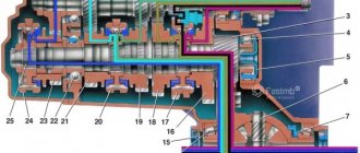
The design of the gearbox of VAZ passenger cars is shown in diagram 1. Gearbox mechanical, three-way, with constant gear mesh, with synchronizers and non-automatic (with manual control).
The box has four gears for forward movement and one gear for reverse movement. The gears of all gears (except reverse gear) are helical, which reduces noise during operation of the gearbox, and have constant meshing. The reverse gears are spur gears. Gears for forward movement are engaged using synchronizers , and for reverse movement - by moving the reverse intermediate gear. Gears are changed using a lever that has three strokes forward and backward to change gears.
VAZ 2110 gearbox diagram:
| 1 – clutch release bearing; | 18 – driven gear of the second gear of the secondary shaft; |
| 2 – guide sleeve of the clutch release bearing; | 19 – driven gear of the third gear of the secondary shaft; |
| 3 – main gear drive gear; | 20 – synchronizer for 3rd and 4th gears; |
| 4 – roller bearing of the secondary shaft; | 21 – driven gear of the fourth gear of the secondary shaft; |
| 5 – oil sump; | 22 – ball bearing of the secondary shaft; |
| 6 – satellite axis; | 23 – driven gear V of the secondary shaft transmission; |
| 7 – speedometer drive drive gear; | 24 – 5th gear synchronizer; |
| 8 – axle gear; | 25 – secondary shaft; |
| 9 – differential box; | 26 – rear cover of the gearbox housing; |
| 10 – satellite; | 27 – drive gear of 5th gear; |
| 11 – clutch housing; | 28 – ball bearing of the input shaft; |
| 12 – driven gear of the main gear; | 29 – input shaft; |
| 13 – adjusting ring; | 30 – gearbox housing; |
| 14 – tapered roller bearing of the differential; | 31 – roller bearing of the input shaft; |
| 15 – axle shaft seal; | 32 – input shaft oil seal; |
| 16 – driven gear of the 1st gear of the secondary shaft; | 33 – breather. |
| 17 – synchronizer of 1st and 2nd gears; |
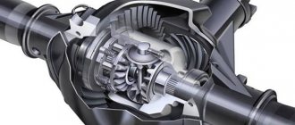
The operating scheme is as follows: the input shaft (29) is made in the form of a block of drive gears, which are in constant engagement with the driven gears of all forward gears. The secondary shaft (25) is hollow, with a removable drive gear (3) of the main gear. On the secondary shaft there are driven gears (16, 18, 19, 21, 23) and synchronizers (17, 20, 24) for forward gears. The front bearings (4, 31) of the shafts are roller, the rear bearings (22, 28) are ball. An oil sump (5) is located under the front bearing of the secondary shaft, directing the flow of oil into the secondary shaft and further under the driven gears.
The differential is two-satellite. The preload in the differential bearings is adjusted by selecting the thickness of the ring (13). The driven gear (12) of the main gear is attached to the differential box flange.
Gears and bearings
The drive gears of the system are located on the drive shaft and are combined into a block. They constantly work in conjunction with driven gears of all front transmission torques. The secondary shaft also contains gears on needle-type bearings. The main transmission system is equipped with a solid-turned gear combined with a shaft. Roller bearings are installed on the front shaft in the box, while ball bearings are located on the rear shaft. The oil reservoir is located directly under the front of the secondary shaft, where the bearing is located. The role of the collector is to determine the direction of oil flow; with the help of a torque shaft, it is directed directly inside.
A two-satellite differential is installed on the device; it is adjusted by changing the thickness of the bearing spacer ring. This spacer ring is located in the core of the gearbox housing. The differential of the box has a flange that has a clutch with a driven gear of the main transmitting moment. This gear is directly connected to the speedometer gear.
Gear shift drive diagram:
| 1 – gear selection rod lever; | 10 – hinge bushing; |
| 2 – gear selection lever; | 11 – hinge tip; |
| 3 – gearbox housing; | 12 – clamp; |
| 4 – clutch housing; | 13 – protective cover of traction; |
| 5 – gear selection rod; | 14 – gearbox control drive rod; |
| 6 – rod bushing; | 15 – gear shift lever; |
| 7 – rod seal; | 16 – ball joint cage; |
| 8 – protective cover; | 17 – ball joint of the gear shift lever; |
| 9 – hinge body; | 18 – jet thrust. |
The gearbox control drive consists of a gear shift lever (15), a ball joint (17), a rod (14), a gear selection rod (5) and gear selection and shift mechanisms (crumpled “P”).
To prevent spontaneous switching off of the P due to the axial movement of the power unit on its supports when the vehicle is moving, a reaction rod (18) is introduced into the gearbox control drive, one end of which is connected to the power unit, and a clip (16) of the ball joint of the lever (15) is attached to the other end ) switching P.
A lever (1) is attached to the inner end of the rod (5), which acts on the three-year lever (2) of the P selection mechanism. This mechanism is made as a separate unit and is attached to the plane of the clutch housing.
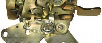
Gear selection mechanism:
| 1 – gear selection lever (forward); | 6 – reverse fork axis; |
| 2 – guide axis of locking brackets; | 7 – locking bracket; |
| 3 – axis of the gear selection lever; | 8 – reverse fork; |
| 4 – spring; | 9 – gear selection lever (reverse); |
| 5 – retaining ring; | 10 – housing of the gear selection mechanism. |
Two axles are mounted in the housing (10) of the gear selection mechanism. A three-year-old gear selector lever and two locking brackets (7 and 12) are installed on the axis (3). The other axis (2) passes through the holes of the locking brackets, securing them from turning. The gear selector lever arm (1) is used to engage P forward gear, the lever arm (9) is used to engage reverse gear, and the third arm is used by the gear selector rod lever. A fork (8) for engaging reverse gear is installed on the axle (6).
Oil is poured into the gearbox of a VAZ 2110, the level of which should be between the control marks of the oil level indicator.
Like any car, the VAZ 2110 is equipped with a gearbox. In the case of the designated model, this mechanism has 5 stages and is controlled via a shift lever, which, in turn, is located inside the car.
To ensure that there are no problems with the operation of your VAZ 2110, and that you can correct all kinds of failures yourself, you will need to understand the principles of operation and the design of the gearbox. We will also consider the process of changing the oil for the “ten”.
Gearbox VAZ 2110
The design of the gearbox is as follows: to ensure switching, the gearbox contains a so-called input shaft, which consists of a special block and gears. They are located in such a way that they are in constant mesh with the drive gears from speeds 1 to 5 (those that allow you to move forward). There is also another secondary shaft on which the main gear drive gear and synchronizers are located, which ensure forward movement. In addition, bearings and the so-called oil sump are located here.
The VAZ 2110 device assumes the presence of a two-satellite type differential. The drive part of the gearbox consists of a shift knob, a ball joint, a rod, a rod and mechanisms for selecting gears. The presence of jet thrust is explained by this - this is a measure to protect the gearbox from so-called “overshoots”. This traction is fixed with a support and a power unit.
Adjustment work with the VAZ 2110 gearbox
Many of the owners of the VAZ 2110 mention cases when shifting gears is difficult, they are difficult to engage, and there are also frequent cases when these same gears are simply knocked out. Manufacturers have made sure that for such cases there is a special adjustment mechanism for the drive to select the speed.
This mechanism will be very useful when:
- The gearbox has been removed or was previously removed for repair work.
- One of the gears fails.
- Shifting gears occurs with effort, is difficult, or they simply get knocked out while the car is moving.
Provided that one of the described problems is typical and present in your VAZ 2110, you will need to make adjustments. It consists of the following steps:
- On the bottom of your car you will need to find the nut of the bolt that tightens the clamp that secures the rod required to carry out the gearbox control process. The nut will need to be loosened.
- Next, you need to move apart the grooves at the end of the rod using a screwdriver and also the crack on the clamp. Such manipulation will be required so that the rod can easily move relative to the gear selection rod. Set the rod itself to the neutral position.
- The shift knob must be freed from the cover.
- The lever is set according to a special pattern. In the rear speed locking bracket adjustment window, a template is set. Next, a stop for the lever axis is inserted in place of the template groove, and it is necessary to press without unnecessary effort in the transverse direction.
- Next, the axial play of the rod is adjusted in the rearward direction.
- The clamp is fixed a few millimeters from the end of the rod. Next, tighten the same clamp with a bolt.
Repairing the box
In the case where this kind of adjustment work did not bring much results, you will have to remove and disassemble the gearbox of your VAZ 2110. The main attention should be paid to the gears, since they are most often knocked out. This is especially true for first and second speeds. It will also be important to check the latch.
There are three latches in total in the gearbox. The very first of them is very long and is responsible for 1st and 2nd gears. Next comes the clamp for third and fourth gears, and the shortest of the clamps is intended for 5th gear.
complete gearbox assembly
A short summary
General structure of manual gearboxes on VAZ
VAZ manual gearboxes are very reliable, unpretentious gearboxes, their gearshift scheme is the most standard, no exotic ones. And this is a huge plus, since their maintenance and repair are just as simple and straightforward. They have to be repaired relatively rarely, since they perfectly hold the torque from the ring shaft of VAZ engines, even forced ones. For comparison, many manual gearboxes have difficulty maintaining the torque of stock engines, comparable in power to VAZ ones, and very quickly fail at the slightest increase in engine power. What makes VAZ manual transmissions so durable? Let's look at the diagram of their design and understand why they are good and what their shortcomings are.
Problems
Often, VAZ 2110 owners voice a problem regarding the switching or departure of first gear. Most likely, the reasons lie in the following:
- synchronizer problems;
- damage to the retainer spring when the lever dangles and the gears are switched on randomly;
- damaged rod and fork.
A common problem is when the second gear is reluctantly engaged, or it is simply knocked out. The most likely causes of the problem:
- poor engagement of the gear and clutch that engages the gears;
- wear of gear teeth and coupling;
- problems with the clutch.
Changing the oil
According to the documentation, the lubricant component in VAZ 2110 engines and transmissions must be changed every 15 thousand kilometers or at least once a year.
So, we need to warm up the engine well and prepare the required oil and, preferably, a new oil filter, as well as the tools necessary for the job.
gearbox housing 2110
To drain the waste, you will need to unscrew the plug from the oil pan. Next, within 10-15 minutes, the oil is drained into a special container, which will need to be prepared in advance. Then the drain plug returns to its original position and is screwed tightly. Now you can replace the old oil filter with a new one (if necessary).
Now that the old oil has been drained, pay attention to its color and presence of inclusions. If the oil is dark brown in color and to the touch contains various types of inclusions such as metal dust or pieces of dirt, then the transmission will need to be flushed.
DON'T WASTE MONEY ON REPAINTING! Now you can remove any scratch from the body of your car in just 5 seconds.
For this purpose, special solutions are used, which are poured into the engine and gearbox before new oil. In this case, you will need to drive the car with such a solution for a short time and not quickly, five minutes along the garage will be enough, and then drain the mixture and the dirt that it has collected in the same way as described for the process of draining the “working off”.
In order to fill with fresh oil, you will need to remove the filler cap. In this case, from 3 to 4 liters of oil are poured into the engine, depending on the readings of the dipstick. Ideally, the oil level is between the min. marks. and max.
These marks are marked on the dipstick as the minimum and maximum values. Next, you will need to start the engine and wait until the oil light (or oil pressure light) goes out. After this, turn off the engine, check the oil level and, if necessary, remove excess or add more oil.
There are times when the light bulb just won't go off. In such cases, it is better to check the quality of the oil filter or replace it if it was not changed during the replacement process.
Product delivery options
Note! Below are the shipping methods available specifically for this product. Payment options may vary depending on the delivery method.
Detailed information can be found on the “Delivery and Payment” page.
Parcel by Russian Post
Available payment methods:
- Cash on delivery (payment upon receipt)
- Using cards Sberbank, VTB, Post Bank, Tinkoff
- Yandex money
- QIWI
- ROBOKASSA
Shipping throughout Russia. Delivery time is from 5 to 12 days.
Parcel by Russian Post 1st class
Available payment methods:
- Cash on delivery (payment upon receipt)
- Using cards Sberbank, VTB, Post Bank, Tinkoff
- Yandex money
- QIWI
- ROBOKASSA
Shipping throughout Russia. Delivery time is from 2 to 5 days. More expensive than regular delivery by Russian Post, approximately 50%. Parcel weight up to 2.5 kg
Gearbox device VAZ 2110, VAZ 2111, VAZ 2112, Lada Ten
1 – rear cover of the gearbox housing 2 – drive gear of the 5th gear 3 – ball bearing of the input shaft 4 – drive gear of the 4th gear of the primary shaft 5 – input shaft 6 – drive gear of the 3rd gear of the input shaft 7 – gearbox housing 8 – drive gear of the 2nd gear input shaft 9 – reverse gear 10 – reverse intermediate gear 11 – 1st gear drive gear of the input shaft 12 – roller bearing of the input shaft 13 – input shaft oil seal 14 – breather 15 – clutch release bearing 16 – clutch release bearing sleeve guide 17 – main drive drive gear 18 – roller bearing of the secondary shaft 19 – oil sump 20 – pinion axis 21 – speedometer drive drive gear 22 – axle gear 23 – differential box 24 – satellite 25 – clutch housing 26 – oil drain plug 27 – main drive driven gear 28 – adjusting ring 29 – tapered roller bearing of the differential 30 – axle shaft oil seal 31 – driven gear of the 1st gear of the secondary shaft 32 – synchronizer of the 1st and 2nd gears 33 – driven gear of the 2nd gear of the secondary shaft 34 – driven gear of the 3rd gear of the secondary shaft 35 – synchronizer of the 3rd and 2nd gears IV gear 36 – driven gear IV gear of the secondary shaft 37 – ball bearing of the secondary shaft 38 – driven gear V gear of the secondary shaft 39 – synchronizer V gear 40 – secondary shaft
Transmission control drive
1 – protective cover of the rod 2 – gearbox control rod 3 – gear shift lever 4 – pin of the spherical gear shift lever 5 – ball joint cage 6 – ball joint of the gear shift lever 7 – buffer 8 – spring 9 – reaction rod 10 – rod lever gear selector 11 – gear selector lever 12 – gearbox housing 13 – clutch housing 14 – gear selector rod 15 – rod bushing 16 – rod seal 17 – protective cover 18 – joint body 19 – joint bushing 20 – joint tip 21 – clamp
The gearbox is mechanical, two-shaft, with five forward gears and one reverse gear, with synchronizers on all forward gears of the VAZ 2111. It is structurally combined with a differential and main gear.
The VAZ 2111 gearbox housing consists of three parts (cast from aluminum alloy): clutch housing 25, gearbox housing 7 and rear cover of the gearbox housing 1. During assembly, a gasoline-oil-resistant gasket sealant is applied between them (for example, KLT-75TM or TB- 1215). There is a special magnet in the crankcase socket that retains metal wear products.
The input shaft 5 is designed as a block of drive gears, which are in constant mesh with the driven gears of all forward gears. The secondary shaft 40 is hollow (for supplying oil to the driven gears), with a removable drive gear of the main gear 17. Driven gears 31, 33, 34, 36, 38 and synchronizers 32, 35, 39 for forward gears are located on it. The front bearings of shafts 18 and 12 are roller, the rear bearings 3 and 37 are ball. The radial clearance in roller bearings should not exceed 0.07 mm, in ball bearings - 0.04 mm. Under the front bearing of the secondary shaft 18 there is an oil sump 19, which directs the flow of oil into the shaft.
The differential is two-satellite. The preload in the bearings 29 (0.25 mm) is adjusted by selecting the thickness of the ring 28 installed in the gearbox housing housing under the outer ring of the differential bearing. The driven gear of the VAZ 2110 main gear 27 is attached to the differential box flange.
The gearbox control drive consists of a VAZ 2110 gear shift lever, a ball joint, a rod, a gear selection rod and mechanisms for selecting and shifting gears of a VAZ 2110. Before assembly, TB-1324 thread glue is applied to the screws that secure the rod and lever to the gear selection rod. The lever and hinge mounting screws vary in length, coating and tightening torques. The lever fastening screw is phosphated (dark color), 19.5 mm long, tightened with a torque of 3.4 kgf.m. The hinge fastening screw is cadmium-plated (golden), 24 mm long, tightened with a torque of 1.95 kgf.m. LSC-15 lubricant is placed in the ball joint before assembly.
To prevent the gears from spontaneously switching off due to the axial movement of the power unit when the vehicle is moving, a reaction rod is introduced into the gearbox control drive, one end of which is connected to the power unit, and a ball joint race for the gear shift lever is attached to the other end.
A lever is attached to the inner end of the rod, which acts on the three-arm lever of the gear selection mechanism of the VAZ 2111. This mechanism is made as a separate unit and is attached to the plane of the clutch housing.
The housing of the gear selection mechanism of the VAZ 2112 has two axes. One has a three-arm gear selector lever and two locking brackets. The other axis passes through the holes of the locking brackets, securing them from turning. One arm of the VAZ 2112 gear selection lever is used to engage forward gears, the other is used to engage reverse gear, and the third arm is used by the gear selection rod lever. A reverse fork is installed on the axle.
The gearbox is filled with TM-5-9p oil at the factory, designed for 75,000 km. The oil level should be between the reference marks on the oil level indicator.
The gearbox communicates with the atmosphere through breather 14 located in its upper part.
How to repair a gearbox on a VAZ 2110
Adjustment does not always achieve the desired effect. Therefore, the motorist will need to carry out repair work. Practice shows that repairing a VAZ 2110 gearbox involves dismantling and reassembling the gearbox. Now I will tell you in detail how to do this.
How to remove/dismantle a VAZ 2110 box
How to remove the box? Before disassembling the gearbox, it must be cleaned
It is important that water does not get inside the box.
Main stages:
- Power from the battery is turned off.
- The block is disconnected from the speed sensor.
- Transmission fluid is drained.
- The bolts securing the jet thrust are removed.
- It is necessary to remove the constant velocity joints from their standard location.
- The existing ball joint bolts are loosened.
- Using a tool, unscrew the nuts holding the clutch cover to the gearbox housing.
- The bolts securing the gearbox to the engine are disconnected.
- The power plant must be lifted (use a jack).
- The engine mounts must be removed.
- To pick up the gearbox, you can use a screwdriver.
- The speed box slides off the guides. The input shaft should disengage from the clutch.
How to properly disassemble a VAZ 2110 gearbox
- We remove dirt and wash the outside of the gearbox (do not allow water to enter the crankcase).
- Using a 17mm wrench, unscrew the bolt securing the power unit suspension bracket.
- Using a 13mm socket, unscrew the six nuts securing the rear crankcase cover.
- Remove the bracket.
- Tapping with a copper hammer (or an ordinary one through a soft metal mandrel) on the tides of the lid, and remove it along with the sealing gasket from the studs.
- Having pressed the gear selection rod all the way, we turn on the third gear, or, by retracting the rod all the way, we turn on the fourth.
- Using a 10mm spanner, unscrew the bolt securing the fifth gear fork.
- Using a soft metal drift, we strike the fork downwards, including the fifth gear of the VAZ 2110
- Use a beard to straighten dents in the nuts of the primary and secondary shafts
- Using a 32" socket with a powerful wrench, unscrew the shaft nuts.
- Using a screwdriver, pry off the fifth gear fork and remove the fifth gear assembly. Remove the fifth gear shift fork.
- Remove the synchronizer sliding clutch from the hub. Remove the synchronizer blocking ring. We take out the thrust plate.
- We move the hub inside the sliding clutch of the Synchronizer and remove the hub, springs, clamps and crackers of the fifth gear synchronizer.
- Using a copper hammer we strike the end of the input shaft. Insert two screwdrivers into the resulting gap between the thrust plate and the fifth gear drive gear. Prying up the gear with screwdrivers, we press it
- Using the “13” socket, unscrew the three plugs of the gearshift rod clamps. Remove the springs and retaining balls from their sockets.
- Using a Phillips impact screwdriver, unscrew the four screws securing the thrust plate. The screws have special lock washers.
- Remove the thrust plate. Use two screwdrivers to pry off the thrust washer of the fifth gear driven gear bushing. We insert the puller arms into the resulting gap between the end of the rear bearing and the thrust washer and compress the gear sleeve and the thrust washer.
- Use two screwdrivers to separate the retaining ring on the input shaft and remove it. In the same way, remove the retaining ring from the secondary shaft.
- We insert a screwdriver into the socket of the latch and, applying a magnet to it, remove the ball.
- Using a “13” socket, unscrew thirteen nuts and one bolt securing the gearbox housing to the clutch housing.
- By inserting a screwdriver into the groove at the junction of the crankcase mating planes, carefully lift the box crankcase and remove it.
- Using a 10mm spanner, unscrew the bolt securing the 1st-2nd gear shift fork to the rod. We lift the rod up and disengage the fork. Using a 10mm spanner, unscrew the bolt securing the 3rd-4th gear shift fork to the rod. Use a screwdriver to remove the rod from the gear selection mechanism.
- Raise the rod up and remove the fork from the groove of the synchronizer sliding clutch.
- By turning the 5th gear engagement rod, we remove it from the gear selection mechanism. We take out the axis of the reverse intermediate gear.
- Remove the reverse intermediate gear. We simultaneously remove the primary and secondary shafts from the roller bearings of the clutch housing.
- We take out the differential assembly. The process of repairing a VAZ 2110 gearbox
- Using a 10mm socket, unscrew the three bolts securing the gear selection mechanism and remove it.
- Using a 10mm socket, unscrew the installation bolt of the gear selector lever. Remove the gear selector lever from the rod.
- Using a screwdriver, remove the protective cover of the rod from the bushing. We take out the gear selection rod.
Gearbox VAZ 2110
Cross-sectional design of a gearbox on a VAZ 2110
Main parts of the VAZ 2110 gearbox: 1 – rear cover of the gearbox housing, 2 – fifth gear drive gear, 3 – input shaft ball bearing, 4 – fourth gear drive gear of the input shaft, 5 – input shaft, 6 – third gear drive gear input shaft, 7 – gearbox housing, 8 – drive gear of the second gear of the primary shaft, 9 – reverse gear, 10 – intermediate reverse gear, 11 – drive gear of the first gear of the primary shaft, 12 – roller bearing of the input shaft, 13 – oil seal input shaft, 14 – breather, 15 – clutch release bearing, 16 – clutch release bearing clutch guide sleeve, 17 – main drive drive gear, 18 – secondary shaft roller bearing, 19 – oil sump, 20 – pinion axis, 21 – drive drive gear speedometer, 22 – axle gear, 23 – differential box, 24 – satellite, 25 – clutch housing, 26 – oil drain plug, 27 – main drive driven gear, 28 – adjusting ring, 29 – differential tapered roller bearing, 30 – oil seal axle shaft, 31 – driven gear of the first gear of the secondary shaft, 32 – synchronizer of the first and second gears, 33 – driven gear of the second gear of the secondary shaft, 34 – driven gear of the third gear of the secondary shaft, 35 – synchronizer of the third and fourth gears, 36 – driven gear of the fourth transmission of the secondary shaft, 37 – ball bearing of the secondary shaft, 38 – driven gear of the fifth gear of the secondary shaft, 39 – fifth gear synchronizer, 40 – secondary shaft.
Gearbox control drive VAZ 2110
VAZ 2110 backstage diagram: 1 – protective cover of the rod, 2 – gearbox control rod, 3 – gear shift lever, 4 – pin of the spherical gear shift lever, 5 – ball joint cage, 6 – ball joint of the gear shift lever, 7 – buffer , 8 – spring, 9 – reaction rod, 10 – gear selection rod lever, 11 – gear selection lever, 12 – gearbox housing, 13 – clutch housing, 14 – gear selection rod, 15 – rod bushing, 16 – rod seal, 17 – protective cover, 18 – hinge body, 19 – hinge bushing, 20 – hinge tip, 21 – clamp.
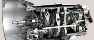
The principle of operation of the VAZ 2110 gearbox
The gearbox is mechanical, two-shaft, with five forward gears and one reverse gear, with synchronizers in all forward gears. It is structurally combined with the differential and main gear.
The gearbox housing consists of three parts (cast from aluminum alloy): the clutch housing, the VAZ 2110 gearbox housing and the rear cover of the gearbox housing. During assembly, a gasoline-oil-resistant gasket sealant (for example, KLT-75TM or TB-1215) is applied between them. There is a special magnet in the crankcase socket that retains metal wear products.
The input shaft of the VAZ 2110 is designed as a block of drive gears, which are in constant engagement with the driven gears of all forward gears. The secondary shaft of the VAZ 2110 is hollow (for supplying oil to the driven gears), with a removable drive gear of the main gear. It houses the driven gears and forward gear synchronizers. The front shaft bearings are roller, the rear are ball. The radial clearance in roller bearings should not exceed 0.07 mm, in ball bearings - 0.04 mm. An oil sump is located under the front bearing of the secondary shaft, directing the flow of oil into the shaft.
The differential is two-satellite. The preload in the bearings (0.25 mm) is adjusted by selecting the thickness of the ring installed in the gearbox housing housing under the outer ring of the differential bearing. The main drive driven gear is attached to the differential box flange.
The gearbox control drive consists of a gear shift lever, a ball joint, a rod, a gear selection rod and gear selection and shift mechanisms. TB-1324 thread glue is applied to the screws securing the rod and lever to the gear selector rod before assembly. The lever and hinge mounting screws vary in length, coating and tightening torques. The lever fastening screw is phosphated (dark color), 19.5 mm long, tightened with a torque of 3.4 kgf.m. The hinge fastening screw is cadmium-plated (golden), 24 mm long, tightened with a torque of 1.95 kgf.m. LSC-15 lubricant is placed in the ball joint before assembly.
To prevent the gears from spontaneously switching off due to the axial movement of the power unit when the vehicle is moving, a reaction rod is introduced into the gearbox control drive, one end of which is connected to the power unit, and a ball joint race for the gear shift lever is attached to the other end.
A lever is attached to the inner end of the rod, which acts on the three-arm lever of the gear selection mechanism. This mechanism is made as a separate unit and is attached to the plane of the clutch housing.
The housing of the gear selection mechanism of the VAZ 2110 has two axes. One has a three-arm gear selector lever and two locking brackets. The other axis passes through the holes of the locking brackets, securing them from turning. One arm of the gear selection lever is used to engage forward gears, the other is used to engage reverse gear, and the third arm is used by the gear selection rod lever. A reverse fork is installed on the axle.
The gearbox is filled with TM-5-9p oil at the factory, designed for 75,000 km. The oil level in the VAZ 2110 gearbox should be between the control marks on the oil level indicator.
Replacing the box is a responsible matter
If the decision to dismantle and repair the gearbox is not firm, you must at least study the vehicle’s operating instructions and its technical specifications. When the car was purchased secondhand, this instruction may not have been available, so it is necessary to help repair the VAZ 2110 gearbox.
You will need a few simple tools: a set of wrenches, socket wrenches and adjustable wrenches. It is necessary to be patient, careful and spend a sufficient amount of time.
Removing the device from the car
To replace the unit, it must be removed from the vehicle.
To replace the gearbox on a VAZ 2110, you must perform the following steps.
- The first thing to do is remove the wing.
For this it is necessary.
- Using a 10 mm socket wrench, unscrew the front mudguard bracket and the five nuts securing the mudguard bracket to the engine.
- Then a similar socket wrench with an 8mm stroke was used instead.
Four bolts were found at the site. These bolts were used to attach the fender to the fender in the engine compartment. - Replace the socket wrench again and select the one with the previous number "10".
Use it to remove two bolts. They are located on the rear wall of the wing bracket. - All that remains is to remove the wing itself and remove it from the car. Be careful as you will need to detach it from the wing.
Note: The wing must be installed after completion of the work. The wings should be installed in their original position in sequence, but the first point will be the last point to remove.
Go to the beginning of the disassembly list for this device.
Tools
To perform this procedure, you will need a set of tools, including.
- Set of spanners, socket or open end wrenches.
- A set of sockets with extension cords.
- Flathead screwdriver.
- Punch.
- Pliers.
- Jack.
- Clean rag.
In addition, prepare a container to drain the used oil. You can use a 5 liter plastic bottle.
Sequencing
Removing the transmission requires access to the underside of the vehicle, so it must be lifted. This can be done using a crane by driving the car onto an overpass or inspection hole.
Since dismantling is quite difficult, you will need an assistant.
The video below demonstrates clutch replacement and the first step is to remove the transmission.
Removing the gearbox from a VAZ 2110 car includes a number of steps.
- First you need to remove the engine wing (protected). To do this, use a socket wrench to unscrew the wing mounting bolts and remove the shield.
- Then remove the engine compartment protection on the right side.
- The next step is to drain the oil from the transmission. To ensure proper drainage of the oil, it is recommended to run the engine for several minutes before draining to warm up the engine. Then place a prepared bottle or other container under the drain hole and unscrew the drain plug.
- When the oil is completely drained, clean the plug and hole from dirt. Then screw the plug back on.
- After draining the oil, you must remove the negative terminal from the battery and disconnect the car from the power supply.
- Next, you need to remove the air filter: disconnect the hoses from the crankcase ventilation system, air intake and air flow sensor. The air filter housing is removed along with the throttle valve, sensor and hoses.
- After this, the starter must be removed from the car. First you need to unscrew the nut through which the clutch wire protrusions are secured, connecting the starter to the positive terminal of the battery. Next, you need to remove the solder tabs from the terminal bolts. Now disconnect the traction relay control cable, unscrew the fastening nut and remove the starter.
- The next step is to disconnect the clutch cable from the transmission bracket and fork. To do this, pull the clutch cable out of the fork rod in the engine compartment. Then loosen the cable sheath nut on the transmission bracket. While holding the sheath, pull the cable tab out of the bracket.
- Now disconnect the speed sensor and reverse sensor cable connectors.
Disconnecting the reverse sensor connector
- Then disconnect the reaction line. It is attached to the bumper using two nuts. Unscrew the nuts and remove the pits with a fork. The rod can now be detached.
- Now disconnect the gear shift lever from the connector.
- Then loosen the mounting screws on the clutch housing cover and remove the cover.
- Now remove the wheel drive. To avoid problems during installation, a wooden plug should be installed on one of the drives.
Insert the plug into the hole
Then remove the right drive, but you can just slide it to one side and leave it there.
- To make removal easier, you will need to loosen the bolts holding the ball bearing in place.
- After unscrewing the mounting bolts, it is necessary to remove the lower crankcase cover.
- Then you need to unscrew the lower bolts securing the gearbox to the engine.
- Then the power unit is suspended using prepared brackets. You can use a wooden board as a stand. By unscrewing one of the mounting nuts, we will remove the engine mount on the left side.
- Remove the rear engine mount by unscrewing the nut securing it to the body and the transmission mounting bolt to prevent the nut from turning, and remove the rear mount.
- To move the box from the guide, insert a screwdriver between the cylinder block and the clutch housing. When moving the box, it must be supported so that it does not rest against the crankshaft diaphragm spring. Large loads can deform the spring and cause the device to malfunction.
- Tilt the gearbox all the way back and remove it.
Removing the gearbox from the car
After dismantling the gearbox of the VAS 2110, further repair work can be carried out. Reinstall the box in reverse order.
By mastering the procedure for disassembling a transmission yourself, you can save money on car repairs and gain experience in auto repair work.
Gearbox VAZ 2110
Like any car, the VAZ 2110 is equipped with a gearbox. In the case of the designated model, this mechanism has 5 stages and is controlled via a shift lever, which, in turn, is located inside the car.
To ensure that there are no problems with the operation of your VAZ 2110, and that you can correct all kinds of failures yourself, you will need to understand the principles of operation and the design of the gearbox. We will also consider the process of changing the oil for the “ten”.
Automatic transmission for VAZ 2110 or V-belt version
Automatic transmission for VAZ 2110
A very common statement from modern drivers of VAZ 2110 cars is the presence of an automatic transmission. This topic is becoming so relevant that it requires explanation. It becomes easier for drivers of these cars to install a similar system on their own car. Already in the mid-twentieth century, cars with automatic transmissions began to delight their owners. Although, this system remained unattainable for domestic cars. Enthusiasts from AvtoVAZ managed to moderate the ardor of drivers with their statement. They issued an order for the construction of this system to the Moscow Center for Automatic Transmissions (MAI). The German company, one of the world experts in this technology, ZF, took an active part in the development. This system was immediately installed on the 10th VAZ model, but the automatic transmission was not actually such. It was replaced by a V-belt version. As studies have shown, a car whose engine does not reach a volume of 2 liters practically cannot use this system. There are several reasons for this:
- The placement of the engine reduces the installation of an automatic transmission to a minimum.
- This system turned out to be too expensive to maintain.
- Since the VAZ 2110 car does not have sufficient power and torque, changing gears with automatic transmission is not always possible.
V-belt version of the box - what is it?
VAZ 2110 automatic transmission V-belt version
That is why it was decided to use the V-belt version. This option allows you to create the necessary and sufficiently strong torque. The composition of the device is very simple:
- Two sliding pulleys.
- The belt that connects them.
Depending on the movement of the pulleys, the gears are switched:
- At the moment of compression of the driven pulley, we get a “low” gear.
- The middle position of the pulley makes “direct” transmission possible.
- Increasing the diameter of the drive pulley makes it possible to obtain an “overdrive” gear.
The configuration of the equipment implies, at the time of acceleration, obtaining a constant number of engine revolutions. The power indicator increases to the maximum number. Speed switching is carried out by a smooth, stepless change in the gear ratio. Such indicators allow the car to achieve improved acceleration. The braking process using an automatic transmission is also different. At the moment of sudden braking on a slippery road, a skid may occur.
A car with an automatic transmission has several features. When the gas pedal is released, the car perceives this signal as a transition to a higher gear. This reduces engine braking to a minimum, and more often than not, no braking occurs at all. To perform this action, you must use a special mode. Although while driving, such switching will not help much, but engine braking will still occur.
Gearbox VAZ 2110
The design of the gearbox is as follows: to ensure switching, the gearbox contains a so-called input shaft, which consists of a special block and gears. They are located in such a way that they are in constant mesh with the drive gears from speeds 1 to 5 (those that allow you to move forward). There is also another secondary shaft on which the main gear drive gear and synchronizers are located, which ensure forward movement. In addition, bearings and the so-called oil sump are located here.
The VAZ 2110 device assumes the presence of a two-satellite type differential. The drive part of the gearbox consists of a shift knob, a ball joint, a rod, a rod and mechanisms for selecting gears. The presence of jet thrust is explained by this - this is a measure to protect the gearbox from so-called “overshoots”. This traction is fixed with a support and a power unit.
Adjustment work with the VAZ 2110 gearbox
Many of the owners of the VAZ 2110 mention cases when shifting gears is difficult, they are difficult to engage, and there are also frequent cases when these same gears are simply knocked out. Manufacturers have made sure that for such cases there is a special adjustment mechanism for the drive to select the speed.
This mechanism will be very useful when:
- The gearbox has been removed or was previously removed for repair work.
- One of the gears fails.
- Shifting gears occurs with effort, is difficult, or they simply get knocked out while the car is moving.
Provided that one of the described problems is typical and present in your VAZ 2110, you will need to make adjustments. It consists of the following steps:
- On the bottom of your car you will need to find the nut of the bolt that tightens the clamp that secures the rod required to carry out the gearbox control process. The nut will need to be loosened.
- Next, you need to move apart the grooves at the end of the rod using a screwdriver and also the crack on the clamp. Such manipulation will be required so that the rod can easily move relative to the gear selection rod. Set the rod itself to the neutral position.
- The shift knob must be freed from the cover.
- The lever is set according to a special pattern. In the rear speed locking bracket adjustment window, a template is set. Next, a stop for the lever axis is inserted in place of the template groove, and it is necessary to press without unnecessary effort in the transverse direction.
- Next, the axial play of the rod is adjusted in the rearward direction.
- The clamp is fixed a few millimeters from the end of the rod. Next, tighten the same clamp with a bolt.
Adjustment
On a VAZ 2110, it is not so uncommon for the gears to shift poorly or get knocked out. A mechanism for adjusting the speed selection drive is provided specifically for this purpose.
Adjustment may be necessary if:
- the box was recently removed for repairs;
- one of the gears falls out;
- the speeds do not engage well or simply get knocked out when the car is moving.
If you have one of these problems, try making adjustments first. Its sequence:
- Under the bottom of the VAZ 2110, find and slightly loosen the nut on the bolt that tightens the clamp that secures the rod designed to control the gearbox;
- Use a screwdriver to slightly move apart the grooves in the end of the rod and the resulting gap on the clamp itself. This is necessary to ensure easy movement of the rod in relation to the gear selection rod. Place the rod in the neutral position;
- Release the shift knob from the cover in the cabin;
- Align the lever using a special template. This is done like this: install a template in the window of the rear speed lock bracket lining. After this, insert the lever axis stop into the groove of the template, pressing it without unnecessary force in the transverse direction;
- Then adjust the axial play of the rod in the rear direction, and its axial play by turning to the left;
- Install the clamp, not reaching a few millimeters from the end of the rod. Then tighten the clamp thoroughly with the bolt.
If the described adjustment did not help you, you need to remove and disassemble the VAZ 2110 gearbox
Pay special attention to the fact that the gears with which the first and second speeds are engaged often knock out. Don't forget to check each fastener
They are made in the form of springs, there are three of them. The first clamp is long, it is responsible for first and second gears. Second is medium, for third is fourth gear. For the fifth, the shortest clamp is used.
Repairing the box
In the case where this kind of adjustment work did not bring much results, you will have to remove and disassemble the gearbox of your VAZ 2110. The main attention should be paid to the gears, since they are most often knocked out. This is especially true for first and second speeds. It will also be important to check the latch.
There are three latches in total in the gearbox. The very first of them is very long and is responsible for 1st and 2nd gears. Next comes the clamp for third and fourth gears, and the shortest of the clamps is intended for 5th gear.
complete gearbox assembly
Often, VAZ 2110 owners voice a problem regarding the switching or departure of first gear. Most likely, the reasons lie in the following:
- synchronizer problems;
- damage to the retainer spring when the lever dangles and the gears are switched on randomly;
- damaged rod and fork.
A common problem is when the second gear is reluctantly engaged, or it is simply knocked out. The most likely causes of the problem:
- poor engagement of the gear and clutch that engages the gears;
- wear of gear teeth and coupling;
- problems with the clutch.
Transmission repair
Adjustment does not always achieve the desired effect. Therefore, the motorist will need to carry out repair work. Practice shows that most often the gears that are responsible for the first and second speeds are knocked out. When disassembling, the car owner needs to make sure that all fasteners are in good condition. We are talking about 3 springs. 1 design serves the first and second speeds, 2 - the third and fourth, and 3 - the fifth. The first clamp has the maximum length.
Before repairing a VAZ 2110 gearbox with your own hands, it is recommended that you carefully study the video material, as well as read the operating manual.
Let's look at the most common faults that occur in the 10th model gearbox. In fact, there are quite a lot of problems with the VAZ-2110 gearbox. First gear often doesn’t engage well (or crashes out) main reasons:
- synchronizer wear;
- latch damage. Most often the spring breaks;
- The lever is not locked. This leads to spontaneous gear shifting;
- the rod has become unusable;
- The gearbox fork is damaged.
Changing the oil
According to the documentation, the lubricant component in VAZ 2110 engines and transmissions must be changed every 15 thousand kilometers or at least once a year.
So, we need to warm up the engine well and prepare the required oil and, preferably, a new oil filter, as well as the tools necessary for the job.
gearbox housing 2110
To drain the waste, you will need to unscrew the plug from the oil pan. Next, within 10-15 minutes, the oil is drained into a special container, which will need to be prepared in advance. Then the drain plug returns to its original position and is screwed tightly. Now you can replace the old oil filter with a new one (if necessary).
Now that the old oil has been drained, pay attention to its color and presence of inclusions. If the oil is dark brown in color and to the touch contains various types of inclusions such as metal dust or pieces of dirt, then the transmission will need to be flushed.
For this purpose, special solutions are used, which are poured into the engine and gearbox before new oil. In this case, you will need to drive the car with such a solution for a short time and not quickly, five minutes along the garage will be enough, and then drain the mixture and the dirt that it has collected in the same way as described for the process of draining the “working off”.
In order to fill with fresh oil, you will need to remove the filler cap. In this case, from 3 to 4 liters of oil are poured into the engine, depending on the readings of the dipstick. Ideally, the oil level is between the min. marks. and max.
These marks are marked on the dipstick as the minimum and maximum values. Next, you will need to start the engine and wait until the oil light (or oil pressure light) goes out. After this, turn off the engine, check the oil level and, if necessary, remove excess or add more oil.
There are times when the light bulb just won't go off. In such cases, it is better to check the quality of the oil filter or replace it if it was not changed during the replacement process.