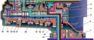
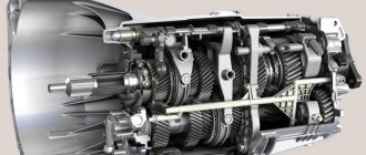
VAZ 2110 gearbox diagram:
| 1 – clutch release bearing; | 18 – driven gear of the second gear of the secondary shaft; |
| 2 – guide sleeve of the clutch release bearing; | 19 – driven gear of the third gear of the secondary shaft; |
| 3 – main gear drive gear; | 20 – synchronizer for 3rd and 4th gears; |
| 4 – roller bearing of the secondary shaft; | 21 – driven gear of the fourth gear of the secondary shaft; |
| 5 – oil sump; | 22 – ball bearing of the secondary shaft; |
| 6 – satellite axis; | 23 – driven gear V of the secondary shaft transmission; |
| 7 – speedometer drive drive gear; | 24 – 5th gear synchronizer; |
| 8 – axle gear; | 25 – secondary shaft; |
| 9 – differential box; | 26 – rear cover of the gearbox housing; |
| 10 – satellite; | 27 – drive gear of 5th gear; |
| 11 – clutch housing; | 28 – ball bearing of the input shaft; |
| 12 – driven gear of the main gear; | 29 – input shaft; |
| 13 – adjusting ring; | 30 – gearbox housing; |
| 14 – tapered roller bearing of the differential; | 31 – roller bearing of the input shaft; |
| 15 – axle shaft seal; | 32 – input shaft oil seal; |
| 16 – driven gear of the 1st gear of the secondary shaft; | 33 – breather. |
| 17 – synchronizer of 1st and 2nd gears; |
The operating scheme is as follows: the input shaft (29) is made in the form of a block of drive gears, which are in constant engagement with the driven gears of all forward gears. The secondary shaft (25) is hollow, with a removable drive gear (3) of the main gear. On the secondary shaft there are driven gears (16, 18, 19, 21, 23) and synchronizers (17, 20, 24) for forward gears. The front bearings (4, 31) of the shafts are roller, the rear bearings (22, 28) are ball. An oil sump (5) is located under the front bearing of the secondary shaft, directing the flow of oil into the secondary shaft and further under the driven gears.
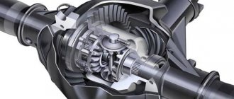
The differential is two-satellite. The preload in the differential bearings is adjusted by selecting the thickness of the ring (13). The driven gear (12) of the main gear is attached to the differential box flange.
selection of differential bearing adjusting ring
Differential bearings must be mounted with a preload of 0.25 mm (for control 0.15-0.35 mm). The tension is ensured by selecting the thickness of the adjusting ring 13 (see Fig. 3-7), installed in the gearbox housing socket under the outer ring of the differential bearing.
Note.
Select the thickness of the adjusting ring when replacing one of the following parts: differential box, differential bearing and clutch or gearbox housings.
Determine the thickness of the adjusting ring using tool 67.7824.9517 in the following sequence: press the outer ring of the tapered roller bearing 3 together with the adjusting ring 4 (Fig. 3-24) into the gearbox housing;
Note.
The installation ring 4 has a constant thickness of 1.25 mm.
Press the outer race of the other differential bearing into the clutch housing. At the same time, be careful not to mix up the outer rings of the differential bearings; install the differential into the gearbox housing and, covering it with the clutch housing, tighten at least three nuts, equidistant from each other, securing the gearbox housing to the clutch housing (tightening torque 24.5 Nm (2.5 kgcm)). Then turn the differential to self-install the bearings 2-3 turns; install support mandrel 2 on the differential box and secure indicator 1 with extension using a universal holder. Install the indicator leg on the support mandrel with a preload of 1 mm, and in this position fix the indicator and set its arrow to zero; move the differential from below and watch the indicator;
WARNING
When measuring the axial movement of the differential, do not rotate it so as not to distort the measurement results.
Using the formula S = A + B + C, calculate the thickness of the adjusting ring of the differential bearings, where: S is the thickness of the adjusting ring; A is the amount of axial movement of the differential; B - the amount of preload of the differential bearings; C is the thickness of the installation ring (constant value). Example.
The indicator reading when moving the differential is 1.00 mm. The preload of the differential bearings is 0.25 mm, the thickness of the mounting ring is 1.25 mm. S = 1.00+ 0.25+ 1.25 = 2.50 mm. After determining the thickness of the adjusting ring, disconnect the clutch housing and gearbox, remove the differential, press out the outer bearing ring from the gearbox housing using a puller 67.7801.9526 and install the selected adjusting ring instead of the adjusting ring 4. Press in the outer ring of the differential bearing using the mandrel 67.7853.9575 and install the differential into the gearbox housing and, covering it with the clutch housing, tighten the nuts securing the gearbox to the clutch housing. Check the moment of resistance to rotation of the differential with a dynamometer 02.7812.9501. To do this, pass the tip of the dynamometer through the hole in the differential box (for the wheel drive shaft) until it wraps around the pinion axis. Turn the dynamometer handle several turns clockwise and use the scale to determine the moment of resistance to turning. It should be: for new bearings 147-343 Ncm (15-35 kgf.cm), for run-in bearings at least 30 Ncm (3 kgf.cm).
Something bad happened and a VAZ 2110 gearbox needed to be repaired. Unit repair is required when:
- It is difficult to switch gears off and on.
- automatic switching off of gears.
- noise occurs when shifting gears.
- transmission oil leak.
The reasons for the breakdown may be different, perhaps the oil was not changed in a timely manner or the mechanism has simply exhausted its resource.
How is a VAZ 2110 gearbox repaired? Do-it-yourself VAZ 2110 gearbox repair, video.
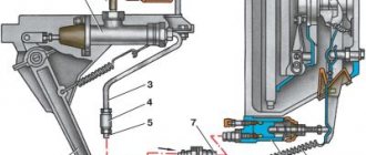
Gear shift drive diagram:
| 1 – gear selection rod lever; | 10 – hinge bushing; |
| 2 – gear selection lever; | 11 – hinge tip; |
| 3 – gearbox housing; | 12 – clamp; |
| 4 – clutch housing; | 13 – protective cover of traction; |
| 5 – gear selection rod; | 14 – gearbox control drive rod; |
| 6 – rod bushing; | 15 – gear shift lever; |
| 7 – rod seal; | 16 – ball joint cage; |
| 8 – protective cover; | 17 – ball joint of the gear shift lever; |
| 9 – hinge body; | 18 – jet thrust. |
The gearbox control drive consists of a gear shift lever (15), a ball joint (17), a rod (14), a gear selection rod (5) and gear selection and shift mechanisms (crumpled “P”).
To prevent spontaneous switching off of the P due to the axial movement of the power unit on its supports when the vehicle is moving, a reaction rod (18) is introduced into the gearbox control drive, one end of which is connected to the power unit, and a clip (16) of the ball joint of the lever (15) is attached to the other end ) switching P.
A lever (1) is attached to the inner end of the rod (5), which acts on the three-year lever (2) of the P selection mechanism. This mechanism is made as a separate unit and is attached to the plane of the clutch housing.
Possible problems and troubleshooting
| Causes of problems | Remedies |
|
|
|
|
|
|
|
|
Gear selection mechanism:
| 1 – gear selection lever (forward); | 6 – reverse fork axis; |
| 2 – guide axis of locking brackets; | 7 – locking bracket; |
| 3 – axis of the gear selection lever; | 8 – reverse fork; |
| 4 – spring; | 9 – gear selection lever (reverse); |
| 5 – retaining ring; | 10 – housing of the gear selection mechanism. |
Two axles are mounted in the housing (10) of the gear selection mechanism. A three-year-old gear selector lever and two locking brackets (7 and 12) are installed on the axis (3). The other axis (2) passes through the holes of the locking brackets, securing them from turning. The gear selector lever arm (1) is used to engage P forward gear, the lever arm (9) is used to engage reverse gear, and the third arm is used by the gear selector rod lever. A fork (8) for engaging reverse gear is installed on the axle (6).
Oil is poured into the gearbox of a VAZ 2110, the level of which should be between the control marks of the oil level indicator.
Like any car, the VAZ 2110 also has a gear shift mechanism. The VAZ gearbox is five-speed, activated by a lever located in the car's interior.
In order to be able to fix problems yourself, you need to understand a little about how exactly the switching mechanism works, which is why there are cases when some speed does not turn on or goes out. And also know how to fix it on your own.
Malfunctions
Every car owner with experience begins to feel a malfunction in the car’s gearbox based on characteristic signs. Most gearbox breakdowns are associated with wear of rubbing parts, because they experience constant significant load while driving. However, such wear rarely reaches a critical state immediately. This is usually a gradual process, which is why a novice driver is always advised to learn to “listen” to the car. The sooner you notice a problem, diagnose it accurately and fix it, the less repair work will need to be done and the less it will cost.
It is recommended to regularly check where the vehicle is parked for stains to monitor leakage of technical fluids.
You can classify signs that indicate breakdowns as follows:
- Noise in manual transmission. This may be a crackling, knocking, rustling, grinding, as well as beating of the gear shift lever. Knocking can occur during different phases of the box's operation. An experienced motorist can even determine from such a rustle which parts are at risk. For example, noise when a car turns into a turn indicates wear on the differential gears.
- Gears are hard to engage. In addition to the wear of parts of the gearbox itself, the malfunction may also lie in the clutch. In addition, there is a risk of deformation of the gearshift control rods. Remember that plastic parts break much more easily than metal parts.
- Spontaneous “dropping out” of the gear while driving. Over time, gear teeth become chipped and worn down, becoming shorter. The slightest vibration disengages them and the transmission “flies out”. In this case, it is also necessary to check the engine mounting.
- A sharp click and loss of smoothness when changing gears. If the clutch is working properly, then the cause of such a problem is most often the failure of the synchronizer blocking ring of the desired gear.
- The box “eats” a lot of oil. Increased oil consumption is primarily a leak. It can occur through a depressurized crankcase, as well as worn oil seals, which are located on almost any hole in the box body.
Malfunctions also include rattling of the gearshift lever. More information can be found here:
Most of these faults cannot be solved in any other way than by replacing worn parts. The gearbox is close to the center of mass of the car and breaks down much less often than the engine or suspension.
Such gear failures cannot be eliminated in any way except by replacing the unit
Therefore, if something happens to it, repairs will definitely be required. In order to find out which wear parts cause noise or interfere with the smooth movement of the lever, you need to remove and disassemble the gearbox.
Checkpoint diagram
The gearbox design is as follows:
- To ensure gear shifting, the gearbox contains a primary shaft consisting of a gear block. They are constantly engaged with the drive gears from the first to the fifth speed (that is, those that are oriented towards driving forward);
- The secondary shaft is equipped with a drive gear for the main transmission, and it also has gear synchronizers that ensure forward movement of the driven gears. There are also bearings plus an oil sump;
- VAZ two-satellite differential, with the driven gear of the main gear attached to the flange of its box;
- the gearbox drive consists of a gear shift knob, a ball joint, a selector rod, a rod, gear selection mechanisms, and gear shifting mechanisms;
- Jet thrust is designed to protect the gearbox from flying out of gear. Its ends are attached to the support and the power unit.
Gear shift drive diagram
Possible problems during operation
The VAZ 2110 gearbox diagram is quite simple, but it still has problems. To avoid having to completely disassemble it, you should pay attention to the following malfunctions:
- uncharacteristic noises and hums during movement and simply in working condition;
- The VAZ 2110 has a light transmission, so tight shifting indicates a problem;
- large play of the lever;
- gears fall out while driving;
- Speeds change with an unpleasant crunching sound.
Repairing a VAZ 2110 gearbox from these problems can be done in a few hours. To do this, you need to know how to properly remove the gearbox on a VAZ 2110, without damaging other important parts. If you do not have enough experience and skills for these actions, then it is better to seek help from specialists.
The gear shift mechanism in the VAZ 2110 gearbox is quite simple and differs little from a standard manual transmission. But, like other cars, it doesn’t like sudden jerks, quick shifts and other issues related to speed, because this car is not initially fast. The VAZ 2110 gearbox adjustment synchronizer is responsible for every incorrect movement and tries to regulate gusts so as not to harm the mechanism.
Disassembling the gearbox 2110 at a service center will allow you to eliminate even minor breakdowns, which later bring a lot of trouble.
If you know that replacing your gearbox in a VAZ 2110 is not difficult, then it is better to do it and then the car will be able to last a much longer time. Remember that timely repair will completely eliminate the possibility of replacing the mechanism.
Adjustment
On a VAZ 2110, it is not so uncommon for the gears to shift poorly or get knocked out. A mechanism for adjusting the speed selection drive is provided specifically for this purpose.
Adjustment may be necessary if:
- the box was recently removed for repairs;
- one of the gears falls out;
- the speeds do not engage well or simply get knocked out when the car is moving.
If you have one of these problems, try making adjustments first. Its sequence:
- Under the bottom of the VAZ 2110, find and slightly loosen the nut on the bolt that tightens the clamp that secures the rod designed to control the gearbox;
- Use a screwdriver to slightly move apart the grooves in the end of the rod and the resulting gap on the clamp itself. This is necessary to ensure easy movement of the rod in relation to the gear selection rod. Place the rod in the neutral position;
- Release the shift knob from the cover in the cabin;
- Align the lever using a special template. This is done like this: install a template in the window of the rear speed lock bracket lining. After this, insert the lever axis stop into the groove of the template, pressing it without unnecessary force in the transverse direction;
- Then adjust the axial play of the rod in the rear direction, and its axial play by turning to the left;
- Install the clamp, not reaching a few millimeters from the end of the rod. Then tighten the clamp thoroughly with the bolt.
Video “The principle of operation of a manual transmission”
This video shows the principle of operation of the manual transmission, which is used in the VAZ 2110 car.
The VAZ 2110 gearbox is still very popular. Despite the fact that these cars have been out of production for several years now, the mechanisms feel great and continue to serve their owners.
You can repair the VAZ 2110 gearbox yourself if you have sufficient experience and all the necessary equipment. The procedure may take a different amount of time, depending on which part has failed. Remember that the VAZ 2110 tolerates repairs calmly and does not require expensive parts and equipment.
CPT diseases
VAZ 2110 owners often complain that the first gear is difficult to engage or crashes.
- often the synchronizer is to blame;
- perhaps the clamp spring has burst, the lever is hanging loose, the speeds are switched on as desired;
- The stem and fork may need replacement.
Another complaint is that second gear is difficult to engage and often gets knocked out.
Here you can suspect the main culprits:
- the second one flies out most often because the gear teeth do not mesh well with the clutch that turns on the speeds;
- The tips of the gear teeth and clutch are already worn out, so the speed is difficult to engage. If you don’t intervene, it will soon fly out;
- as an option, when it knocks out on bumps, the clutch dies.
Sometimes (albeit rarely) when the second one does not turn on well enough and falls out, replacing the retaining spring helps. If the speeds often drop out, some of them are difficult to turn on, which means that half-measures will no longer help - the box needs to be overhauled.
Whether you do it yourself, or go to a service center where they will repair it for you and also adjust the gear shift mechanism, decide for yourself, based on your own experience and skills.
Cross-sectional design of a gearbox on a VAZ 2110
Main parts of the VAZ 2110 gearbox: 1 – rear cover of the gearbox housing, 2 – fifth gear drive gear, 3 – input shaft ball bearing, 4 – fourth gear drive gear of the input shaft, 5 – input shaft, 6 – third gear drive gear input shaft, 7 – gearbox housing, 8 – drive gear of the second gear of the primary shaft, 9 – reverse gear, 10 – intermediate reverse gear, 11 – drive gear of the first gear of the primary shaft, 12 – roller bearing of the input shaft, 13 – oil seal input shaft, 14 – breather, 15 – clutch release bearing, 16 – clutch release bearing clutch guide sleeve, 17 – main drive drive gear, 18 – secondary shaft roller bearing, 19 – oil sump, 20 – pinion axis, 21 – drive drive gear speedometer, 22 – axle gear, 23 – differential box, 24 – satellite, 25 – clutch housing, 26 – oil drain plug, 27 – main drive driven gear, 28 – adjusting ring, 29 – differential tapered roller bearing, 30 – oil seal axle shaft, 31 – driven gear of the first gear of the secondary shaft, 32 – synchronizer of the first and second gears, 33 – driven gear of the second gear of the secondary shaft, 34 – driven gear of the third gear of the secondary shaft, 35 – synchronizer of the third and fourth gears, 36 – driven gear of the fourth transmission of the secondary shaft, 37 – ball bearing of the secondary shaft, 38 – driven gear of the fifth gear of the secondary shaft, 39 – fifth gear synchronizer, 40 – secondary shaft.
Gearbox control drive VAZ 2110
VAZ 2110 backstage diagram: 1 – protective cover of the rod, 2 – gearbox control rod, 3 – gear shift lever, 4 – pin of the spherical gear shift lever, 5 – ball joint cage, 6 – ball joint of the gear shift lever, 7 – buffer , 8 – spring, 9 – reaction rod, 10 – gear selection rod lever, 11 – gear selection lever, 12 – gearbox housing, 13 – clutch housing, 14 – gear selection rod, 15 – rod bushing, 16 – rod seal, 17 – protective cover, 18 – hinge body, 19 – hinge bushing, 20 – hinge tip, 21 – clamp.
The principle of operation of the VAZ 2110 gearbox
The gearbox is mechanical, two-shaft, with five forward gears and one reverse gear, with synchronizers in all forward gears. It is structurally combined with the differential and main gear.
The gearbox housing consists of three parts (cast from aluminum alloy): the clutch housing, the VAZ 2110 gearbox housing and the rear cover of the gearbox housing. During assembly, a gasoline-oil-resistant gasket sealant (for example, KLT-75TM or TB-1215) is applied between them. There is a special magnet in the crankcase socket that retains metal wear products.
The input shaft of the VAZ 2110 is designed as a block of drive gears, which are in constant engagement with the driven gears of all forward gears. The secondary shaft of the VAZ 2110 is hollow (for supplying oil to the driven gears), with a removable drive gear of the main gear. It houses the driven gears and forward gear synchronizers. The front shaft bearings are roller, the rear are ball. The radial clearance in roller bearings should not exceed 0.07 mm, in ball bearings - 0.04 mm. An oil sump is located under the front bearing of the secondary shaft, directing the flow of oil into the shaft.
The differential is two-satellite. The preload in the bearings (0.25 mm) is adjusted by selecting the thickness of the ring installed in the gearbox housing housing under the outer ring of the differential bearing. The main drive driven gear is attached to the differential box flange.
The gearbox control drive consists of a gear shift lever, a ball joint, a rod, a gear selection rod and gear selection and shift mechanisms. TB-1324 thread glue is applied to the screws securing the rod and lever to the gear selector rod before assembly. The lever and hinge mounting screws vary in length, coating and tightening torques. The lever fastening screw is phosphated (dark color), 19.5 mm long, tightened with a torque of 3.4 kgf.m. The hinge fastening screw is cadmium-plated (golden), 24 mm long, tightened with a torque of 1.95 kgf.m. LSC-15 lubricant is placed in the ball joint before assembly.
To prevent the gears from spontaneously switching off due to the axial movement of the power unit when the vehicle is moving, a reaction rod is introduced into the gearbox control drive, one end of which is connected to the power unit, and a ball joint race for the gear shift lever is attached to the other end.
A lever is attached to the inner end of the rod, which acts on the three-arm lever of the gear selection mechanism. This mechanism is made as a separate unit and is attached to the plane of the clutch housing.
The housing of the gear selection mechanism of the VAZ 2110 has two axes. One has a three-arm gear selector lever and two locking brackets. The other axis passes through the holes of the locking brackets, securing them from turning. One arm of the gear selection lever is used to engage forward gears, the other is used to engage reverse gear, and the third arm is used by the gear selection rod lever. A reverse fork is installed on the axle.
The gearbox is filled with TM-5-9p oil at the factory, designed for 75,000 km. The oil level in the VAZ 2110 gearbox should be between the control marks on the oil level indicator.
“>
Oil change intervals
The official manual for the car indicates how often the transmission oil in the box needs to be changed - 60 thousand kilometers. To prevent unit malfunctions, experts recommend adhering to certain rules:
- change the oil in the box in a timely manner;
- pour the required amount of oil into the VAZ 2114 gearbox and monitor its level;
- Use only high-quality lubricant.
The oil volume in the VAZ 2114 gearbox is also indicated in the manual for the car. According to the instructions, the box holds approximately 3.3 liters of lubricant.
When choosing oil for a manual transmission, you need to decide on the packaging of the fluid. It is usually sold in canisters of 1, 3 and 5 liters, but there are also non-standard containers. Also, anyone can buy oil from a barrel for bottling in specialized stores
Therefore, you can get the required amount of oil on favorable terms, but it is important to carefully check the quality of the products. Otherwise, imaginary savings may subsequently lead to serious costs for repair work.
Installation of the backstage from "Kalina"
Replacing the VAZ 2110 gearbox
On a VAZ 2110 you can successfully install a slide from Kalina:
- To do this, it needs to be modified a little.
- The cardan from the new model is 20 mm longer than the original “tenth”.
- Therefore, it needs to be cut, to do this, use a lathe.
- The replacement of the slide must be carried out in the garage from the inspection hole.
- Remove the plastic tunnel from the car interior.
- Also remove the boot.
- Remove the old rocker, unscrew all the fasteners from under the bottom of the car.
- Install a new link and adjust it.
Why is it recommended to install a cardan from the new Kalina? On VAZ-2110 models, universal joints made of less resistant material are installed, so they quickly fail. This causes premature play in the rocker, which usually affects the quality of gear shifting while the vehicle is moving. After purchasing a new link, a visual comparison should be made of the old cardan and the purchased one. The comparison will be entirely in favor of the new acquisition. The Kalina cardan is made of better quality material, it is much more wear-resistant.
Gearbox slides for VAZ 2110
After installing a new link, the lever may rattle. Since this link completely eliminates play, that is, the vibration is transmitted completely to the lever.
Fixing lever rattling
- To do this, install a new ball joint for the lever and install a repair kit.
- The ball joint must be replaced from the inspection hole, since it is easier to change it from under the bottom of the car.
- Install the retaining spring to the gear lever.
It will dampen vibration by holding the lever in the desired position. This will not affect the application of additional forces when turning on the speeds. To get rid of the rattling of the lever, you can install additional plastic washers on the gearbox axle. To do this you will need:
- material - plastic (regular lid for jars);
- open-end wrench No. 10, No. 13;
- scissors;
- Phillips screwdriver;
- flat file, you can use a small flat file.
Features of mechanical devices
Dismantling or removing the device is the first step for those who decide to repair the gearbox themselves. It is advisable to have an assistant nearby, it will be much easier.
First, the battery is removed from the car, then they move on to the starter. Replacing the backstage on your own is carried out in the same way, there are only minor differences. Repairing the secondary shaft requires approximately the same actions. The cable responsible for the clutch must be disconnected from the fork. The device has a special bracket from which the part is pulled out.
Any reference book on gearbox repair at home will tell you about this.
Repairing the gearbox linkage is also not complete without this. First you need to compress the required number of spring-type clamps, after which the part with the block is dismantled. There are several bolts responsible for the connection between the torque rod and the box. They need to be unscrewed using a key with the appropriate parameters. How and when the gearbox drive shaft is repaired is indicated in the VAZ 2110 operating manual.
Gearbox shifter for VAZ 2110.
At the next stage, a major overhaul requires the removal of the wheel drives. The main thing is that there is a plug left there. The ball joint structure, which is located on the left side, is turned away from the fist.
Repair of the gearshift knob is carried out separately, if necessary. The instructions are easy to find.
The ball joints can be left in place, but unscrewing them makes the job faster and easier. The engine, for its part, is equipped with only one mount. Therefore, repairing a lever and other similar processes only require unscrewing one nut at a given moment. Sometimes it is necessary to remove the hose responsible for injection from the stud. The repair manual says that the box itself moves as far back as possible.