Planetary gear is a type of gear used in manual and automatic transmissions. In addition to converting rotation, the planetary gear is capable of summing and distributing power. Knowing about the planetary mechanism: what it is, how it works, by what criteria the gearbox is evaluated, the structure and characteristics of the automatic transmission will become clear. In the event of a breakdown, calculating the transmission will help you choose a reliable and durable mechanism.
Design and principle of operation
A planetary mechanism is a structure of gears moving relative to the center. Wheels of different diameters are located along the central axis:
- small solar with external teeth;
- large crown or epicycle with internal teeth.
The satellites move between the wheels. Their rotation resembles the movement of the planets of the solar system. The mechanical axes of the satellites are connected to a carrier, which rotates about the central axis.
Construction of a simple planetary block:
- 1 epicycle;
- 1 sun wheel;
- 1 carrier.
The planetary mechanism is assembled in cascades of two or more links on one shaft to obtain a wide range of gears. The main kinematic characteristic of a gear transmission is the gear ratio.
The operating principle of the planetary gearbox is to lock one of the main elements and transmit rotation through the drive wheel. To stop the element, brake bands, locking clutches, and bevel gears are used. The gear ratio varies depending on the fastening scheme. It is more convenient to describe the operating principle of a planetary mechanism using an example:
- The crown is blocked.
- The shaft supplies torque to the sun.
- The rotation of the sun causes the planets to roll around with it.
- The carrier becomes a slave, indicating a lower gear.
By controlling the elements of a simple “planetary”, you get different characteristics:
| Broadcast | How does a planetary gearbox work in an automatic transmission? |
| 1 | The sun sends rotation to the carrier, the crown moves in the opposite direction. |
| 2 | The crown applies rotation to the carrier, the sun is fixed. |
| 3 | The leading carrier transmits rotation to the sun. The crown is blocked. |
| 4 | The carrier moves the crown. The sun is fixed. |
| Reverse | The carrier is blocked. The solar wheel rotates, the planets roll around and move the corona in the opposite direction. |
The efficiency η of a simple transmission reaches 0.97.
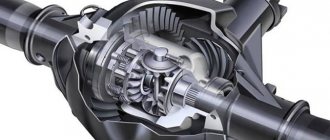
A planetary gear set with one degree of freedom becomes a planetary gear. Two degrees form a differential. The differential adds up the torques on the driven wheel coming from the main drive links.
Read
Adjustment, replacement and why a brake band is needed in an automatic transmission
Gearbox: purpose and principle of operation
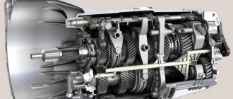
Speaking in dry technical language, the gearbox serves to change the torque transmitted from the engine crankshaft to the drive wheels, to move the car in reverse and to long-term disconnect the engine from the transmission while the car is parked and when it is moving by inertia (coasting).
Now, from the point of view of a beginner, let's figure it out - why do you need a gearbox on a car at all, and why do you need to change gears? Gear shifting is a necessity that arose due to the uneven torque characteristics of the internal combustion engine. Let's compare, for example, an internal combustion engine and an electric motor.
Traction characteristics of internal combustion engines and electric motors
The main difference between a car and an electric traction motor from the point of view of interest to us is the traction characteristics, that is, how power and torque change depending on the speed. The electric motor has quite a lot of torque at low speeds. As it spins up, the torque drops.
For a transport vehicle, this characteristic is most favorable: when starting and accelerating, when you have to overcome significant inertial forces, it is desirable to have as much torque as possible. And to maintain uniform motion, much less torque is needed.
Note that the power of the electric motor at any speed can remain close to maximum and is used almost completely in all modes, that is, it is perfectly adapted to road operating conditions.
With an internal combustion engine, everything is different: its power at low speeds is significantly reduced, and the amount of torque within the operating speed limits generally changes little.
The graph shows (Fig. A) that if the resistance to movement has increased and the engine speed begins to fall, then for the electric motor this is accompanied by a significant (several times) increase in torque; In a car engine, the torque first increases a little, and then decreases - the engine stalls.
As you can see, the traction characteristics of the internal combustion engine are completely unsatisfactory. But a power plant with such a motor is still superior to an electric motor in its lightness, efficiency and other qualities. Therefore, the designers had to come to terms with the shortcomings of the internal combustion engine and, to overcome them, install a gearbox on the car that changes the gear ratio
between the engine and the drive wheels and, accordingly, the torque on them. Figure B shows how, with the help of a stepped gearbox, the traction characteristic of an internal combustion engine tries to approach the ideal hyperbola.
Gear transmissions
What is a gear ratio? Let's go a little deeper into the mechanics. In a gear train consisting of two gears, one driving and the other driven, their relative sizes determine the rotation speed and torque. The ratio of the number of teeth of the driven gear to the number of teeth of the drive gear is called the gear ratio.
If the drive gear is smaller than the driven gear, then the rotation speed of the driven gear will be less, and the torque will be greater, and vice versa. That is, while gaining in strength, we lose in speed, and, on the contrary, while gaining in speed, we lose in strength. If several pairs of gears are involved in the transmission, then the total gear ratio is obtained by multiplying the gear ratios of all pairs of gears participating in the transmission.
To obtain varying amounts of torque required for vehicle operation in different conditions, the gearbox has several pairs of gears with different gear ratios. If an intermediate gear is placed between the drive and driven gears, the driven gear will change the direction of rotation to the opposite (we get reverse gear).
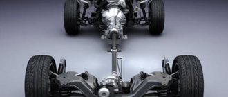
Thus, any gearbox, be it manual, automatic or CVT, serves to ensure optimal engine operation in various driving conditions by changing the gear ratio.
In any gearbox there are higher and lower stages (gears).
When starting from a stop, accelerating, driving at low speeds and off-road, high torque is required, which is achieved at medium-high speeds, but there is no need to develop high speeds. To move in this mode, the lower stages of the gearbox (usually the first to third), which have the highest gear ratio, are used; in this case, even at high engine speeds the car will drive slowly.
For uniform movement at high speed, it is necessary to ensure a high rotation speed of the wheels, maintaining engine speed in the optimal range. For this purpose, higher gears (from fourth and higher) are used, which have significantly lower gear ratios compared to lower ones.
In this case, the car will drive quite quickly at the same engine speed until the maximum operating speed of the engine is reached.
However, in higher gears, the car cannot move at low speed, much less move away, since the engine will not be able to develop the torque necessary to move the car and will stall.
Types of planetary gears
Based on the number of stages, planetary mechanisms are divided into:
- single row;
- multi-row.
The planetary gear consisting of one sun gear, single-rimmed satellites, carrier and epicycle will be single-row. Replacing satellites with double-crown ones complicates the design, making it double-row.
The multi-stage planetary gearbox is a series of single-row units. This scheme allows you to sum up the gear ratios and get larger values. 4-speed automatic transmissions consist of two-row planetary designs, 8-speed automatic transmissions consist of four-row ones.
Automatic transmissions use circuits named after the inventors:
- The Wilson mechanism is a three-row design in which the crown of the first, carrier of the second and crown of the third rows are connected. Number of gears: 5 direct and 1 reverse.
- The Lepeletier mechanism consists of 3 coaxially located simple planetary gears. Number of gears: 6 direct and 1 reverse.
- Simpson's scheme - 2 gearboxes with a common sun gear. The second row carrier is equipped with a brake. The crown of the first row and the sun are rigidly connected to the drive shaft through two locking couplings. The mechanism implements the following modes: neutral; 1,2,3 gears; reverse.
According to the type of gear structures, planetary gearboxes are divided into:
- cylindrical;
- conical;
- wave;
- worm-type
Different types are used to transmit torque between shafts located parallel or at an angle. And also in mechanisms requiring low or high kinematic characteristics.
How does a planetary gearbox work?
The operation of a planetary gear of the simplest design in the case of a stopped epicycle occurs as follows. The sun gear is driven into rotation. Together with it, the satellites linked to it begin to rotate. As the planet gears turn, they roll over the sun gear and around the epicycle. Thus, they move around the sun gear, causing the carrier on which the satellite axes are attached to rotate.
The design of the planetary mechanism allows you to work not only with a stopped epicycle, using the sun gear as an input, and the carrier as an output. Of the three listed elements: sun gear - carrier - epicycle, any two can be used as an input or output, and the remaining third can be braked. The planetary gear with such methods of inclusion will still work, only the gear ratio will change both in magnitude and sign. In total, six similar methods of inclusion are possible, but the one described above is most widely used: input - sun gear, output - carrier, epicycle - stationary. This inclusion has the largest gear ratio of all available methods.
If both the sun gear and the carrier and the epicycle rotate in the planetary mechanism, then the mechanism begins to work as a differential, allowing the addition of angular velocities at different inputs or their decomposition of the angular velocity into two different outputs.
Characteristics of the main varieties of this device
Various types of gears are used in the design of the planetary gear set of automatic transmissions. There are three main most common ones: cylindrical, conical and wave.
Cylindrical
Gear mechanisms transmit torque between parallel shafts. The design of a cylindrical gear includes two or more pairs of wheels. The shape of the gear teeth can be straight, oblique or chevron. The cylindrical circuit is simple to manufacture and operate. Used in gearboxes, final drives, drives. The gear ratio is limited by the size of the mechanism: for one wheel pair it reaches 12. Efficiency is 95%.
Read
How to change from a manual transmission to an automatic transmission
Conical
Wheels in a conical design convert and transmit rotation between shafts located at an angle of 90 to 170 degrees. The teeth are loaded unevenly, which reduces their ultimate torque and strength. The presence of forces on the axes complicates the design of the supports. For smooth connection and greater endurance, a circular tooth shape is used.
The production of bevel gears requires high precision and is therefore expensive. Angular structures are used in gearboxes, valves, and milling machines. The gear ratio of bevel mechanisms for medium-duty equipment does not exceed 7. Efficiency is 98%.
Wave
In wave transmission there are no sun and planetary gears. Inside the crown wheel there is a flexible oval-shaped gear. The carrier acts as a wave generator, and looks like an oval cam on a special bearing.
A flexible steel or plastic wheel is deformed under the action of the carrier. Along the major geometric axis, the teeth engage with the crown to the entire working height; along the minor axis there is no engagement. The movement is transmitted by a wave created by a flexible gear wheel.
In wave mechanisms, the efficiency increases along with the gear ratio exceeding 300. Wave transmission does not work in circuits with a kinematic characteristic below 20. The gearbox produces 85% efficiency, the multiplier - 65%. The design is used in industrial robots, manipulators, aviation and space technology.
Planetary gears
General information about planetary gears
Planetary gears are gears that have gears with moving axes.
A distinctive feature of mechanisms that include a planetary gear (or gears) is the presence of two or more degrees of freedom. In this case, the angular velocity of any transmission link is determined by the angular velocities of the remaining links. The most widely used is a simple single planetary gear (Fig. 1), which consists of a central wheel 1 with external teeth, a fixed central wheel 3 with internal teeth; satellites 2 - wheels with external teeth, meshing simultaneously with wheels 1 and 3 (in Fig. 1, the number of satellites c = 3), and a carrier H, on which the axes of the satellites are fixed. The carrier is connected to a low-speed shaft. In a planetary gear, one wheel is stationary (connected to the housing). Typically, the outer center wheel with the inner teeth is called the crown wheel (ring gear or epicycle), and the inner wheel with the outer teeth is called the sun wheel (sun gear or sun).
When wheel 3 is stationary, the rotation of wheel 1 causes rotation of the satellites 2 relative to their own axes, and rolling the satellites along wheel 3 moves their axes and rotates the carrier H. The satellites thus rotate relative to the carrier and together with the carrier around the central axis, p. e. they make a movement similar to the movement of the planets. That is why such transmissions are called planetary.
When wheel 3 is stationary, motion is most often transmitted from wheel 1 to carrier H; motion can be transmitted from carrier H to wheel 1.
In planetary gears, not only cylindrical, but also bevel gears with straight or oblique teeth are used.
If all the links in a planetary gear are made movable, i.e. both wheels and the carrier, then such a gear is called differential. Using a differential mechanism, you can sum up the movement of two links on one or decompose the movement of one link onto two others. For example, in the differential of the rear axle of a car, the movement from the carrier H is transmitted simultaneously to wheels 1 and 3, which allows one wheel to rotate faster than the other when turning.
Types of planetary gears
There are many different types and designs of planetary gears. The most widely used in mechanical engineering is a single-row planetary gear, the diagram of which is shown in Figure 1. This gear is structurally simple and has small dimensions. Finds application in power and auxiliary drives. Planetary gear efficiency η = 0.96…0.98 at gear ratios u = 3…8.
Planetary mechanisms, which contain one or more planetary gears, are divided into single-row, double-row and multi-row. Each set of central gears and satellites rotating in the same plane forms the so-called planetary gear. A simple planetary mechanism with a set of single-crown satellites is single-row. Simple planetary mechanisms with double-crown satellites are double-row. Complex planetary mechanisms can be two, three, four or even five rows.
To obtain large gear ratios, multi-stage planetary gears are used in power drives. In Fig. 2, and the planetary gear is made up of two series-connected single-row planetary gears. In this case, the total gear ratio u = u1×u2 ≤ 64, and the efficiency is η = η1×η2 = 0.92…0.96.
Figure 2, b shows a diagram of a planetary gear with a double-row (double-crown) satellite, for which, when transmitting motion from wheel 1 to the carrier H at n4 =, the gear ratio is determined from the dependencies:
In this transmission u = 3...19 with efficiency η = 0.95...0.97.
As mentioned above, planetary gears, in which all the links are movable, are called differential or simply differentials.
Inevitable manufacturing errors lead to uneven load distribution between the satellites. To equalize the load in gears with three satellites, one of the central wheels is self-aligning in the radial direction (without radial supports). For self-installation of satellites on a fixed central wheel, spherical rolling bearings are used. High demands are placed on the strength and rigidity of the carrier, while its weight should be minimal. Usually carriers are made cast or welded.
Advantages and disadvantages of planetary gears
The main advantages of planetary gears are:
- small dimensions and weight due to power transmission through several streams, numerically equal to the number of satellites. In this case, the load in each gear is reduced several times;
- ease of arrangement in machines due to the alignment of the drive and driven shafts;
- operation with less noise than conventional gears, due to the smaller size of the wheels and the closure of forces in the mechanism. With a symmetrical arrangement of the satellites, the forces in the transmission are mutually balanced;
- low loads on shafts and supports, which simplifies the design of supports and reduces losses in them;
- the possibility of obtaining large gear ratios with a small number of gears and small transmission dimensions.
Planetary gears are not without their disadvantages:
- increased requirements for the accuracy of manufacturing and installation of transmissions;
- more parts, including bearings, and more complex assembly.
Application area of planetary gears
Planetary gears are used as gearboxes in power transmissions and devices, in gearboxes of cars and other self-propelled equipment, while the gear ratio of such a gearbox can be changed by alternately braking various links (for example, the carrier or one of the wheels), in differentials of cars, tractors, etc. . P.
Advantages and disadvantages of planetary gears
Planetary gears outperform simple gear mechanisms of similar power due to their compact size and 2-3 times less weight. Using several planetary gears, 80% tooth engagement is achieved. The load capacity of the mechanism increases, and the pressure on each tooth decreases.
The kinematic characteristic of the planetary mechanism reaches 1000 with a small number of gears without the use of multi-row structures. In addition to the transmission, the planetary circuit is capable of operating as a differential.
Due to the alignment of the shafts of the planetary mechanism, it is easier to assemble machines than with other gearboxes.
The use of a planetary gear set in an automatic transmission reduces the noise level in the vehicle interior. A balanced system has high vibration resistance due to vibration damping. Accordingly, body vibration is reduced.
Disadvantages of the planetary mechanism:
- complex production and high precision assembly;
- bearings are installed in the satellites, which fail faster than the gear;
- As the gear ratio increases, the efficiency drops, so the design has to be complicated.
Read
What is the difference between rights to an automatic and rights to a manual?
Planetary gear ratio
The gear ratio is the ratio of the frequency of the drive shaft of a planetary gear to the frequency of the driven one. It is not possible to determine its value visually. The mechanism is driven in different ways, which means the gear ratio is different in each case.
To calculate the gear ratio of a planetary gearbox, the number of teeth and the fastening system are taken into account. Let's say the sun gear has 24 teeth, the pinion has 12, and the crown has 48. The carrier is fixed. The sun becomes the leader.
The satellites will begin to rotate at the speed transmitted by the sun gear. The gear ratio is: -24/12 or -2. The result means that the planets rotate in the opposite direction from the sun with an angular velocity of 2 revolutions. The satellites roll around the crown and force it to turn 12/48 or ¼ of a turn. Internal wheels rotate in the same direction, so the number is positive.
The total gear ratio is equal to the ratio of the number of teeth of the drive wheel to the number of teeth of the driven wheel: -24/48 or -1/2 of a revolution is made by the crown relative to the sun with the carrier fixed.
If the carrier becomes driven with the leading sun, then the gear ratio is: (1+48/24) or 3. This is the largest number that the system can offer. The smallest ratio is obtained when the crown is fixed and torque is applied to the carrier: (1+/(1+48/24)) or 1/3.
Gear ratios of a simple planetary scheme: 1.25 - 8, multi-stage: 30 - 1000. As the kinematic characteristics increase, the efficiency decreases.
Selection of numbers of teeth of planetary gears
The number of wheel teeth is selected at the first stage of calculating the planetary scheme according to a predetermined gear ratio. The peculiarity of designing a planetary gear set is to comply with the requirements of proper assembly, alignment and proximity of the mechanism:
- the teeth of the satellites must coincide with the depressions of the sun and the epicycle;
- The planets should not touch each other with their teeth. In practice, more than 6 satellites are not used due to difficulties in uniformly distributing the load;
- The axles of the carrier, sun and crown wheels must coincide.
The basic ratio for selecting transmission teeth through the gear ratio looks like this:
i = 1+Zcorona/Zsun,
where i is the gear ratio;
Read
Typical problems and repairs of automatic transmission f4a42
Zn is the number of teeth.
The coaxial condition is observed when the interaxial distances of the sun wheel, crown and carrier are equal. For a simple planetary gear train, the center distances between the central wheels and satellites are checked. Equality must satisfy the formula:
Zcorona=Zsun+2×Zsatellite.
In order for there to be a gap between the planets, the sum of the radii of adjacent gears should not exceed the axial distance between them. The condition of proximity to the sun wheel is checked using the formula:
sin (π/c)> (Zsatellite+2)/(Zsun+Zsatellite),
where c is the number of satellites.
Planetary wheels are placed evenly if the ratio of crown and sun teeth to the number of satellites is integer:
Zsun/s = Z;
Zcorona/s = Z,
where Z is an integer.
Strength calculation of planetary gears
Strength calculations of planetary gears are carried out as for cylindrical gears. Calculate each link:
- external - between the sun and planetary wheels;
- internal - between the planets and the crown.
If the wheels are made of the same material, and the meshing forces are equal, the least strong connection is calculated - the external one.
The calculation algorithm is as follows:
- Select a gearbox circuit.
- The initial data is determined: gear ratio i, torque Tout and output shaft speed Uout.
- The number of teeth is selected by checking the assembly conditions and the proximity of the planetary gears.
- The angular speeds of the wheels are calculated.
- Calculate the efficiency and moments of the output shafts.
- Calculate the adhesion strength.
When calculating the moment, the number of planetary wheels and the uneven loading of their teeth are taken into account. Enter a correction factor η =1.5...2 if there are no leveling measures:
- increased manufacturing accuracy;
- radial mobility of the sun, corona or carrier;
- use of elastic elements.
The calculation of gears is carried out according to two criteria:
- contact strength, i.e. endurance of working surfaces of teeth under load;
- bending stress, fatigue fracture.
Calculation of contact strength comes down to checking the condition that the stress σн does not exceed the permissible value. Calculations are carried out using the Hertz formula for cylindrical surfaces, adding clarifying coefficients. As a result, the value of the center distance is obtained - the main geometric characteristic of the gear drive:
d=K×η×∛ (T×Kн(i±1))/(Ψ×i×[σн]^2),
where K is the auxiliary coefficient for spur gears, MPa;
η—unevenness coefficient;
T — torque, N×mm;
Kn - load factor;
Read
Technical characteristics of automatic transmissions, types and their differences from each other
Ψ — wheel width coefficient equal to 0.75;
i—gear ratio;
[σн] - permissible contact stress, MPa. Determined by the durability coefficient and endurance limit.
After determining the transmission geometry, the strength condition is checked:
σн= {310/(d×i)}×√ (T×Kн(i+1)^3)/(Ψ×d) ≤ [σн]
When calculating bending, the condition is assumed that the entire load is transferred to one pair of teeth and applied to its top. The design voltage should not exceed the permissible:
σf= (M/W) – (F/(b×s) ≤ [σf],
where M is the bending moment;
W is the axial moment of resistance;
F—compression force;
b, s - dimensions of the tooth in section;
[σf] is the permissible bending stress. Depends on the endurance limit, roughness, and manufacturing errors of the teeth.
Typical faults: when is automatic transmission gearbox repair required?
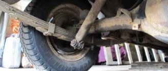
The service life of the planetary mechanism directly depends on the operating style of the vehicle and the quality of maintenance. Most often, premature failure of the planetary gears occurs on crossovers or SUVs, which often travel off-road.
Typical malfunctions of a planetary gearbox include:
- Wear of gear teeth or differential elements.
- Development of splines or twisting of axle shafts.
- Bearing wear.
- Deformation of the gearbox housing or leakage of working fluid.
As a rule, all of the listed malfunctions have a complex factor of origin and arise as a result of the natural wear and tear of the units during high mileage of the transmission, or as a result of aggressive operation of the vehicle. Most often, the need for premature repair of a planetary mechanism arises due to systematic overheating of the transmission, prolonged lack of maintenance, or the use of low-quality or unsuitable oil.
The most common signs of planetary gear malfunction:
- Increased vibration load of the body when accelerating.
- Extraneous sounds when the vehicle is operating in the gearbox area.
- Uneven rotation or runout of the output shaft.
Note! When the first signs of a malfunction appear, it is recommended to immediately contact a service center for diagnostics or troubleshooting. Timely identification of the problem allows the malfunction to be eliminated at the local level, which significantly reduces the cost of repairs and increases the service life of the transmission.
Tips for selecting a planetary gearbox
Before choosing a planetary gearbox, an accurate calculation of the load and operating modes of the mechanism is carried out. Determine the type of transmission, axial loads, temperature range and standard sizes of the gearbox. For heavy special equipment that requires high torque at low speeds, a gearbox with a high gear ratio is chosen.
To reduce the angular speed without reducing the torque, a drive with an electric motor and gearbox is used. When choosing a gear motor, consider:
- operational load;
- output shaft torque;
- rotation speed of input and output shafts;
- electric motor power;
- installation execution.
The difference between a planetary gearbox and other gearboxes
A planetary gearbox has a small diameter when comparing gearboxes of different types designed for the same rated torque. At the same time, the axial length of such planetary gearboxes is usually greater than that of other types of gearboxes.
In standard designs of planetary gearboxes, a wide range of gear ratios is available (for example, up to six thousand in the case of maxon motor planetary gearboxes) in contrast, for example, with wave gearboxes (from 30 to 160 in standard models).
Among planetary gearboxes, you can find models with a wide variety of backlash: from a few degrees for standard models to especially low-backlash gearboxes of a special design (for example, Harmonic Drive planetary gearboxes). On the one hand, this allows them to be more accurate than common models of in-line gearboxes, on the other hand, they do not achieve the accuracy of wave gearboxes.
Application area of planetary gears
The planetary diagram is used in:
- gearboxes;
- automatic and manual transmissions;
- in aircraft drives;
- differentials of cars, devices;
- driving axles of heavy equipment;
- kinematic diagrams of metal-cutting machines.
A planetary gearbox is used in units with variable gear ratios, braking the carrier. In tracked vehicles, the elements in the planetary mechanism do not block for the addition of power flows.
How many satellites should there be?
Compared to a conventional gear, there are more teeth in the planetary gear, and all of them are involved in moving power. With an increase in the number of satellites, the load on each of them decreases; accordingly, it is possible to reduce their diameter and width (material intensity of production) while maintaining the strength characteristics of the planetary gearbox device. Power dissipation is accompanied by reduced tooth wear, as well as increased torsional rigidity of the drive.
Planetary gearboxes usually use three (less often, four) satellites. As their number increases, the requirements for precision in the execution of parts also increase. Thus, the displacement of one of the satellite axes leads to an uneven distribution of transmitted power. This negatively affects the service life of teeth and bearings.