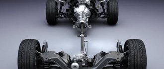
Starter and its functions
A car starter is a small 4-band electric motor that provides primary rotation of the crankshaft. This is necessary in order to ensure the necessary rotation speed to start the internal combustion engine. As a rule, to start a medium-sized gasoline engine, it is necessary to have a starter that has an average of 3 kW of energy. The starter is a DC motor and supplies energy from the battery. Taking voltage from the battery, the electric motor increases its power with the help of 4 brushes, which are an integral part of any car starter.
Among the large number of similar electromagnetic motors, there are only 2 main types: starters with and without gearboxes. With gearbox
Many experts advise using a starter with a gearbox. This is due to the fact that such a device has a reduced current requirement for efficient operation. Such devices will ensure torsion of the crankshaft even when the battery charge is low. Also, one of the most important advantages of such a device is the presence of permanent magnets, which reduce problems with the stator winding to a minimum. On the other hand, if such a device is used for a long time, there is a possibility of the rotating gear breaking. But this, as a rule, leads to a factory defect or simply poor quality production.
Starters that do not have a gearbox have a direct direct effect on gear rotation. In this situation, car owners who have gearless starters benefit from the fact that such devices have a simpler design and are easy to repair (read about repairing a starter yourself). It is also worth noting that after current is supplied to the electromagnetic switch, instantaneous engagement of the gear with the flywheel occurs. This allows for very fast ignition. It is worth noting that such starters have high endurance, and the likelihood of breakdown due to exposure to electricity is minimized. But devices without a gearbox are likely to perform poorly at low temperatures. Principles of operation of a starter with a gearbox
When current is supplied from the car's battery, driven by closing the ignition, to the gear starter, the process of supplying current to the starter armature through the gearbox occurs, which increases the power of the passing voltage several times. Next, torque is transmitted from the armature to the gear. All this also happens with the help of a gearbox, which is equipped with constantly working magnets, and special brushes that are capable of generating greater resistance than the brushes of a conventional starter ensure its constant and efficient operation.
VAZ 2110 starter diagram (5702.3708) 1 – drive shaft; 20 – contact bolts; 2 – front cover bushing; 21 – output of “positive” brushes; 3 – restrictive ring; 22 – bracket; 4 – gear with the inner ring of the overrunning clutch; 23 – brush holder; 5 – overrunning clutch roller; 24 – “positive” brush; 6 – drive shaft support with liner; 25 – armature shaft; 7 – planetary gear axis; 26 – tie rod; 8 – gasket; 27 – back cover with bushing; 9 – lever bracket; 28 – collector; 10 – drive lever; 29 – body; 11 – front cover; 30 – permanent magnet; 12 – relay anchor; 31 – armature core; 13 – holding winding; 32 – armature shaft support with liner; 14 – retractor winding; 33 – planetary gear; 15 – traction relay; 34 – central (drive) gear; 16 – traction relay rod; 35 – carrier; 17 – traction relay core; 36 – gear with internal teeth; 18 – contact plate; 37 – layering ring; 19 – traction relay cover; 38 – hub with the outer ring of the overrunning clutch.
What does the starter consist of?
The main elements that make up the VAZ-2110 starter, the price of which is 2300-2500 rubles, were discussed above. But it also contains a number of parts that affect the performance of the device. The stator winding, located on the stationary part of the device, is necessary to generate an electromagnetic field with the help of which movement is created. But it cannot be created without a counteracting field that forms around the rotor winding.
Consequently, the engine rotor also has a winding, which is powered from the on-board network through a brush assembly. This is the most vulnerable unit, since the brushes are made of graphite. Although it is durable, you should not forget that it constantly rubs against the slats, between which there is a small gap. This results in significant wear, and its result is loss of contact between the starter power input and the rotor lamellas. In the back cover there is a bronze bushing, which is used to center the rotor and power it from the battery negative.
Useful tips
- Before removing the starter, you need to make sure it is faulty. First of all, you need to check the reliability of the terminals on the battery. Oxidized terminals should be cleaned of deposits and re-secured. The reason for the failure may also be poor weight of the engine and the body. You should also check whether the solenoid relay wire has come loose from the connector and whether the positive terminal nut on the starter is tightly tightened;
- When removing a part, you can disconnect the positive wire of the terminal last. In this version, it is more convenient to unscrew the nut of the positive wire. By pulling the starter closer to you, it will be easier to get to the desired nut;
- You need to install the solenoid relay wire in place until it stops. The connector must be fixed, and in this case the wire will not fly off during movement due to shaking;
- Do not forget to first remove the terminals from the battery and turn off the ignition - this will save you from additional problems.
That’s basically all that can be said about how to change the starter on a VAZ 2114.
Solenoid relay
If the VAZ-2110 starter does not turn, then you need to look for the reason for this behavior. And there may be several of them, among the first is a breakdown of the traction relay. It is installed directly on the starter housing and has two functions: it supplies power from the battery positive to the windings, and also moves the bendix along the rotor axis, connecting its teeth to the flywheel crown. Consequently, the crankshaft rotates from the electric motor.
A lot of troubles can happen with the solenoid relay. For example, often its winding simply burns out. Consequently, the traction relay armature does not move and the starter does not turn on. The second, no less common breakdown is contamination of the power contacts. When switching a high current, the copper plates are destroyed, they become covered with soot, causing contact to be lost. Therefore, the retractor will click, but the starter will not turn over.
The starter of VAZ 2101, 2102, 2103, 2104, 2105, 2106, 2107 does not start
What signs indicate that the starter needs to be repaired or is time to be replaced? Why does the starter sometimes not start?
These questions have their own answers:
- The relay functions without problems. However, the anchor does not respond or makes slow rotational movements. Solution ! As a rule, this is due to burning of the collector. It is also necessary to pay attention to the winding. It must be complete. It is also possible that the relay fastening elements are loose, there is a short circuit in the commutator, the brushes are stuck or have become completely unsuitable for further use. However, the reason may lie in a discharged battery.
- The starter responds, but the armature relays do not function. Solution ! Often the whole point is that the anchor is stuck. In this case, it is worth checking how the tips are fixed. Is there a short to ground and what is the condition of the wiring?
- The armature rotates, but problems arise with the crankshaft. Solution ! It's worth checking the buffer spring. Most likely it's broken. Some components of the coupling may be damaged.
- Powerful noises are heard. This is often the result of damaged bushings and gears.
- In turn, the starter turns, but does not start. You need to take a closer look at the return spring. The device may also be skewed. It is also possible that the relay and drive handle are jammed.
Connection diagram
The starter is connected to the on-board network of the VAZ-2110 car according to the standard scheme. It is working and tested, does not require any intervention. The ignition switch has two contacts that close when the key is turned to the extreme position. Now there is no need to talk about the fact that power is supplied to the ECU, fuel pump and other elements of the car. We are talking exclusively about the starter, so only its operation needs to be considered.
So, the contacts closed when the key was turned to the extreme position, and power was supplied to the electromagnetic relay. It is installed under the dashboard. Its switching terminals are supplied with the positive terminal from the battery through a fuse. The voltage is removed from it and supplied to the winding of the traction relay of the VAZ-2110 starter. The result of this is that the armature retracts, moves the bendix and closes the power contacts. The latter are connected as follows: one directly to the battery positive, and the second to the starter power wire.
VAZ2107 fuse and relay diagram
The electrical wiring of the machine is protected by fuses, which are mainly installed in the central and additional units, located at the bottom of the instrument panel on the left side next to the steering column. The circuit from the battery to the terminals and connections is closed when the car ignition is turned on.
F1(16A) Klaxon, lamp socket, cigarette lighter, brake lamps, clock and interior lights (plafonds) F2(8A) Windshield wiper relay, heater and wiper motors, windshield washer F3(8A) Left headlight high beam and warning lamp on high beam F4(8A) High beam of the right headlight F5(8A) Low beam fuse of the left headlight F6(8A) Low beam of the right headlight and rear fog lamp F7(8A) This fuse in the VAZ 2106 block is responsible for the side light (left sidelight, right rear light), trunk light, license plate light right light bulb, instrument lighting lamps and cigarette lighter light F8(8A) Side light (right sidelight, left rear light), license plate light left light bulb, engine compartment lamp and side light warning light F9(8A) Oil pressure gauge with warning lamp, coolant temperature and fuel level indicator, battery charge warning lamp, direction indicators, carburetor choke indicator, rear window heating F10(8A) Voltage regulator and generator excitation winding F11(8A) Reserve F12(8 ) Reserve F13(8A) Reserve F14(16A) rear window heating F15(16A) Cooling system fan electric motor F16(8A) Turn indicators in hazard warning mode
Owners of 2106 should be aware that the old design of fuses has long become obsolete, since each time they operate they overheat, which affects the density of the cells. Lack of tight contact between the fuse and the connectors leads to their burning. Therefore, replacement of the fuse blocks is necessary. To avoid unnecessary problems with the electrical wiring, you should inspect the safety devices every six months. If the contact part burns, it is necessary to replace the fuses and clean the sockets. Today, many VAZ 2106 owners are modernizing classic blocks, replacing them with modern blade fuses.
Replacing the starter on the “ten”
On fuel-injected cars this procedure will be slightly problematic. The reason for this is the air filter, which is located in the engine compartment above the clutch housing. Changing the VAZ-2110 starter solenoid relay will also be problematic. There is not enough space, and if you remove the filter, it is not a fact that you will be able to put it back in place. The rubber bands on which it is attached are so inconvenient that when installing them into the holes on the brackets, you can not only cut them, but also get injured.
Article number and approximate price for the original VAZ 2114 starter
There are two main types of starters used on VAZ 2114 cars. With a carburetor engine, a unit with the factory index 29.3708 is used. Its cost is from 3600 rubles.
On VAZ 2114 cars that have an injector, a starter 5712.3708 is used. It is distinguished by the presence of a planetary gearbox. The presence of a gear in the design made it possible to increase engine speed. Therefore, planetary starters have gained great popularity compared to those previously discussed. At the same time, carburetor VAZ 2114 car owners, when replacing a starter, give preference to units with a planetary gearbox. The price of a new such product starts from 2200 rubles.
In retail sales, original starters are found with article numbers 2108370801006 and 21130370801000. They are interchangeable, but it is recommended to choose a unit with a planetary gear, regardless of the type of vehicle power unit.
How to repair a starter
To carry out repairs, you will need to disassemble the device completely, literally piece by piece. At the same time, the traction relay, which drives the starter on the VAZ-2110, is generally checked and serviced separately. New models are not subject to repair; they are enclosed in a solid body. But if you look at its cost, it turns out that repairs will cost a small amount. When you disassemble the starter, the first thing you will need to do is install new brushes. If the old ones are less than 12 mm long, then they have already become unusable.
Cleaning the slats is also impossible without it. First, clean the gaps between adjacent contacts from dirt, then arm yourself with polishing paste and rub the metal surface. Upon completion of this procedure, rinse with solvent. You should not use sandpaper, as it will make the surface of the lamellas abrasive, resulting in rapid wear of the starter brushes. And at the last stage you replace both bushings. One is located in the rear cover, and the second is located in the clutch housing. When making repairs, replace both, otherwise the rotor alignment will be disrupted. And there will be no contact between the battery negative and the rotor. As a result, you will get that the VAZ-2110 starter simply does not turn.
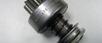
Starter 5712.3708 assembled
1 – armature shaft; 2 – “plus” brush; 3 – brush holder; 4 – bracket; 5 – contact bolts; 6 – traction relay; 7 – contact plate; 8 – traction relay core; 9 – traction relay rod; 10 – relay holding winding; 11 – relay pull-in coil; 12 – traction relay anchor; 13 – drive side cover; 14 – drive lever; 15 – lever bracket; 16 – gasket; 17 – planetary gear axis; 18 – drive shaft support with liner; 19 – overrunning clutch; 20 – drive gear; 21 – restrictor ring for gear travel; 22 – drive shaft; 23 – drive ring; 24 – gear with internal teeth; 25 – carrier; 26 – central (drive) gear; 27 – satellite; 28 – armature shaft support with liner; 29 – armature core; 30 – stator pole (permanent magnet); 31 – collector; 32 – back cover with bushing.
Electrical diagram of VAZ-2106 (old)
General diagram of the electrical equipment of VAZ 2106 / 21061 / 21063 / 21065 produced in 1976 - 1987.
1 – front lights; 2 – side direction indicators; 3 – battery; 4 – battery charge indicator relay; 5 – relay for turning on low beam headlights; 6 – relay for turning on the high beam headlights; 7 – starter; 8 – generator; 9 – external headlights; 10 – internal headlights; 11 – sound signals; 12 – electric motor of the engine cooling system fan; 13 – fan motor activation sensor; 14 – ignition coil; 15 – ignition distributor; 16 – spark plugs; 17 – carburetor solenoid valve; 18 – coolant temperature indicator sensor; 19 – engine compartment lamp; 20 – reverse light switch; 21 – oil pressure indicator sensor; 22 – sensor for low oil pressure indicator; 23 – indicator sensor for insufficient brake fluid level; 24 – windshield wiper gearmotor; 25 – windshield washer electric motor; 26 – relay for turning on sound signals; 27 – relay for turning on the fan motor; 28 – voltage regulator; 29 – windshield wiper relay; 30 – additional fuse block; 31 – main fuse block; 32 – relay-breaker for alarm and direction indicators; 33 – brake signal switch; 34 – plug socket for a portable lamp; 35 – heater electric motor; 36 – additional resistor of the heater electric motor; 37 – hours; 38 – heater motor switch; 39 – glove box lighting lamp; 40 – cigarette lighter; 41 – alarm switch; 42 – instrument lighting switch; 43 – warning lamp for insufficient brake fluid level; 44 – three-lever switch; 45 – ignition switch; 46 – rear fog lamp switch*; 47 – external lighting switch; 48 – lamp switches located in the front door pillars; 49 – switches for warning lights of open front doors; 50 – alarm lights for open front doors; 51 – lamp switches located in the rear door pillars; 52 – parking brake warning switch; 53 – interior lamps; 54 – fuel level indicator with reserve indicator; 55 – coolant temperature indicator; 56 – oil pressure gauge with low pressure indicator; 57 – tachometer; 58 – parking brake warning lamp; 59 – battery charge indicator lamp; 60 – carburetor air damper indicator lamp; 61 – side light indicator lamp; 62 – turn signal lamp; 63 – headlight high beam indicator lamp; 64 – speedometer; 65 – carburetor air damper warning switch; 66 – parking brake warning relay; 67 – rear lights; 68 – license plate lights; 69 – sensor for level indicator and fuel reserve; 70 – trunk lighting lamp; 71 – rear fog lamp*.
The order of conditional numbering of plugs in blocks:
a – windshield wiper and windshield wiper breaker relay; b – hazard warning and direction indicator breaker relay; c – three-lever switch.
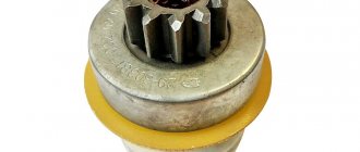
Starter 29.3708 assembled
1 – restrictor ring for gear travel; 2 – buffer spring; 3 – drive gear; 4 – overrunning clutch hub; 5 – overrunning clutch roller; 6 – outer ring of the overrunning clutch; 7 – overrunning clutch casing; 8 – axis of the gear drive lever; 9 – drive lever; 10 – drive side cover; 11 – traction relay anchor; 12 – traction relay rod; 13 – relay pull-in coil; 14 – relay holding winding; 15 – relay housing; 16 – relay cover; 17 – contact bolts; 18 – contact plate; 19 – brush; 20 – collector; 21 – stator winding; 22 – armature winding; 23 – coupling bolt; 24 – casing; 25 – armature core; 26 – starter housing; 27 – stator pole; 28 – drive ring.
Electrical diagram of VAZ-2106 (new)
General diagram of the electrical equipment of VAZ 2106 / 21061 / 21063 / 21065, produced 1988 - 2001.
1 — front lights; 2 — side direction indicators; 3 - battery; 4 — battery charge indicator lamp relay; 5 – relay for turning on low beam headlights; 6 — relay for turning on the high beam headlights; 7 – starter; 8 – generator; 9 – external headlights; 10 – internal headlights; 11 – fan motor activation sensor; 12 — electric motor of the engine cooling system fan; 13 – sound signal; 14 – ignition coil; 15 – ignition distributor; 16 – spark plugs; 17 — carburetor solenoid valve; 18 – coolant temperature indicator sensor; 19 – engine compartment lamp; 20 – reverse light switch; 21 – oil pressure indicator sensor; 22 – low oil pressure indicator sensor; 23 – indicator sensor for insufficient brake fluid level; 24 — windshield wiper gearmotor; 25 – switch*; 26 — windshield washer electric motor; 27 – fan motor activation relay**; 28 – voltage regulator; 29 – windshield wiper relay; 30 – additional fuse block; 31 – main fuse block; 32 – relay-interrupter for alarm and direction indicators; 33 – relay for turning on the heated rear window***; 34 – brake light switch; 35 – plug socket for a portable lamp****; 36 – additional resistor of the heater electric motor; 37 – heater electric motor; 38 – heater motor switch; 39 – hours; 40 – glove box lighting lamp; 41 – cigarette lighter; 42 – alarm switch; 43 – instrument lighting regulator; 44 – brake fluid level indicator lamp; 45 – three-lever switch; 46 – ignition switch; 47 – rear window heating switch***; 48 – rear fog lamp switch; 49 – external lighting switch; 50 – lamp switches located in the front door pillars; 51 – gearmotors for electric windows of the front doors***; 52 – lamp switches located in the rear door pillars; 53 – parking brake warning lamp switch; 54 – interior lamps; 55 – fuel level indicator with reserve indicator; 56 – coolant temperature indicator; 57 – oil pressure indicator with low pressure indicator; 58 – tachometer; 59 – parking brake warning lamp; 60 – battery charge indicator lamp; 61 – carburetor air damper indicator lamp; 62 – side light indicator lamp; 63 – turn signal lamp; 64 – headlight high beam indicator lamp; 65 – speedometer VAZ-2106; 66 – carburetor air damper warning switch; 67 – power window switch for the left front door***; 68 – relay for turning on the electric windows of the front doors***; 69 – power window switch for the right front door***; 70 – rear lights; 71 – license plate lights; 72 – sensor for level indicator and fuel reserve; 73 – pads connected to the rear window heating element***; 74 – trunk lighting lamp; 75 – rear fog lamp.
The order of conditional numbering of plugs in blocks:
a – switch; b – ignition distributor sensor; c – windshield wiper and windshield wiper breaker relay; d – hazard warning and direction indicator breaker relay; d – three-lever switch.
* Installed if a vehicle uses a contactless ignition system. In this case, an ignition distributor sensor of type 38.3706 and an ignition coil of type 27.3705 or 027.3705 must be installed. ** Since 2000, it has not been installed and electric motor 12 is switched on directly by sensor-switch 11. In this case, instead of the previously used temperature sensor 11 of type TM-108, sensor-switch 661.3710 is used. *** Installed on car parts. **** Not installed since 2000.
Wiring diagram VAZ-2106 carburetor - full view:
Technical characteristics of starter 5712.3708
| Rated power, kW | 1,55 |
| Current consumption at maximum power, A, no more | 375 |
| Current consumption in the inhibited state, A, no more | 700 |
| Current consumption in idle mode, A, no more | 80 |
Permanent magnets are attached to the steel starter housing. The starter housing and covers are secured with two studs. The armature shaft rotates in two metal-ceramic liners installed in the cover and shaft support. The torque from the armature shaft is transmitted to the drive shaft through a planetary gearbox, consisting of a central gear, three planetary gears, a carrier and an internal gear (epicyclic).
A freewheel (overrunning clutch) with a drive gear is installed on the drive shaft. It transmits torque in only one direction - from the starter to the engine, separating them after the engine starts. This is necessary to protect the starter gearbox and armature from damage due to excessive speed.
The traction relay is used to engage the drive gear with the ring gear of the engine crankshaft flywheel and turn on the power to the starter motor. When the ignition key is turned to the “starter” position, voltage is supplied to both windings of the traction relay (retracting and holding). After closing the contacts of the traction relay, the retractor winding is turned off.
The operating voltage of the traction relay should be no more than 8 V at 20±5 °C. If this is not the case, there is a fault in the relay or drive. The serviceability of the drive is determined by external inspection after disassembling the starter. The faulty relay is replaced.
Starter type 29.3708 is a four-brush DC electric motor with mixed excitation and an electromagnetic two-winding traction relay.
We give definitions
When studying the features of a starter, it is worth highlighting the following terms:
- Starter power is a parameter that characterizes the amount of energy developed by a DC motor during the engine starting process. The nameplate and rated power are equal when the starter rotates without load. At the moment of startup, inrush currents arise that are several times greater than the rated current.
- The minimum starting frequency is a parameter by which one can judge the crankshaft speed under optimal conditions for mixture formation and ignition.
- Torque of resistance to rotation - the value of the torque of resistance to rotation of the motor shaft.
Technical characteristics of starter 29.3708
| Rated power, kW | 1,3 |
| Current consumption at maximum power, A, no more | 260 |
| Current consumption in the inhibited state, A, no more | 500 |
| Current consumption in idle mode, A, no more | 60 |
In the starter housing, four poles with excitation windings are secured with screws, three of which are series and one is shunt. The body together with the covers are tightened with two bolts. The anchor is with an end commutator. The rear end of the armature shaft rotates in a cermet bushing pressed into the cover, and the front end rotates in a bushing pressed into a blind hole in the clutch housing.
An overrunning clutch (freewheel) with a drive gear is installed on the drive shaft. The overrunning clutch transmits torque in only one direction - from the starter to the engine, separating them after the engine starts. This is to protect the starter armature from damage due to excessive speed.
The traction relay is used to engage the drive gear with the ring gear of the engine crankshaft flywheel and turn on the power to the starter motor. When the ignition key is turned to the “starter” position, voltage is supplied to both windings of the traction relay (retracting and holding). After closing the contacts of the traction relay, the retractor winding is turned off.
The operating voltage of the traction relay should be no more than 9 V at (20±5) °C. If this is not the case, there is a fault in the traction relay or in the drive. The serviceability of the drive is determined by external inspection after disassembling the starter. The faulty traction relay is replaced.
Wiring diagram VAZ 2106 (injector)
1 controller 2 electric fan of the cooling system 3 ignition system harness connector to the left mudguard harness 4 ignition system harness connector to the right mudguard harness 5 fuel level indicator 6 fuel level harness connector to the fuel level sensor harness 7 oxygen sensor 8 fuel level sensor harness connector to the system harness ignition 9 electric fuel pump 10 speed sensor 11 idle speed control 12 throttle position sensor 13 coolant temperature sensor 14 mass air flow sensor 15 diagnostic block 16 crankshaft position sensor 17 canister purge solenoid valve 18 ignition coil 19 spark plugs 20 VAZ-2106 injectors 21 ignition system harness block to instrument panel harness 22 electric fan relay 23 controller power supply circuit fuse 24 ignition relay 25 ignition relay fuse 26 electric fuel pump power circuit fuse 27 electric fuel pump relay 28 ignition system harness block to injector harness 29 injector harness block to ignition system harness 30 block g guta instrument panel to the ignition system harness 31 ignition switch 32 instrument cluster 33 engine anti-toxic system display