Article navigation
The steering wheel on the UAZ loaf is arranged as follows.
Figure 5.1: Steering mechanism of cars of the UAZ-31512 family:
1 - crankcase; 2.39 — bushings; 3 - flange; 4 - bipod; 5 — washer; 6.33 - nuts; 7 — oil seal; 8.14 - bearings; 9 - plug; 10 — steering shaft; 11 - worm; 12 — bottom cover; 13 — washers; 15 — axle shaft; 16 — bipod shaft; 17 — bipod shaft; 18 — crankcase mounting screws; 19 — hinge; 20 — retaining ring; 21 — washer for the disc; 22 - spring; 23 - expansion ring; 24 — bearings; 25 — audio signal cable; 26 — contact sleeve; 27 - screw; 28,29 — plastic bushings; 30 — steering wheel; 31 — steering shaft; 32 — adjusting screw; 34 — lock washer; 35 — cotter pin; 36 — bearing; 37 — side crankcase cover; 38 - seal
Rice. 5.3 Steering gear for vehicles of the UAZ-31512 family:
1 — steering gear levers; 2 — transverse steering rod; 3 — steering bipod; 4 — bipod thrust; 5 — steering knuckle lever
Rice. 5.4 Steering of vehicles of the UAZ-3741 family:
1 — longitudinal steering rod; 2 — longitudinal steering rod lever; 3, 6 — steering linkage levers; 4, 7 — tie rod handles; 5 — transverse steering rod
The steering system of a car consists of a steering system with a steering wheel (Fig. 5.1, 5.2) and a steering mechanism (Fig. 5.3, 5.4).
Figure 5.5: Screw-type steering mechanism with spherical nut - sector:
1 — steering gear housing; 2 — shaft sector; 3 — handle nut; 4 - balls; 5,21,24 — retaining rings; 6,9,20,25 — shields; 7 — cardan; 8 — bushing; 10 - flange; 11 — screw bearings; 12 — bolts securing the steering mechanism to the frame; 13 — washers; 14 - bolt; 15 - bipod; 16 — lower crankcase cover; 17, 23, 26 — sealing rings; 18 - nut; 19 — washer; 22 — rollers; 27 — protective ring; 28 — support ring of the shaft sector; 29 — filler plug; 30 — ball bearing trough; 31 - ball bearing; 32 — drain plug; 33 - plug
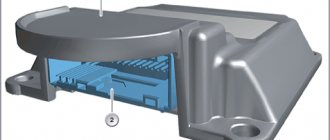
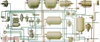
Rice. 5.6 Steering mechanism with hydraulic power steering:
1 - nut; 2, 5, 6, 19, 21, 22, 35, 39 - sealing rings; 3 - glass; 4, 10 — thrust bearings; 7 — piston bracket; 8 - bolt; 9 - crankcase; 11 — exhaust pipe hole; 12 — exhaust pipe hole; 13 — bushing; 14 - flange; 15 — tightening torque; 16, 38 — pins; 17 — ball guide; 18 — balls; 20 — crankcase channel; 23 - bipod; 24 — connecting rod nut; 25 — protective bottom cover; 26 — retaining rings; 27 — gaskets; 28 — connecting rod shaft support; 29 — rollers; 30 — connecting rod shaft; 31 — protective top cover; 32 - rotor; 33 — protective cover; 34 — distributor housing; 36 — channel of the distributor housing; 37 - bolts securing the distributor housing to the crankcase
Some cars of the UAZ-31512 family are equipped with a steering mechanism of the hinge-nut type without power steering (Fig. 5.5) or with power steering (Fig. 5.6).
Maintenance of the steering gear differs only in adjusting the steering gear.
Tighten the bolts securing the steering gear casing to the longitudinal frame element in a timely manner, check the fit of the tie rod pins, bipod and steering knuckle arm. Check the steering play, adjust the steering gear, lubricate the linkage joints and add oil to the steering gear housing or oil reservoir (for power steering) according to the lubrication chart.
Figure 5.7: Tie rod joint:
1 - plug; 2 - spring; 3 - foot; 4 - lower ball washer; 5 — upper ball washer; 6 — protective ring; 7 — spring cap; 8 - cotter pin; 9, 13 — nuts; 10 — ball pin; 11 — bumper; 12 — tip; 14 - thrust
If there is play in the hinges, screw the steering rod to limiter 1 (Fig. 5.7), then unscrew it 1/2 turn and secure it in this position.
Periodically check the tightness of the tie rod ends.
Do not allow gaps to form in the tapered joints of the arms and pins.
To remove them, loosen the nut and tighten it until it stops.
Failure to tighten these connections promptly will result in wear of the tapered holes in the arms, which will require replacement of parts.
When servicing vehicles of the UAZ-31512 family, it is necessary to pay attention to the condition of the bearings in the steering fork.
If radial play appears in the connection (axial displacement of the hub in the bearings), additional alignment of the bearings in the rocker arms is performed. Boring must be done so that the bearing shell is not destroyed.
When installed at the factory, crosshead bearings are supplied with Litol-24 lubricant and do not require replenishment during operation.
Maintenance of the power steering system includes checking the tension of the pump drive belt, checking the tightness of the hoses and their connections, checking the tightness of the pump and steering assembly seals, checking the oil level and changing the oil in the reservoir.
Repair of steering control of UAZ-3962, UAZ-3741 cars
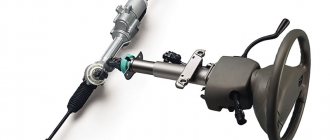
The steering of the UAZ-3962, UAZ-3741 car consists of a worm-roller type steering mechanism with a steering wheel (Fig. 14) and a steering gear (Fig. 16).
Fig. 14. Steering mechanism UAZ-3962, UAZ-3741
a-steering column with cardan joint; 1-bipod; 2-crankcase; 3-bottom cover; 4-adjusting shims for worm bearings; 5-roller; 6-worm; 7,8,29-bearings; 9-plug seal; 10-filler plug; 11-gasket; 12-side crankcase cover; 13-pin; 14-lock washer; 15.35 bushings; 16-shaft bipod; 17-cuff; 18-washer; 19-nut; 20-steering wheel; 21-column; 22- steering shaft; 23-bipod shaft bearing; 24- mesh clearance adjusting screw; 25-cap nut; 26-axis roller; 27-oil seal; 28-wire horn; 30.39-plastic bushings; 31-screw; 32-spacer sleeve; 33-protective washer; 34-hinge; 36-circlip; 37-spring; 38-pin bushing
Rice. 16. Steering gear UAZ-3962, UAZ-3741
1- longitudinal steering rod; 2- longitudinal steering rod lever; 3.6-levers steering linkage; 4.7 - tie rod ends; 5- tie rod
Rice. 15. Steering mechanism UAZ-3741, UAZ-3962 with power steering
1-nut; 2,5,6,19,21,22,35,39 - O-rings; 3-glass; 4.10-thrust bearings; 7-piston-rack; 8-screw; 9-crankcase; 11-injection hose fitting; 12-fitting drain hose; 13-sleeve; 14-cuff; 15-torsion bar; 16.38-pins; 17-ball drive; 18-balls; 20-channel in the crankcase; 23-bipod; 24-nut bipod; 25-protective bottom cover; 26-rings; 27-adjusting washers; 28-bipod shaft support; 29-rollers; 30-shaft bipod; 31-top protective cover; 32-rotor; 33-protective cap; 34-distributor housing; 36-channel in the distributor housing; 37-bolts securing the distributor housing to the crankcase
Removing the steering mechanism of UAZ-3741, UAZ-3962
Removing the steering mechanism of UAZ-3741, UAZ-3962 is carried out in the following order:
— Remove the turn signal switch.
— Disconnect the signal wire.
— Remove the signal button and contact parts.
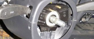
— Unscrew the steering wheel fastening nut 2-3 turns and, using a puller, loosen the steering wheel fastening on the steering shaft cone.
— Unscrew the steering wheel nut and remove the steering wheel.
On vehicles with a steering column with a universal joint (see Fig. 14a), removal of the steering mechanism is possible without removing the steering column.
Dismantling the steering mechanism of UAZ-3962, UAZ-3741 worm-roller type
Disassemble the UAZ-3741, UAZ-3962 worm-roller steering mechanism in the following order:
— Unscrew the nut and remove the lock washer from the adjusting screw.
— Unscrew the bolts securing the side crankcase cover.
— Using a light blow of a copper or aluminum drift on the end of the bipod shaft, remove the bipod shaft along with the roller and cover and carefully remove the gasket.
— By screwing the adjusting screw into the side cover of the crankcase, remove the side cover and the adjusting screw from the bipod shaft.
— Unscrew the bolts securing the lower crankcase cover and remove the cover along with the gaskets, the outer ring of the lower bearing and the separator with rollers.
— Take out the crankcase shaft with the worm assembly and the separator with the rollers of the upper bearing.
— Press the outer ring of the upper bearing, the steering gear shaft cuff, the bipod shaft cuff and the bipod shaft bushing out of the steering gear housing only if they are replaced.
Assembling the steering mechanism of UAZ-3962, UAZ-3741, worm-roller type
Assemble the UAZ-3741, UAZ-3962 worm-roller steering mechanism in the reverse order of disassembly, taking into account the following:
— In case of replacing the worm when pressing it onto the shaft, it is necessary that the high spline of the worm coincides with the keyway of the shaft. The discrepancy between the end of the shaft and the end of the groove on the worm should not exceed 0.25 mm.
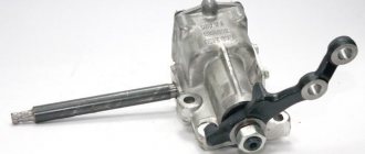
GUR UAZ 469, 31519
Repair of power steering shnkf 453461130 for UAZ 469
Flow
Problem: the power steering gearbox leaked, it started dripping, and then it started leaking like a bucket, I bought a repair kit for cuffs and decided to repair it.
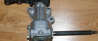
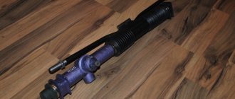
I unscrewed all the bolts and all the connections and here he is on the ground
Patient. On the operating table, see what the autopsy reveals
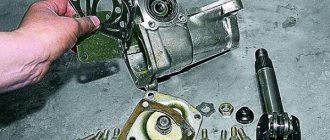
To begin with, it was necessary to remove the bipod from the shaft; I had to make an improvised puller.
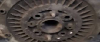
Disassembly is simple: unscrew two bolts with locknuts that secure the covers, remove the locking rings of the covers and, using a hammer, begin to knock out the covers by hitting the shaft. Be careful, when they come out, a bunch of rollers will fall out, it is important not to lose them - these are shaft bearings.
Here are the covers removed, we see inside a seal of three cuffs: two plastic, black and white, and a rubber ring between them
Here they are dismantled
Removed shaft and cover seals
I replaced the cuffs and looking at the covers I saw that their holes were not in the center and realized that by turning them the backlash in the worm joint of the gearbox was adjusted.
Next, I disassembled the drive shaft cover (shaft on the steering wheel). There I replaced the oil seal and rubber rings in the cover. The main thing is not to unscrew the shaft from the piston, otherwise you will have problems for an hour. There are balls inside, which are difficult to put back in place later.
Steering shaft cover with oil seal
When disassembling, I saw why the leak started, due to the fact that the cover was not secured and the ingress of dirt and water caused corrosion and risks on the shaft, in short, it’s an ass, I don’t know if new cuffs will help
Without thinking for a long time, I decided to make a protective cap against dirt and, if I’m lucky, against oil leaks if that happens over time. To do this, I drilled two holes and cut threads for screws.
Here's the lid itself
I assembled everything, adjusted all the gaps, by eye of course, and put it in place. No leaks yet. The autopsy had almost no effect on the work of the GUR. Only by ear it seems to be buzzing less, but that’s how it is by ear. Operation will show.
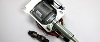
Installation of ADS-Yubei power steering kit for UAZ 469
This procedure is perhaps the most long-awaited, because... I wanted comfortable steering. All those gearboxes that were in the past either played terribly, or crunched and turned the wheels very tightly. I settled on this set thanks to reviews on the internet. Among the Borisov and Sterlitomakovsky ones, you won’t find adequate and more or less reliable ones during the day, and ready-made kits cost over 32 kilorubles in our region. What was required for installation: 1) The kit itself; 21500 rub.
The contents of the box, but I forgot to put the pump in the frame.
Steering gear
The pulley and fasteners, but where there is so much of it is not clear. Will go into reserve
2) Pump from ZMZ-409 E-2 with “ADS” gasket; 1400 rub.
3) The double pulley from the 514th internal combustion engine (I think) is textolite; 330 rub. 4) Alternator belt 2108 injection; 220 rub.
We need to resolve a small incident with the completeness of the power steering. I ordered a kit for the ZMZ-409 internal combustion engine, but with a gearbox bipod for leaf spring suspension. The supplier kindly agreed to this configuration and after a week of waiting, the kit was already in the garage. The installation began the next day.
After reading reviews about the installation of such power steering systems, and the almost stupidly written book out of the box, I realized that I would have to work hard.
To begin with, the question arose: “Should I change the pump?” I read somewhere that on the 406 pump they also attach a bracket with 2 bolts, but this is not very reliable, because if the ears of the bracket break off, then not only will you be left without power steering, but you will also have to buy a new, expensive set. I checked the play of the original pump and decided to change it to 409
The choice in our city was small. Either “ZMZ” for 1900 (“not budget”), or “ADS” for 1400 rubles (acceptable). The choice fell on ADS. In the garage, of course, there was a practically new pump from the Patriot, but from the E-3 engine and the pipe to the thermostat is thin, and therefore the thermostat housing would have to be changed, which is also not very affordable and you won’t find it. We cut off the coolant, remove the belt, pulley, pipes, pump and install a new one and the power steering pump bracket.
Removing the old pump...
... and installing a new one with a bracket (modified)
Let me get ahead of myself right away: the bracket has undergone modifications, namely, a groove has been cut for tensioning the belt, since our drive will be non-standard. We put the pump on the bracket (by the way, 2 mounting bolts from the kit had large threads, and the pump has small threads - and wherever the packers look) with a tensioner, a pulley from 514 under 2 belts on the pump, put the pump drive belt on, then the 08 belt on the drive power steering pump, tension and tighten everything.
Pump in place
This is the pump drive (I read it on one of the forums
We move under the left wing and dismantle the steering gearbox with the steering shaft. We install the gearbox from the kit, bipod, steering rod and tighten everything
Gearbox in place
Now the steering shaft. The new one had a slot on one side and a wedge on the other. It so happened that now a wedge is needed on both sides. We remove the wedge tip from the old one and repress it in place of the spline tip. Now you can put it in place. Now it's time to install the hoses. And then there was an ambush. The high pressure hose had 14mm ends, but 14mm - 16mm were required.
In the morning I called the store and laid out the essence of the problem - that the hose is not the same and there is no 16mm fitting with washers. By evening the part was received. We continued with the installation immediately. First, I released all the copper washers for better compression. The high-pressure hose was placed in front of the pump, because this way it twists less and there is practically no bending force. At the rear, not only was it next to the exhaust manifold, but it was also bent to such an extent that it was difficult to screw onto the pump. He tightened it well and began to place the tank on the wing. Everything is simple there - we drill and screw it wherever we like, as long as it doesn’t interfere with the hood. Well, finally we lay the remaining 2 hoses, cut them to length and tighten them with clamps. Lastly, I installed the lower radiator hose and the output to the RB. Everything fits perfectly, nothing pinches or rubs anywhere, although you can get tangled in the hoses. Finally, we fill out the system according to the manual (this is the only thing that was useful)
All is ready!
and testing. The joy was off the charts, there was silence from the power steering, the steering wheel was light and there was no play, but there was no yaw or drift.
Power steering from GAZ-3309 to UAZ 469
I studied this topic for a long time, but mostly they put the power steering bump on loaves and tadpoles, but on 469 this design is much less common. So I decided to add my two cents in the modifications of 469. In principle, the scheme is the same - a spool rod and a hydraulic cylinder and of course a pump, and the main difference is only that the 469 needs a spool rod from the GAZ 3309-08, its difference from gas thrust 66 to the location of the spool. On gas traction 66, the spool is at the very end of the thrust and for us it pushes against the spring, but from 3309 it suits us perfectly. Well, then it’s a matter of technology or who is good at what. Here is a photo of my version
Spool rod gas 3309 + part of steering rod gas 52 (I bought a transverse rod gas 52, cut the thread to size and screwed gas 3309 into part of the rod) and well, the bipod was already deployed to fit the cone of the gazelle tip.
Hydraulic cylinder gas-3309 aka gas-66
BMW pump 130bar
fastening the hydraulic cylinder to the bridge, the hole for the hydraulic cylinder was drilled with an 18mm drill, heated and punched with a cone, the diameter of the plate is 20mm
Well, the power steering pump mount is located in our factory place of the generator
Well, the whole power steering device just needs to be connected and installed. I can’t wait to try it out; it should turn out to be a powerful design.
Power steering BMW
UAZ 31519
I purchased a ZF power steering kit from a BMW in body 28, for its implementation it was necessary: — a bracket for mounting the UAZ power steering pump (in my opinion, from 3160); — production of an adapter plate for the steering gear; - steering shaft crosspiece; — enlarged washers and replacement of radiator mounting bolts (lifting it by 15-20mm is required); — the bipod was not found from the Volga, so I made it welded from 2 (unfortunately there is no photo); — double-groove crankshaft pulley; - 1250mm belt... The installation procedure has already been sucked in more than once, so I’ll only say about the pitfalls: 1) my diameters of the flanges on the steering shaft differed by 1mm (Bekhov’s narrower) so I had to carefully drill them out, 2) the pump bracket had to be made a little shorter , by cutting off a 10mm strip from it... 3) the double-groove pulley had to be moved 10mm forward, otherwise the belts would not stand up due to the pipes; 4) I eventually had to bend the bipod upwards, otherwise it would end up as the lowest point of the bridge, i.e. any serious obstacle could simply break it at once... in general, I’m happy with the result - parking in the city is noticeably easier.
https://www.drive2.ru/l/5531934/, https://www.drive2.ru/l/4391810/, https://www.drive2.ru/l/4034945/, https://www .drive2.ru/l/1167359/
next article:
Steering tips "Gazelle" in UAZ 469
I installed new ADS steering ends, but the seats for them were already well worn out, as a result
Rating 5.00 [1 Vote]
Device
The working pair of the steering gear is a globoidal worm and a double-ridge roller. A worm pressed onto a hollow shaft is installed in the steering gear housing on two tapered roller bearings.
To ensure the reliability of the connection between the shaft and the worm, a keyway is made and splines are cut on the worm shaft. A double-ridge roller is in constant engagement with the worm.
Its annular grooves located inside provide a working surface for a double-row ball bearing. It is mounted on an axis, which is mounted in the head of the bipod shaft.
This shaft rotates in two bearings at once: a bronze bushing pressed into the crankcase and a cylindrical roller bearing. This element is installed in the crankcase cover on the side of the steering gearbox.
The shaft head shank fits into the groove of the adjustment screw. It is screwed into the crankcase cover on the side. The adjustment screw is secured with a pin and a lock washer, which are pressed into the cover. The mechanism is closed with a nut and cap.
With its upper end, the steering shaft enters the bearing, rotating on it. The bearing is pressed into the column housing. The bearing spacer is prevented from moving by a special spring.
Repair of steering gearbox UAZ Bukhanka
After disassembling the mechanism, wash and inspect the parts. If you find peeling of the heat treatment layer, cavities, excessive wear, or cracks on the working surfaces of the worm, screw, rack nut, sector shaft, excessive wear, or cracks, they should be replaced immediately.
Screw and worm bearings should be replaced with new ones if all adjusting shims are removed to eliminate axial play or if there is damage on the working surfaces of balls, rollers, and rings.
If shells, cracks, nicks, dents are found on the working planes of the roller, bipod shaft, if there is play in the bearings or fit on the axle, it is necessary to drill out its head and remove the roller.
Insert a new roller and axle into the shaft groove. It can be secured using electric welding on the bipod shaft of the old axle - on the side of the drilled head, and on the new axle - on both sides.
Under no circumstances should the roller be allowed to overheat. If you find cavities, dents, cracks, or excessive wear on the planes under the rollers, immediately replace all rings of the sector shaft support with new ones.
If there is noticeable twisting of the splines, the bipod shaft should be replaced. If excessive wear occurs on one side of the crankcase bronze bushing, replace it with a new one. Having pressed a new bushing into the crankcase, iron it with a brooch to a diameter of 35 +0.027 mm.
Excessive free play
This problem is evident when the free play of the Bukhanka steering wheel exceeds 40 mm, provided that it is measured directly on the rim of the steering wheel.
Causes
- The bolts securing the crankcase to the spar bracket have become loose.
- The bipod fixation nut is not tightened sufficiently.
- Failure of adjustment or excessive wear of the worm bearing tightening elements.
- Failure of adjustment or excessive wear of the engagement elements of the rollers and worm.
- Weak tightening of ball pin cones.
- Weak fixation of the steering knuckle arms.
- Excessive clearances in steering linkage joints.
- Excessive gaps in the sealing of the ends of the springs (front chassis).