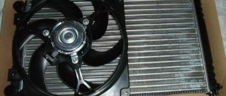
Such an important element as the VAZ 2114 cooling fan is designed to supply a directed air flow to the radiator in order to better cool the liquid inside it.
At a time when the car is moving at high speed, the need for forced (using a fan) cooling is small or absent altogether - after all, the incoming air flow copes with the cooling function without outside help. But when driving at low speeds or when parked with the engine running, additional cooling is simply necessary.
Cooling fan VAZ 2114
The fan is turned on automatically, due to an electronic controller that reads the temperature using a temperature sensor. If the temperature reaches 103 C, the cooling system starts.
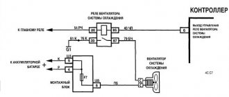
VAZ 2114 (injector): circuit diagram for switching on the cooling fan
Engine overheating is an undesirable situation for any car model. Problems with cooling on the VAZ 2114 must be resolved promptly, because An increase in temperature above normal can lead to a breakdown of the gasket under the block head, and then to the appearance of cracks in the block itself. There are several reasons for a sharp increase in engine temperature, but one of them is the failure of the cooling fan. To do the repair yourself, you need to understand what the VAZ 2114 cooling fan diagram (injector) looks like.
VAZ 2114 cooling fan diagram
The principle of operation of the fan is simple: when voltage is applied to the motor with the impeller, the blades begin to rotate, which is why the antifreeze or antifreeze in the cooling system cools down. A working unit operates only when the temperature rises, so its constant operation can also be called a malfunction.
If there are no signs of “life” of the fan, you should not rush and go to service. If you have the skills and instructions with a motor connection diagram, you can determine the malfunction yourself. The photo below shows a detailed connection diagram for the VAZ 2114 cooling fan. It includes the main components of the system responsible for the timely activation of the airflow.
Note that early versions of the second generation Samara came with a carburetor injection system. The connection diagram for the fan motor is different on them. The above diagram shows the connection paths on the injection versions of the 14th and 15th models. Successful operation and timely switching on of the fan depends on the integrity of all components shown in the diagram:
- Fan electric motor;
- Mounting block containing the relay and fuse;
- Wiring and blocks with plugs;
- Injection system controller;
- Grounding point.
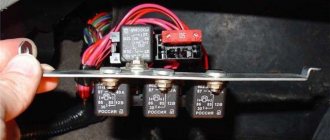
If you have a detailed wiring diagram for turning on the VAZ 2114 cooling fan at hand, then you can identify some problems yourself. For example, if the electric motor fails to turn on, you can check the condition of the relay or fuse. The relay responsible for the operation of the engine blower is located under the panel in the cabin.
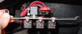
The first relay (from left to right) is responsible for activating the fan. Often replacing it is enough to restore the operation of the device.
Fuse box diagram and location on VAZ-2114, 2115 and 2113
Remember one important thing, before you start disassembling the stove, wiper, headlight or anything else - make sure that the fuse responsible for this circuit has not blown
