We reveal such a problem on a NIVA car as non-working (not turning on) radiator cooling fans. What could be the reasons? The first thing you need to do is check the fuses; they can be changed in a couple of minutes.
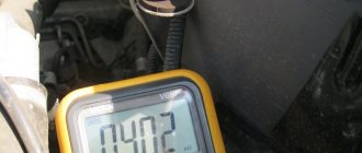
The fuses are located here:
It's 30 amp. We take them out and check them for integrity. If the fuses are blown, there are several reasons for this that will need to be corrected, otherwise they will continue to burn.
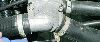
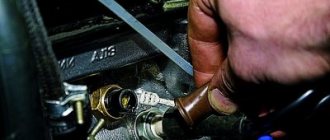
One of the reasons is that the fans are wedged, the fuses cannot withstand the load and burn, the second reason is that the fuses are not 30 Amps, but 15 or 20, they are not designed for such a load and they burn. The third reason is these two plugs:
It happens that they become clogged with dirt, water, rust, short out, or melt. Very often they close up when overcoming water obstacles, then dry out and start working again.
The fourth reason is the rest of the wiring, you need to look along the entire length, look for fraying, melting, etc. We have listed everything that relates to fuses, let's move on.
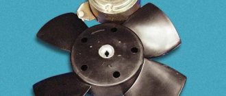
Then pay attention to whether the fans are jammed, this can happen due to wear of the bearings, try to twist the blades, just do this not with your hands, but with a stick.
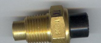
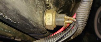
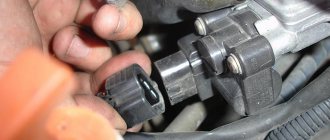
From this coolant temperature sensor, the controller reads information to turn on the fans:
If, for example, your radiator fans are constantly running and they never turn off, then most likely the problem is in this sensor.
We tried to write in text the most common reasons why the radiator fans on the NIV do not turn on or do not work, if this does not help you, watch the video below for more details, several more possible reasons are given there, and also tells how to emergency and force start radiators in the field.
More details about the problem of fans not working on Niva:
The connection diagram for Niva VAZ-21214 fans is identical to the diagram for other cars of the VAZ family. The only difference is the presence of two fans, which are turned on using two relays. This is caused by the engine working under heavy loads when driving off-road. In city conditions this is practically not necessary, with the possible exception of driving in traffic jams in hot weather. When turned on, fans create some discomfort as they make noise. You can reduce noise by reducing the rotation speed of the electric motors or turning off one of the fans. In the second case, the second fan can be turned on forcibly using a button or key.
Niva with ECM
As you know, the first Russian SUV Niva was born back in the days of the Soviet Union. At that time, in the USSR they did not even think about an electronic engine control system; the entire process of operation of the internal combustion engine was mechanical. The engine was supplied with fuel through a carburetor. At present, the Niva still continues to be produced, but with its ancestors, the modern Niva has only the body left and it has undergone minor modifications.
The carburetor was replaced with an injector, the interior was changed and the appearance of the car was transformed, but still the Niva remained Niva. The legendary Niva cross-country ability did not deteriorate after these modifications, but became much more comfortable.
In this article we will talk about the sensors of the engine control system in the injection Niva, namely, it describes in detail each of the sensors, where it is located and what function it is responsible for, as well as the signs of sensor malfunction are described in detail.
Fan malfunctions
Let's look at what malfunctions of the Niva cooling fan may occur and how to identify them. The most common malfunction is blown fuses.
The fuse blows.
A single occurrence of such a malfunction does not indicate a faulty wiring or the fans themselves. During operation, fuses heat up and eventually fail. They are easy enough to replace. They are located on a carburetor car in the lower fuse block, and on an injection car in an additional block near the driver's door pillar.
If the fuses blow immediately when the fans are turned on, then it is necessary to find a short circuit or replace the fan. To determine the location of the malfunction, it is enough to disconnect the connector on the fan motor and connect the wires on the radiator sensor with each other with the ignition on.
On an injection engine, to check it is necessary to remove the chip from the temperature sensor, which is located on the thermostat. In this case, the engine control unit will go into emergency mode and activate a program for working with a faulty temperature sensor and turn on the fan relay. If the fuse burns out, then it is necessary to find and eliminate the short circuit. If the fuse remains intact, then the problem is most likely in the fan motor. Faulty fans are stuck or difficult to rotate. This may be caused by the stator magnet falling off or the armature bushings wearing out. A faulty fan should be replaced.
The fan does not turn on
Another common malfunction is when the fan does not turn on when the operating temperature is reached. The reason may be a malfunction of the fan sensor on a carburetor car or the engine control unit on an injection car, a relay malfunction, broken wires, or a malfunction of the fan motor.
It is better to start troubleshooting by checking the temperature sensor or control unit. This is done as described earlier by bridging the wires on the carburetor engine sensor or removing the chip from the temperature sensor on the injection engine. If the fans do not work, then you need to check the power relay.
The relays are located under the instrument panel on the front wall. To check, remove the chip from the relay and check for the presence of power at pins 30 and 85. If there is no power, check the condition of the fuse and wires. If there is power, connect terminals 84 and 85 of the relay with a test lamp. If the warning lamp does not light up, then the wire from the ECU connector to the relay socket is broken or the ECU itself is faulty. A lit lamp indicates a relay malfunction.
To test the relay, connect pins 87 and 30 with a piece of copper wire, which should trigger the fans. If this does not happen, then connect a test lamp to the connector without removing the jumper from the relay connector. If the lamp does not light up, then connect one end of the test lamp to the housing, and with the other, check for the presence of a plus on the connector. If the control lamp does not light up, then there is a break in the wire from the relay to the fan connector. Accordingly, the glow of the lamp indicates poor contact of the negative wire with the body or a wire break. The presence of power and minus indicates a malfunction of the electric motor.
The lifespan of a Niva SUV engine largely depends on how efficiently the VAZ-2121 cooling works. After all, overheating is the first enemy of the power unit, leading to expensive repairs.
This is why the serviceability of the components and elements of the cooling circuit is so important. In order to be able to service them and identify malfunctions, you need to understand what the circuit consists of and how the Niva’s cooling functions.
Electronic engine control unit (ECU)
An ECU is a kind of computer in a car; it is in this device that the entire operation of the internal combustion engine is corrected. All sensors that are installed in the car transmit readings specifically to this unit, and based on the readings, it makes changes to the operation of the engine, which affects both the engine speed and its consumption.
Symptoms of ECU malfunction:
There can be a huge number of signs of malfunction of this unit, because signs of failure of one sensor may even indicate failure of the unit.
Delivery terms
- Moscow and the Moscow Region - to your door, to shopping malls or to regular buses.
- Balashikha and Krasnogorsk municipalities - pick up.
You can find out more detailed information in the “Delivery conditions” section.
offers a wide range of UNKNOWN BRAND spare parts at wholesale prices. We stock both original truck spare parts and analogues (equivalent replacements) from other manufacturers.
Attention! You can buy the VAZ-2101-07,2121-21213 fan switching sensor immediately after registration. Registration on the site is required so that you can get prices for all UNKNOWN BRAND spare parts and products from other manufacturers from our huge range, as well as delivery times and availability in warehouses!
Attention!
buy UNKNOWN BRAND 21010382801082 Fan switch sensor VAZ-2101-07,2121-21213 immediately after registration. This is necessary to assign you the status of our Honorary Client and provide you with personal prices for all UNKNOWN BRAND spare parts and products from other manufacturers presented in our huge assortment!
Mass air flow sensor (MAF)
This sensor is located near the Niva air filter box. Air flows through this sensor, which is necessary to form the air-fuel mixture. The sensor records the amount of air passing through it and sends signals to the electronic engine control unit (ECU).
Signs of a DMRV malfunction:
- Loss of vehicle dynamics;
- Increased fuel consumption;
- Unstable idling (speeds fluctuate);
- Difficulty starting the engine when the engine is warm;
CLUB CHEVROLET LACETTI/CRUZE
Fan turn-on relay If all parts are in good condition, then you will have to check two relays. One of them is responsible for the operation of the main fan, and the second is responsible for the operation of the additional fan. They are located in the mounting block under the hood. The easiest way to check is to install a known good relay. Checking The relay is checked using a jumper.
The wire should be used to close contacts 30 and If after this the fans turn on, then the reason was in the relay. They should be replaced with new ones. Checking the fans themselves You can only check the fan if you turn it on directly from the battery.
When the fans do not turn on after this, you should check the condition of the motors on them.
Crankshaft position sensor (CPS)
The Niva DPKV is installed in a special hole in the oil pump drive cover. This sensor is responsible for setting the ignition timing. The sensor takes readings from the crankshaft pulley, which has teeth and in one of the places there is “caries”, that is, several pulley teeth are missing. It is “caries” that the DPKV understands in what position the crankshaft is. The sensor itself resembles an inductive coil, which generates impulses when the crankshaft rotates and transmits them to the computer.
If the sensors fail, the car will not start.
Signs of DPKV malfunction:
- The car does not start;
- The car stalls spontaneously;
- Uneven operation of the internal combustion engine;
Niva 21214 cooling fans do not turn on
The lifespan of a Niva SUV engine largely depends on how efficiently the VAZ-2121 cooling works. After all, overheating is the first enemy of the power unit, leading to expensive repairs.
This is why the serviceability of the components and elements of the cooling circuit is so important. In order to be able to service them and identify malfunctions, you need to understand what the circuit consists of and how the Niva’s cooling functions.
Vehicle cooling network design
The cooling system of the VAZ Niva is quite effective and has undergone virtually no changes since its creation. It includes the following units and elements:
Temperature control in the Niva engine cooling network is carried out in different ways. In the carburetor model VAZ-21213, a sensor is built into the cylinder head, connected to the temperature indicator on the dashboard. On the VAZ-21214 model, where the fuel is supplied by an injector, there is a second sensor mounted in the pipe on the cylinder head. It is connected to a controller that prepares the fuel mixture depending on the heating of the power unit and turns on the fans.
There are 2 more differences in the cooling design of engines with a carburetor and an injector:
- on cars with direct fuel injection, 2 electric fans are installed on the radiator instead of 1 mechanical;
- The heating pipes for the lower part of the carburetor in model 21214 provide heating for the throttle body.
In VAZ-2131 Chevrolet Niva cars, the cooling system is generally similar to a regular Niva with an injector. The VAZ-2131 heater radiator is not equipped with a tap, which is why antifreeze flows through it all year round.
Operating principle
The Niva's cooling circuit operates under pressure, since in normal mode it does not communicate with the atmosphere. The coolant is antifreeze with a freezing point of -40 °C. It is a solution of water with ethylene glycol, the amount to fill the system is 10.7 liters. It also boils at an elevated temperature, +110 °C.
The key element in the operation of the system is the thermostatic valve, which distributes fluid flows depending on the heating of the engine. Inside the thermostat there is a damper controlled by a temperature-sensitive element. When heated, it moves the damper, opening another path for the flow. In general, the scheme works according to the following algorithm:
In the summer and transition period in VAZ-21213 and 21214 cars, the passage of coolant through the heater radiator is limited by a tap. There is no such tap on the Chevrolet Niva; the heating is turned off by redirecting the air flow past the heat exchanger.
Possible faults
To avoid problems with engine overheating, it is necessary to monitor and maintain the Niva’s cooling system.
You should check the antifreeze level in the expansion tank more often. Due to the reliability of cooling, there are not many malfunctions in it:
- When the car heats up to maximum in any weather, and the main radiator pipes are cold, the thermostat has broken. The element is not repaired, only changed.
- Electric fans turn on at random, including when the engine is cold, but if they overheat, they may not start. This means that the sensor transmitting temperature data to the controller has failed and must be replaced.
- When the indicator on the panel gives inaccurate data or does not show the temperature, you need to change the second sensor located in the cylinder head.
- The fluid level in the tank is constantly decreasing. It is necessary to look for and eliminate leaks in the pipes or in one of the radiators.
Coolant temperature sensor (DTOZH)
DTOZH on Niva is installed in the cylinder head outlet pipe. The coolant temperature sensor is a fairly simple element in its design. The sensor is based on a thermistor, which changes its resistance as the temperature changes.
One of the functions of the sensor is to start the electric engine cooling fans when the coolant temperature threshold is reached. The sensor is also responsible for starting the engine in cold weather; according to the coolant temperature readings, the electronic control unit forms the fuel mixture necessary for more proper warming up of the car engine. This can be replaced by the presence of high warm-up speeds at the moment of starting the internal combustion engine.
Signs of DTOZh malfunction:
- Cooling fans do not work;
- No warm-up speeds;
- Difficulty starting the internal combustion engine;
- Increased fuel consumption;
System structure and principle of turning on fans
Everything works as follows.
- The radiator and engine block are looped into a single system using pipes. Between them there is a rheostat - a damper with a temperature-sensitive element inside.
- When a certain temperature is reached, the damper opens and the liquid begins to circulate in a large circle.
- If passive cooling fails, the engine temperature rises. The head cooling fans come into play. When the temperature limit is overcome, the DTOZh sends an impulse to the BC.
- The processed signal closes the relay and the fan turns on. To improve system performance, the devices are paired. Dubbing helps prevent overheating if one of the devices breaks down. At the same time, the connection diagram for active coolers implies their simultaneous and separate activation.
Throttle Position Sensor (TPS)
The TPS is installed on the throttle itself and is a potentiometer. This sensor reads readings from the throttle position and transmits them to the ECU. The damper opens access to air, thereby increasing engine speed. When the damper opens, the sensor sends a signal to the control unit to increase the fuel supply, which is necessary to form a working air-fuel mixture.
The sensor that most often fails is an unreliable element of the system. Subsequently, they abandoned it and switched to an electronic throttle.
Signs of a malfunction of the TPS:
- High speed at start-up;
- Jumps in engine speed;
- Increased fuel consumption;
- Not smooth idle;
Possible malfunctions and their causes
If the fans do not turn on on time, the problem may be hiding in the following places.
- Relays or fuses have blown.
- DTOZH does not work correctly.
- The wiring of the device is damaged.
- Incorrect ECU settings.
- The fan motor is damaged or shorted.
Checking the functionality of the sensor, relays and fuses
The DTOZH is responsible for the operation of the fans; it is easy to check.
- Prepare a thermometer, multimeter, kettle or bowl of cool water.
- Immerse the sensor in a container and put it on fire, at the same time immerse the thermometer in water.
- When passing thresholds of 5 degrees, you should connect the multimeter to the sensor in resistance mode. At the same time, record the data.
- After heating the water to a boil, take the last measurements and compare the results with the reference table below. If the device indicators differ by more than 10% from the standard, the sensor is changed.
Forced activation of cooling fans
To make this possible, car enthusiasts install an additional switch into the device circuit and power it directly from the battery. The operation of the electronics is disrupted and the on-board computer may generate an error.
To fake the device, users on the network recommend using a scheme.
A relay and a forced switch are added here.
Replacing the Fan Relay
Due to the simplicity of the design, the procedure is performed according to a standard scenario. Access to the mounting block is opened, the terminal of the relay contact group is disconnected. Next, the device is unscrewed from the panel and replaced with a new one.
Knock sensor(DD)
The knock sensor is installed on the right side of the vehicle's cylinder block. A DD is needed to catch detonations in the engine and adjust the fuel mixture. The sensor itself is made on the principle of a piezoelectric element and, in the presence of vibrations in the engine, transmits impulses to the ECU, which in turn adjusts the fuel mixture.
Signs of DD malfunction:
- Increased fuel consumption;
- Uneven operation at idle (increased vibrations);
- Jerks when the car moves;
Purpose and design
This is a module designed to be included in the on-board circuit of a motor that consumes high current. The fan motor is powered by electricity with a current of 20-35A, which is unacceptable for inclusion in a low-voltage control system - the wiring will melt. The Niva has only three relays, two for the left and right fans separately and one common. Each device has its own number in the on-board network. The principle of operation and purpose of the relay is relevant for cars of all types 2004, 2010, 2022 and other years of production.
Inside, the relays have an identical design. There is a low part, a transformer and a high part. Also two pairs of contacts, one normally closed, the second open. When a pulse is applied to the lower part, a magnetic field is formed on the windings, and the contact group on the high side closes - power is supplied to the fan motor.
The cooling screw operates in two modes. When the engine heats up to 99 degrees Celsius, the first fan is turned on, after passing the 101⁰C mark, the second one is connected. If the system cannot cope, the motors switch to higher speeds.
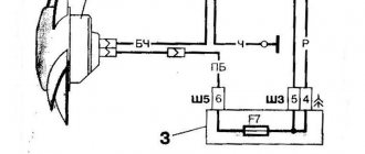
Fan relay diagram
The figure shows the power supply circuit for the electric fans of the cooling system of the installation. Design elements are presented by numbers.
- 1/7 – left and right fan motors;
- 2 – additional power relay;
- 3 – fuse;
- 4 – power controller;
- 5 – auxiliary resistor;
- 6/8 – main relay for turning on the right and left electric motor, respectively;
- A/C – negative/positive battery terminal;
- B – to the main ignition relay.
Oil pressure sensor (OPS)
The oil pressure sensor is located on the right side of the cylinder block and is screwed into the oil line fitting. This sensor is necessary to monitor the oil pressure in the engine. As you know, operating a car with low oil pressure in the internal combustion engine can damage it. When the oil pressure in the internal combustion engine decreases, the sensor closes the contact and sends a signal to the Niva instrument panel, lighting up the oil pressure indicator in the form of a red oil can.
Signs of DDM malfunction:
- Constant lighting of the oil pressure lamp;
- Oil leak from the sensor junction;
Installation of electric fans on 2121
Installation of electric fans on 2121
Post by MEW » Dec 27, 2009, 06:14 pm
Re: Forced shutdown fans 214
Post by MEW » 27 Dec 2009, 18:23
Re: Forced activation of e. fans 214
Post by MEW » 29 Dec 2009, 16:12
Starter button and interior light switch
The camera is dull and the photo is crappy
The toggle switch is in 3 positions, 1 is turned on according to the understanding of the ECU. forced: 2 disabled, 3 enabled. From the top of the toggle switch there is a red LED with a switch, connected to the circuit e. fans after relays and fuses.
Re: Forced activation of e. fans 214
Post by fedor(rus) » 06 May 2010, 20:57
Re: Forced activation of e. fans 214
Post by bambr » 06 May 2010, 23:28
I also wanted to do this for myself, but I also decided to make an indication with three lights: green - automatic, yellow - forced, red - off. Under these conditions, I couldn’t come up with an option for 1 toggle switch with 3 positions, so I installed 2 toggle switches. 1 - general on and general off, 2 - automatic and forced on. I came up with the diagram myself, I don’t remember right now - I’ll be in the garage tomorrow evening, I’ll take it home and scan it, it seems to be in my glove compartment.
Well, I’ll try to post a photo of the panel with toggle switches and lamps.
By the way, I have an electric fan from a gazelle - it blows like a hurricane.
Re: Forced activation of e. fans 214
Post by bambr » 08 May 2010, 00:03
Re: Forced activation of e. fans 214
Post by bambr » 08 May 2010, 00:11
And this is what it looks like in real life:
The quality is not great, I took it with my phone.
Re: Forced activation of e. fans 214
Post by Moonlight » May 13, 2010, 7:15 pm
Re: Forced activation of e. fans 214
Post by ALK » May 13, 2010, 9:42 pm
Moonlight, that's fine.
although automation from temperature sensors is also nice to have... missed it, forgot, etc.
Who knows what's going on behind the fence of the zoo? ©
Re: Forced activation of e. fans 214
Post by Moonlight » May 14, 2010, 01:53 pm
Re: Forced activation of e. fans 214
Post by Anton » May 14, 2010, 2:01 pm
Re: Forced activation of e. fans 214
Post by Moonlight » May 14, 2010, 2:20 pm
Re: Forced activation of e. fans 214
Post by Anton » May 14, 2010, 2:23 pm
Re: Forced activation of e. fans 214
Post by Moonlight » May 18, 2010, 7:21 pm
Here is the correct working diagram
Re: Forced activation of e. fans 214
Post by ALK » May 19, 2010, 11:45 pm
Who knows what's going on behind the fence of the zoo? ©
Re: Forced activation of e. fans 214
Post by Moonlight » May 20, 2010, 10:06 am
Re: Forced activation of e. fans 214
Post by serj44 » Aug 30, 2010, 02:51 pm
Re: Forced activation of e. fans 214
Post by bambr » Aug 30, 2010 4:23 pm
Installation of dual electric fans (from 214) on NIVU2121
Post by fraer » Jun 10, 2011 09:41
I was about to install dual electric fans (https://www.niva-faq.msk.ru/tehnika/elek. sdv_sh.htm) according to this manual.
But a number of questions arose: 1. I can’t understand about the horns; on 21213 they are located in a different place than on 2121. 2. What is the difference between the radiators 21213 (carburetor) and 2121 (old). 3. Maybe I screwed up at the very beginning and I couldn’t put them there according to the above mentioned manual. 4. Due to the fact that when removing the radiator, I tore off the plug (I started turning the wrong nut), which one is better to buy.
Re: Installing electric fans on 2121
Post by Parshmak1 » June 10, 2011, 09:57
I connected it according to this diagram
Each fan is controlled by its own thermal sensor. One temperature sensor is installed on the upper radiator pipe. The second is installed on the lower radiator pipe.
A soft start block is installed at the inlet of each fan. In the form of additional resistance GAS and relays. Installing these units allows you to avoid voltage failure in the on-board network during startup.
Source
Idle air control (IAC)
This sensor is located, just like the TPS, on the Niva’s throttle valve. The essence of the sensor's operation is to open and close the channels through which air flows to operate at idle speed. The IAC is involved in the operation of the internal combustion engine only at idle; when the speed increases, the regulator is switched off. IAC is a kind of DC motor with worm gear. Quite often the sensor fails. Subsequently, this sensor was abandoned in favor of an electronic throttle.
Signs of IAC malfunction:
- Lack of XX speed (engine stalls);
- Increased speed at idle;
- Increased fuel consumption;
Army and weapons
We reveal such a problem on a NIVA car as non-working (not turning on) radiator cooling fans.
What could be the reasons? The first thing you need to do is check the fuses; they can be changed in a couple of minutes. The fuses are located here:
It's 30 amp. We take them out and check them for integrity. If the fuses are blown, there are several reasons for this that will need to be corrected, otherwise they will continue to burn.
One of the reasons is that the fans are wedged, the fuses cannot withstand the load and burn, the second reason is that the fuses are not 30 Amps, but 15 or 20, they are not designed for such a load and they burn. The third reason is these two plugs:
It happens that they become clogged with dirt, water, rust, short out, or melt. Very often they close up when overcoming water obstacles, then dry out and start working again.
The fourth reason is the rest of the wiring, you need to look along the entire length, look for fraying, melting, etc. We have listed everything that relates to fuses, let's move on.
Then pay attention to whether the fans are jammed, this can happen due to wear of the bearings, try to twist the blades, just do this not with your hands, but with a stick.
From this coolant temperature sensor, the controller reads information to turn on the fans:
If, for example, your radiator fans are constantly running and they never turn off, then most likely the problem is in this sensor.
We tried to write in text the most common reasons why the radiator fans on the NIV do not turn on or do not work, if this does not help you, watch the video below for more details, several more possible reasons are given there, and also tells how to emergency and force start radiators in the field.
More details about the problem of fans not working on Niva:
The normal life of a vehicle depends significantly on the cooling quality of the internal combustion engine and its components. Therefore, the importance of the health of the cooling circuit is difficult to overestimate. Proper maintenance of ventilation and cooling systems is quite simple if you know the diagram of the necessary components.
Phase sensor (PF)
The phase sensor, also known as the camshaft position sensor, is installed in the cylinder head plug. Designed for phased fuel injection. Reads readings from the camshaft and transmits them to the computer; these readings are necessary for accurate distribution of the fuel mixture between the cylinders.
Signs of DF malfunction:
- Increased fuel consumption;
- Increased engine vibrations;
Brake pedal sensor
The brake pedal sensor is installed on the pedal assembly under the Niva's steering column. In cars without the E-GAZ system, it is only responsible for turning the brake lights on and off. In cars that have an electronic throttle and therefore an electronic gas pedal, this sensor affects the operation of the pedal. If the brake sensor breaks down, the gas pedal stops working.
Signs of malfunction:
- The gas pedal does not work;
- Jerking when moving at a constant speed;
- Loss of power and vehicle dynamics;
Job
The Shniva cooling system has two active cooling elements. There is a fan for the heater radiator and the main heat exchanger. The following information is relevant for cars of 2010 and other model years.
Fuses are responsible for the correct, stable operation of devices. Fuse links will protect the device from power surges and short circuits.
Pulley fan fuse: where is it located?
Located in close proximity to the corresponding relays. The stove insert is located in the main mounting block under number F18. A 25 amp fuse protects multiple circuits at once.
Speed sensor (DS)
The speed sensor of the Niva car is installed in the transfer case. The function of the sensor is to transmit vehicle speed readings. The sensor also forms the fuel mixture; when the car is moving at neutral speed, you can notice that the speed is slightly higher than when the car is running at XX while standing still. Increased speed when driving is necessary to avoid dips when turning on the speed and sharp acceleration.
Signs of DS malfunction:
- Increased fuel consumption;
- There are no increased speeds when driving at neutral speed;
- Dips during acceleration;
- The speedometer does not work;
Additional dual fan in 21213 from 21214
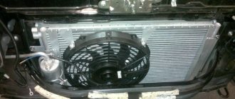
To install, you need to remove: the front radiator grille, the standard fan deflector. Unscrew the radiator mountings and tilt it into the engine compartment. The tightness of the cooling system is not compromised. If the mechanical radiator cooling fan casing is in the way, remove it. Install a dual additional fan on the side of the radiator grille.
It is necessary that there are holes for mounting on the front panel of the body. Older cars may not have them.
Place rubber seals on the upper brackets of the fan casing. Door seals are very suitable for these purposes. Place the radiator in place and secure it with bolts.
The connection diagram is the same as when installing a chisel fan.
Call us if you need engine diagnostics.
Oxygen sensor (DC, lambda probe)
An oxygen sensor, also known as a lambda probe, is installed in the exhaust system of a car. In some versions of cars, two sensors are installed before the catalyst and after the catalyst. Two sensors are installed in Niva with EURO-4 standards. The sensor captures exhaust gases and transmits readings to the ECU. If there is a large amount of unburned gasoline in the exhaust gases or, on the contrary, a small amount, then the DC makes changes to adjust the fuel mixture.
Signs of DC malfunction:
- Increased fuel consumption;
- Loss of vehicle dynamics;
- Poor engine starting;
Difference in fan connection diagram.
It doesn’t touch anything or anywhere. It is important that they wear evenly.
The initial diameter of the left hole is 6 mm, and the diameter of the leg, more precisely, the rubber band put on the leg, is 15 mm.
Let's look at the diagram Connecting Niva fans in a serial connection. The investment is cheap, but the effect is simply amazing; it’s a shame the designers at the factory didn’t think of this before. Assembly is carried out in reverse order. After this, the frame with the fans more or less normally falls into place. When removing the radiator trim, it may be that unless precautions have previously been taken to protect the screws that secure it from rust, it will be very difficult, if not impossible, to remove these screws. You can, of course, tighten the clamps as hard as you can, but as Murphy’s law says: “Everything that can go bad, goes bad,” and where is the guarantee that the pipe will not one day take or even fall off the tee? True, if something happens, with the latter it will be more difficult to unscrew the sensor back.
Heater electric motor. I had to add a third relay. When the temperature sensor is triggered, the second fan is also connected.
A useful video that shows how to remove and change fans: Important: to get to the bolt covered by the oil filter, you need to move the amplifier away from the bracket. VAZ oxygen sensor. Section: Electrical Post navigation.
Therefore, they need to be pulled out gradually. The fan does not turn off. When turned on, fans create some discomfort as they make noise. There are three rubber bands included. Well, then you can start installing the wiring. Venty on Niva 2121
Ignition module (IZ)
The ignition module is installed on the left side of the engine on a bracket. This sensor is involved in the formation of ignition. It is this that produces the high-voltage voltage necessary to create a spark in the combustion chamber of the internal combustion engine. The module has two coils, they are also autotransformers, which produce a spark in pairs, each coil for two cylinders. If one of the coils fails, two cylinders fail at once.
Signs of malfunction of the MH:
- Troubles the engine;
- Increased fuel consumption;
- Increased engine vibrations;
- Loss of traction and dynamics;
Heating and ventilation system. VAZ 21213, 21214 (Niva)
The cooling system is liquid, closed type, with forced circulation. The tightness of the system is ensured by valves in the expansion tank plug. The inlet valve is normally open (the gap between it and the rubber gasket is 0.5–1.1 mm) - in this case, the system communicates with the expansion tank. When the engine heats up, the liquid expands and is forced into the tank; when it cools, it returns back. The inlet valve closes when there is a sharp increase in pressure in the system (boiling liquid), while the outlet valve is also closed. It opens when the pressure in the system reaches approximately 0.5 kgf/cm2, which increases the boiling point of the liquid and reduces its losses. The thermal operating conditions of the engine are maintained by a thermostat and a radiator fan. On a carburetor engine, the fan is mechanically driven and mounted on the coolant pump pulley. On an engine equipped with an injection system, two electric fans are installed in front of the radiator and are activated by command from the electronic engine control unit.
Injection engine cooling system
The coolant pump is a vane, centrifugal type, driven from the crankshaft pulley by a V-belt. The pump housing is aluminum. The roller rotates in a double-row bearing with a lifetime supply of lubricant. The outer ring of the bearing is locked with a screw. A pulley hub is pressed onto the front end of the roller, and a plastic impeller is pressed onto the rear end. For the correct position of the pump pulley groove, the distance from the mating surface of the pump cover to the outer end of the hub must be 84.4 ± 0.1 mm. When installing the cover with the gasket, check the gap of 0.9–1.3 mm between the impeller blades and the pump housing. To do this, you can use plasticine rollers: they are placed on equidistant impeller blades, a cover is installed, the nuts securing it are tightened, then the cover is removed and the remaining thickness of the plasticine is measured - it is equal to the gap.
Axial and radial play in the pump bearing that can be felt by hand is not allowed. If the bearing or self-pressing seal of the pump fails, it is recommended to replace the pump cover complete with the roller and impeller.
The redistribution of liquid flows is controlled by a thermostat with a solid heat-sensitive element. On a cold engine, the thermostat valve closes the pipe leading to the radiator, and the liquid circulates only in a small circle (through the thermostat bypass pipe), bypassing the radiator. The small circle includes the heater radiator, intake manifold, carburetor heating unit (on engine 21213) or throttle assembly (on engine 21214). At a temperature of 78–85°C, the valve begins to move, opening the main pipe; in this case, part of the liquid circulates in a large circle through the radiator. At a temperature of about 90°C, the main valve opens completely, and the bypass valve closes, and all the liquid circulates through the engine radiator. The main valve stroke must be at least 6.0 mm.
You can evaluate the serviceability of the thermostat by heating the lower radiator pipe: it should be cold until the liquid temperature (according to the indicator) reaches 80–85°C, and hot when it rises to 85–90°C. The thermostat is beyond repair. In case of malfunction, loss of tightness, or deformation of the pipes, it is replaced.
The radiator consists of two vertical plastic tanks (the left one has a baffle) and two horizontal rows of round aluminum tubes with pressed-on cooling plates. To increase cooling efficiency, the plates are stamped with a notch. The tubes are connected to the tanks through a rubber gasket. The liquid is supplied through the upper pipe and discharged through the lower. There is a coolant drain plug at the bottom of the left reservoir.
For better radiator airflow, casings are designed to direct air flow from the fan(s).
On the 21213 engine, the main fan shroud consists of two halves (lower and upper), the lower half has a rubber seal on the radiator side. An additional guide casing is installed in front of the radiator. On the 21214 engine, electric fans rotate in a casing in front of the radiator.
The expansion tank is made of translucent polyethylene, which allows you to visually monitor the fluid level (3–5 cm above the “MIN” mark on a cold engine).
To monitor the coolant temperature, a sensor is screwed into the engine cylinder head and is connected to a temperature gauge on the dashboard. An additional temperature sensor is installed in the exhaust pipe of the 21214 engine, which provides information to the electronic engine control unit (see here).