Site about electronics, technology and UNIX OS
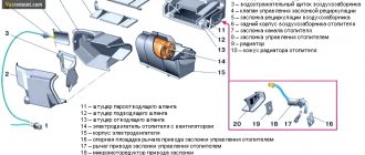
12/24/2017 by admin | 0 comments
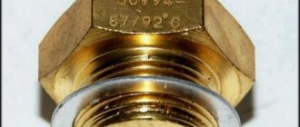
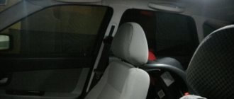
Along with the instrument panel, I did one more thing that had been planned for a long time, but I put it off just before replacing the instrument panel. This is a replacement for the interior heater switch button. I bought this button at the end of September, I really looked for it for a long time, but I still found it. It looks exactly the same as the original one, only the new one has 5 pins on the reverse side, instead of the three of the original one:
If someone decides to buy one for themselves, then its marking is “ 72.3709-02A ”. Also, in order not to deal with wires and terminals for connecting the backlight, I bought a block with eight wires connected for this button. I left only three wires in this block and removed the remaining terminals. On the remaining wires, I crimped the knife terminals on the reverse side so that they could be connected to the wires going to the heater motor. My heater wires are quite short, and it is very inconvenient to remove and put them on when removing the frame with the instrument panel. And most importantly, when installing the frame back, I had to figure out these three wires - which goes where, so that the button works correctly. Now, when you connect the block, everything will immediately be correct; you won’t be able to put it on the button incorrectly.
I decided to connect the backlight for the heater button to the glove box lighting. I crimped one wire with a special female/male terminal, and the second wire with a screw terminal. Thus, I secured the mass to the pin that secures the torpedo to the body, and connected the second wire to the light bulb in the glove box. I covered the often protruding knife terminals that go to the heater motor wires with heat shrink so that after assembly they would not shorten anything for me under the dashboard. Well, connecting the button itself after installing the frame with the tidy was quick and convenient:
Now all that remains is to tuck the button with the block inside into the frame of the instrument panel. After connecting and installing in place, all that remains is to check how the button will look and work.
Everything turned out just as I had planned. Now I have a desire to find and try to install an engine from a front-wheel drive VAZ in the stove, but again, I don’t want to buy a new engine, I will look for a used one in working condition and then experiment with it.
in short, one is clearly +, the other two are two speeds, one goes to the fan immediately, this is understandable, and the second is somewhere like in a relay that reduces the speed, now tell me which terminal I should put + in, and which 2 others
The idea is this, I don’t need a lower speed, so I use it for PTF (needless to say)
with one press, the PTF will work, and with the second press, the stove itself will work)
Switch failure
After the fuse, we check the power button. Power from the unit comes to the yellow-blue wire, as already mentioned, and if there is voltage on it, then we check the heater switch.
The ignition must be on when checking.
We take a piece of wire, connect one end to the yellow-blue one and touch the other terminals one by one; if the motor starts working when both terminals are touched, then the switch is working. If the engine does not work in one of the positions, then a conclusion is made that the switch is faulty, but for an accurate assessment you need to check the resistance.
Connecting the VAZ 2107 stove button is shown in the photo.
If there is no voltage at both terminals, the VAZ 2107 heater button needs to be replaced. To do this, pry it up with a screwdriver and pull out the button. We take out the chips from the old button and connect the new one one by one.
Electrical diagram VAZ-2107 carburetor
Electrical diagram of VAZ 2107, 21074 produced in 1988-2001 with generator 37.3701
- block headlights
- side direction indicators
- accumulator battery
- starter relay
- carburetor electro-pneumatic valve
- carburetor microswitch
- generator 37.3701
- gearmotors for headlight cleaners *
- Fan motor switch sensor
- engine cooling fan motor
- sound signals
- distributor
- spark plug
- starter
- coolant temperature gauge sensor
- engine compartment lamp
- low oil pressure warning sensor
- low brake fluid level indicator sensor
- windshield wiper motor
- carburetor electro-pneumatic valve control unit
- ignition coil
- headlight washer pump motor *
- windshield washer pump motor
- mounting block
- windshield wiper relay
- hazard warning and direction indicator relay
- brake light switch
- reverse light switch
- ignition relay
- ignition switch
- three lever switch
- hazard switch
- socket for portable lamp**
- heater fan switch
- additional resistor for the electric motor of the heater (stove)
- rear window heating indicator lamp
- low brake fluid level warning lamp
- signaling unit
- heater fan electric motor
- glove compartment lamp
- light switches on the front door pillars
- switches for warning lights of open front doors ***
- front door open warning lights ***
- connection block
- cigarette lighter
- watch
- instrument light switch
- diode for checking the serviceability of the low brake fluid level indicator lamp
- fuel level indicator
- fuel reserve indicator lamp
- speedometer
- turn signal indicator lamp
- carburetor choke indicator lamp
- battery charge indicator lamp
- carburetor choke warning switch
- instrument cluster
- econometrician
- light switches on the rear door pillars
- coolant temperature gauge
- tachometer
- parking brake indicator lamp ("handbrake")
- low oil pressure warning lamp
- high beam indicator lamp
- indicator lamp for turning on external lighting
- voltmeter
- parking brake indicator switch ("handbrake")
- outdoor light switch
- rear window heating switch with backlight
- rear fog light switch with on/off indicator *
- fog light circuit fuse
- lampshade ****
- tail lights
- level indicator and fuel reserve sensor
- connectors for connecting to the rear window heating element *
- license plate lights 2107
Wiring diagram VAZ-2107 carburetor - full view:
Common problems and solutions
Despite the simplicity of the design, the heating system of the VAZ-2107 fails quite often. Its most vulnerable places are:
- heater valve;
- fan (electric motor);
- stove radiator.
The heater valve of the “Seven”, like all classic VAZs, breaks down most often. Its most common malfunction is a leak caused by depressurization of the housing. This problem can be solved by replacing the spare part. Repairing the faucet is impossible in most cases.
Another common failure is a broken drive cable. To replace it, you will have to dismantle the tap, because it is impossible to get to its fastening on the side of the locking device without removing it. You should also monitor the cable tension. If you allow it to sag, the faucet valve will not open completely.
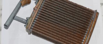
As for the fan, it cannot be called reliable. Usually it fails with the onset of cold weather. The cause of an electric motor malfunction, at best, is worn out bearings or brushes, at worst, a break or short circuit in the windings. Repairing the electric motor or replacing it can correct the situation.
The heater radiator also has two “diseases”: leaking and clogging. The first malfunction can be caused either by mechanical damage or by chemical processes. Today, radiators are made of aluminum alloy, which is not particularly resistant to technical fluids. And if old copper radiators could still be soldered, then modern ones can only be replaced.
Heat exchanger clogging also occurs as a result of chemical processes. Scale gradually settles on the walls of the device tubes and over time limits the normal circulation of the coolant. This leads to the fact that the air pumped into the cabin does not warm up to the required temperature. You can get rid of this problem by flushing the radiator with special liquids, or, in extreme cases, by replacing the device.
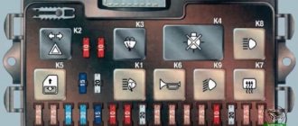
Mounting block connection diagram
P1 — relay for turning on the heated rear window; P2 - relay for turning on the headlight cleaners and washer; P3 - relay for turning on sound signals; P4 - relay for switching on the electric motor of the engine cooling system fan; P5 - headlight high beam relay; P6 - low beam headlight relay; A - the order of conditional numbering of plugs in the mounting block blocks. The outer number with the letter “Ш” in the plug designation is the block number, and the inner number is the conventional number of the plug.
Reasons for decreased performance
In addition to obvious malfunctions due to which the stove does not work or functions incorrectly, there are other problems with the heating system of the VAZ-2107 interior. The main one is a decrease in stove performance.
If the stove heats poorly, then the reason lies in:
- Malfunctions of the power plant cooling system (reduced pump performance, stuck thermostat).
- Radiator clogged.
- Formation of an air lock in the heater radiator.
- The air intake damper seal is worn out.
To find the cause of decreased performance, start by checking the heating of the heater radiator. To do this, heat the engine to operating temperature, fully open the antifreeze supply valve to the stove and hand check the degree of heating of the supply pipe before and after the valve and the radiator itself. If the pipeline is hot before the tap, but not after it, the tap is jammed. If the radiator does not warm up, the reason lies in severe clogging of the heat exchanger or a plug in it. If the pipeline does not warm up even to the tap, inspect the cooling system.
Schemes of individual blocks of the seven
Power supply system
Power plant starting system
1 - starter; 2 - relay; 3 — ignition switch; 4 - battery
Ignition system
1 - generator; 2 — ignition switch; 3 - distributor; 4 - breaker; 5 — candles; 6 - coil; 7 - battery
Contactless ignition system
External and internal lighting
Windshield wipers and washers
1 — electric motors of the windshield wiper; 2 — washer motor; 3 — mounting block; 4 — ignition switch; 5 - washer switch
Cooling Fan
1 — fan electric motor; 2 - sensor; 3 — mounting block; 4 - ignition relay; 5 - ignition switch.
Wires for connecting electrical appliances
| Connection type | Section, mm 2 | Insulation color |
| Negative terminal of the battery - vehicle ground (body, engine) | 16 | Black |
| Starter positive terminal - battery | 16 | Red |
| Positive contact of the generator - plus battery | 6 | Black |
| Generator - black connector | 6 | Black |
| Terminal on the generator “30” – white MB block | 4 | Pink |
| Starter connector “50” – starter relay | 4 | Red |
| Starter Start Relay - Black Connector | 4 | Brown |
| Ignition switch relay - black connector | 4 | Blue |
| Ignition switch output “50” – blue connector | 4 | Red |
| Ignition switch connector “30” – green connector | 4 | Pink |
| Right headlight plug - ground | 2,5 | Black |
| Left headlight plug - blue connector | 2,5 | Green, gray |
| Generator output “15” – yellow connector | 2,5 | Orange |
| Right headlight connector - ground | 2,5 | Black |
| Left headlight connector - white connector | 2,5 | Green |
| Radiator fan - ground | 2,5 | Black |
| Radiator Fan - Red Connector | 2,5 | Blue |
| Ignition switch output “30/1” – ignition switch relay | 2,5 | Brown |
| Ignition switch contact “15” – single-pin connector | 2,5 | Blue |
| Right headlight - black connector | 2,5 | Grey |
| Ignition switch connector “INT” – black connector | 2,5 | Black |
| Six-pin block of the steering column switch - “ground” | 2,5 | Black |
| Two-pin block of the steering column switch - glove box illumination lamp | 1,5 | Black |
| Glove compartment light - cigarette lighter | 1,5 | Black |
| Cigarette lighter - blue block connector | 1,5 | Blue, red |
| Rear window defroster - white connector | 1,5 | Grey |
Car wiring diagram
1 – radiator fan drive motor; 2 – relay and fuse block (mounting block); idle speed sensor; 4 – engine control unit; 5 – potentiometer; 6 – set of spark plugs; 7 – ignition control unit; 8 – electronic crankshaft sensor; 9 – electric fuel pump; 10 – tachometer 2107; 11 – lamp for monitoring the health of electronic systems; 12 – ignition system control relay; 13 – speed sensor; 14 – diagnostic connector; 15 – set of injectors; 16 – adsorber solenoid valve; 17, 18, 19 – fuse block protecting the injection system circuits; 21 – electronic fuel pump control relay; 22 – electronic relay for controlling the intake pipe heating system; 23 – intake pipe heating system; 24 – fuse protecting the heater circuit; 25 – electronic oxygen level sensor; 26 – cooling system temperature control sensor; 27 – electronic air damper sensor; 28 – air temperature sensor; 29 – pressure control sensor.
Let's sum it up
Timely diagnostics, preventive cleaning and inspection of elements of the vehicle’s heating system is a guarantee of high-quality operation of the stove. Experts recommend checking the heating system on the VAZ-2107 at least twice a year - in autumn and spring. Any driver can handle preventive cleaning and adjustments of the stove on his own; to do this, you just need to understand the structure of the heating and ventilation system of the cabin and the principle of its operation. The easiest way to do this is to always have a visual instruction manual for your car nearby.
Don’t put off any further work to improve the functioning of your car’s heating system. Proper care will ensure uninterrupted operation of the heater and a comfortable temperature in the interior at any time of the year.
Fuse and relay diagram 2107
On newer “sevens” a block with 17 fuses and 6 relays is installed. VAZ 2107 fuses on the “new” unit protect the following electrical circuits and devices:
- Reversing lamps, heater fan, rear window defroster warning lamp and relay, rear wiper motor and rear washer pump.
- Electric motor for front wipers.
- Reserve socket.
- Reserve socket.
- Power supply for heated rear window.
- Clock, cigarette lighter, power socket “carrying”.
- Signal and radiator fan.
- Turn signal lamps in emergency mode.
- “Fog lights” and a relay that regulates the voltage of the on-board network.
- Instrument panel lamps.
- Brake light bulbs.
- Right high beam headlight.
- Left high beam headlight, high beam warning lamp.
- Side lights (rear right, front left), license plate and engine compartment lighting.
- Side lights (rear left, front right), glove compartment and cigarette lighter lamps.
- Low beam (right lamp).
- Low beam (left lamp).
The block relays perform the following functions:
- Heated rear window relay.
- Headlight cleaner and washer relay.
- Signal relay.
- Cooling system electric fan relay.
- High beam relay.
- Low beam relay.
The fuse block of the VAZ 2107 (injector) is no different from the block on the carburetor “seven”. Injection models are simply equipped with an additional relay and fuse box installed in the cabin under the glove compartment. The block includes three relays - the “main” relay, the fuel pump relay and the fan relay.
Heater motor malfunction
The main engine malfunctions are the rotor getting stuck in the bushings or bearings. With such a malfunction, the fuse usually burns out, so do not install a fuse with a high current, otherwise it will burn out the tracks of the block or wiring.
The second malfunction is wear of the brushes. In this case, when voltage is applied to any of the windings, the engine will not work.
To make sure that the engine is working properly, you need to check the wiring that goes to it, as the chips may simply have come loose or the negative wire has become disconnected.