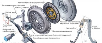
The crank mechanism (abbreviated as KShM) ensures the conversion of the translational-rotational movement of the piston inside the cylinder into the rotational movement of the engine crankshaft. For a standard four-cylinder engine, the crankshaft includes a cylinder block with a crankcase, a cylinder head, an engine sump, pistons complete with piston rings and pins, connecting rods (on which the pistons are mounted), a crankshaft and a flywheel.
The main part of the crankshaft (and the engine in general) is the cylinder block. It consists not only of cylinders (Fig. 2.7) and piston group parts, but also of a number of other elements: channels, plugs, bearings, drillings. The crankshaft, which is mounted on special bearings, rotates precisely in the cylinder block.
The crankcase is located at the bottom of the cylinder block. Coolant constantly circulates inside the cylinder block while the engine is running: in the summer it can be simple water, but in the cold season it is necessary to use antifreeze or antifreeze. Also inside the cylinder block are oil channels that belong to the engine lubrication system.
Mechanism design
The first crank devices were invented in the ancient world. In ancient Roman sawmills, the rotational motion of a water wheel, driven by the river current, was transformed into a reciprocating motion of the saw blade. In antiquity, such devices were not widely used for the following reasons:
- wooden parts wore out quickly and required frequent repairs or replacement;
- slave labor was cheaper than high technology for that time.
In a simplified form, the crank mechanism has been used since the 16th century in village spinning wheels. The movement of the pedal was converted into rotation of the spinning wheel and other parts of the device.
Steam engines developed in the 18th century also used a crank mechanism. It was located on the driving wheel of the locomotive. The steam pressure on the piston bottom was converted into the reciprocating movement of a rod connected to a connecting rod pivotally mounted on the drive wheel. The connecting rod gave the wheel rotation. This arrangement of the crank mechanism was the basis of mechanical transport until the first third of the 20th century.
The locomotive design was improved in crosshead engines. The piston in them is rigidly attached to the crosshead rod, which slides back and forth in the guides. A hinge is attached to the end of the rod, and a connecting rod is attached to it. This scheme increases the range of working movements and even makes it possible to make a second chamber on the other side of the piston. Thus, each movement of the rod is accompanied by a working stroke. Such kinematics and dynamics of the crank mechanism make it possible to double the power with the same dimensions. Crossheads are used in large stationary and ship diesel installations.
The elements that make up the crank mechanism are divided into the following types:
- Movable.
- Fixed.
The first include:
- piston;
- rings;
- fingers;
- connecting rod;
- flywheel;
- crankshaft;
- crankshaft plain bearings.
The fixed parts of the crank mechanism include:
- cylinder block;
- sleeve;
- block head;
- brackets;
- crankcase;
- other minor elements.
Pistons, pins and rings are combined into a piston group.
Each element, as well as the detailed kinematic diagram and operating principle, deserves a more detailed consideration
Cylinder block
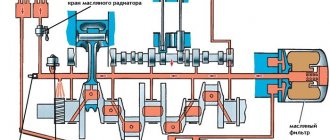
This is one of the most complex engine parts in terms of configuration. The schematic three-dimensional drawing shows that inside it is pierced by two non-intersecting systems of channels for supplying oil to the points of lubrication and coolant circulation. It is cast from cast iron or light metal alloys and contains places for pressing cylinder liners, brackets for crankshaft bearings, space for the flywheel, lubrication and cooling systems. The unit is connected to the pipes for the fuel mixture supply and exhaust gas removal system.
An oil sump-lubricant reservoir is attached to the bottom of the block through a sealed gasket. It is in this crankcase that the main work of the crank mechanism, abbreviated KShM, takes place.
The liner must withstand the high pressure in the cylinder. It is created by gases formed after the combustion of the fuel mixture. Therefore, the place of the block where the liners are pressed must withstand high mechanical and thermal loads.
The sleeves are usually made of durable steel, less often - of cast iron. During engine operation they wear out and can be replaced during a major engine overhaul. There are two main layouts for their placement:
- dry, the outer side of the liner transfers heat to the material of the cylinder block;
- wet, the liner is washed from the outside with coolant.
The second option allows you to develop more power and tolerate peak loads.
Movable and stationary parts of the crankshaft
The components of a flywheel are conventionally divided into moving and stationary components. Moving parts include:
- pistons and piston rings;
- connecting rods;
- piston pins;
- crankshaft;
- flywheel.
The fixed parts of the CVM perform the functions of the base, fasteners and guides. These include:
- cylinder block;
- cylinder head;
- crankcase;
- oil pan;
- fasteners and bearings.
Engine crankcase and sump
The crankcase is the lower part of the engine where the supports and lubrication channels for the crankshaft are located. The crankcase moves the connecting rods and rotates the crankshaft. The oil pan is a reservoir containing engine oil.
The crankcase base is subjected to constant thermal and power loads during operation. Therefore, this part has special requirements for strength and rigidity. Aluminum alloys or cast iron are used for its manufacture.
Fixed parts of the crankshaft
The engine crankcase is attached to the cylinder block. Together they form the core of the engine, the main part of its body. The block houses the cylinders themselves. The head of the internal combustion engine block is mounted on top. There are cavities around the cylinders for liquid cooling.
Location and number of cylinders
Today there are the following most popular schemes:
- in-line four- or six-cylinder position;
- V-shaped six-cylinder position at an angle of 90°;
- VR-shaped position at a lower angle;
- opposed position (pistons move towards each other from different sides);
- W-position with 12 cylinders.
In a simple inline arrangement, the cylinders and pistons are arranged in a row perpendicular to the crankshaft. This scheme is the simplest and most reliable.
Cylinder head
The cylinder head is attached to the block using studs or bolts. It covers the cylinders with pistons on top, forming a sealed cavity - the combustion chamber. There is a gasket between the block and the head. The cylinder head also houses the valve mechanism and spark plugs.
Cylinders
The movement of the pistons directly occurs in the engine cylinders. Their size depends on the stroke of the piston and its length. Cylinders operate under conditions of varying pressure and high temperatures. During operation, the walls are subject to continuous friction and temperatures of up to 2500°C. There are also special requirements for the materials and processing of the cylinders. They are made of alloy cast iron, steel or aluminum alloys. The surface of the parts must not only be durable, but also be easy to process.
The outer working surface is called a mirror. It is plated with chrome and polished to a mirror finish to minimize friction in conditions of limited lubrication. The cylinders are cast together with the block (solid) or made in the form of removable sleeves.
Pistons
The part is a steel or aluminum casting in the form of an inverted glass. Sliding along the walls of the cylinder, it takes on the pressure of the burnt fuel mixture and turns it into linear movement. Then, through the crank assembly, it turns into rotation of the crankshaft, and then is transmitted to the clutch and gearbox and through the cardan to the wheels. The forces acting in the crank mechanism set the vehicle or stationary mechanism in motion.
The part performs the following functions:
- on the intake stroke, moving downwards (or in the direction from the crankshaft if the cylinder is not located vertically) on, it increases the volume of the working chamber and creates a vacuum in it, drawing in and evenly distributing the next portion of the working mixture throughout the volume;
- on the compression stroke, the piston group moves upward, compressing the working mixture to the required degree;
- Next comes the power stroke, the part under pressure goes down, transmitting a rotational impulse to the crankshaft;
- on the exhaust stroke it goes up again, displacing exhaust gases into the exhaust system.
At all strokes, except for the working stroke, the piston group moves due to the crankshaft, taking away part of the energy of its rotation. On single-cylinder engines, a massive flywheel is used to accumulate such energy; on multi-cylinder engines, the cylinder strokes are shifted in time.
Structurally, the product is divided into the following parts:
- bottom, which absorbs gas pressure;
- seal with grooves for piston rings;
- a skirt in which a finger is secured.
The pin serves as an axis on which the upper arm of the connecting rod is fixed.
Sleeve
Removable sleeve
There are two types of sleeves - made directly in the block and being part of them, and removable. As for those made in the block, they are cylindrical recesses in it of the required height and diameter.
Removable ones also have a cylindrical shape, but they are open at the ends. Often, in order to securely fit into its seat in the block, there is a small ebb in the upper part that ensures this. In the lower part, for density, rubber rings are used, installed in the flow grooves on the sleeve.
The inner surface of the liner is called the mirror because it is highly machined to ensure the lowest possible friction between the piston and the mirror.
In two-stroke engines, several holes are made in the liner at a certain level, which are called windows. In the classic internal combustion engine design, three windows are used - for inlet, outlet and bypass of the fuel mixture and waste products. In opposed installations such as OROS, which are also push-pull, there is no need for a bypass window.
Piston rings
The purpose and design of piston rings is determined by their role in the operation of crank devices. The rings are made flat, they have a cut a few tenths of a millimeter wide. They are inserted into the annular grooves machined for them on the seal.
The rings perform the following functions:
- Seal the gap between the liner and the piston walls.
- Provide direction of piston movement.
- Cool. Touching the liner, the compression rings remove excess heat from the piston, protecting it from overheating.
- Isolate the working chamber from lubricants in the crankcase. On the one hand, the rings retain droplets of oil sprayed into the crankcase by the impacts of the counterweights of the crankshaft cheeks; on the other hand, they allow a small amount of oil to pass through to lubricate the cylinder walls. The lower oil scraper ring is responsible for this.
The connection between the piston and connecting rod also needs to be lubricated.
Lack of lubrication within a few minutes renders the cylinder parts unusable. The rubbing parts overheat and begin to collapse or become jammed. Repair in this case will be difficult and expensive.
Piston pins
The kinematic connection between the piston and connecting rod is carried out. The product is fixed in the piston skirt and serves as the axis of the sliding bearing. The parts withstand high dynamic loads during the working stroke, as well as changes in stroke and reversal of the direction of movement. They are machined from high-alloy heat-resistant alloys.
The following types of finger designs are distinguished:
- Fixed. They are fixedly mounted in the skirt, only the cage of the upper part of the connecting rod rotates.
- Floating. They can rotate in their fastenings.
The floating design is used in modern engines; it reduces the specific loads on the components of the crank group and increases their service life.
connecting rod
This critical element of the engine crank mechanism is made dismountable so that the bearing shells in its cages can be changed. Sliding bearings are used on low-speed engines; on high-speed engines, more expensive rolling bearings are installed.
In appearance, the connecting rod resembles a spanner. To increase strength and reduce weight, the cross section is made in the form of an I-beam.
During operation, the part experiences alternate loads of longitudinal compression and tension. For manufacturing, castings from alloy or high-carbon steel are used.
Crankshaft
The transformation is carried out with help.
Of the parts of the crank group, the crankshaft has the most complex spatial shape. Several articulated joints move the rotation axes of its segments away from the main longitudinal axis. The lower races of the connecting rods are attached to these remote axles. The physical meaning of the design is exactly the same as when securing the connecting rod axis to the edge of the flywheel. In the crankshaft, the “extra”, unused part of the flywheel is removed and replaced with a counterweight. This allows you to significantly reduce the weight and dimensions of the product and increase the maximum available speed.
The main parts that make up the crankshaft are as follows:
- Shakey. Serve for fastening the shaft in the crankcase brackets and connecting rods on the shaft. The first are called main, the second - connecting rod.
- Cheeks. They form the knees that give the knot its name. Rotating around the longitudinal axis and pushed by connecting rods, they convert the energy of the longitudinal movement of the piston group into rotational energy of the crankshaft.
- Front exit part. A pulley is placed on it, from which the shafts of the auxiliary systems of the engine - cooling, lubrication, distribution mechanism, and generator - rotate using a chain or belt drive.
- Main output part. Transfers energy to the transmission and further to the wheels.
The back part of the cheeks, protruding beyond the axis of rotation of the crankshaft, serves as a counterweight for their main part and the connecting rod journals. This allows you to dynamically balance a structure rotating at high speed, avoiding destructive vibrations during operation.
For the manufacture of crankshafts, castings from light high-strength cast iron or hot stampings (forgings) from hardened steel are used.
Flywheel
The flywheel is attached to the crankshaft shank flange. It is a carefully balanced cast iron disk of a certain mass. In addition to ensuring uniform rotation of the crankshaft, the flywheel helps overcome compression resistance in the cylinders when starting the engine and short-term overloads, for example, when starting a vehicle. A ring gear is attached to the flywheel rim to start the engine from the starter. The surface of the flywheel that comes into contact with the clutch driven disc is ground and polished.
Rice. Crankshaft: 1 - toe; 2 — connecting rod journal; 3 - molar neck; 4 - cheek; 5 - counterweight; 6 - shank with flange
Crankcase
It serves as the structural basis of the entire engine; all other parts are attached to it. External brackets extend from it, on which the entire unit is attached to the body. A transmission is attached to the crankcase, transmitting torque from the engine to the wheels. In modern designs, the crankcase is made as a single part with the cylinder block. Within its spatial framework, the main work of the components, mechanisms and parts of the motor takes place. A pan is attached to the bottom of the crankcase to store oil to lubricate the moving parts.
Operating principle of the crank mechanism
The operating principle of the crank mechanism has not changed over the past three centuries.
During the power stroke, the working mixture ignited at the end of the compression stroke quickly burns, the combustion products expand and push the piston down. He pushes the connecting rod, which rests on the lower axis, spaced apart from the main longitudinal axis. As a result, under the influence of tangentially applied forces, the crankshaft rotates a quarter of a turn in four-stroke engines and half a turn in two-stroke engines. Thus, the longitudinal movement of the piston is converted into rotation of the shaft.
Calculation of the crank mechanism requires excellent knowledge of applied mechanics, kinematics, and strength of materials. It is entrusted to the most experienced engineers.
Design (production) of the rocker mechanism
Despite the apparent simplicity of the rocker mechanism, in order for it to work effectively, a lot of work is required to calculate and design it. The following main aspects are considered:
- productivity and efficiency;
- cost of production and operation;
- fault tolerance and overhaul life;
- accuracy of action;
- safety.
Considering the complexity of the mutual influence of these aspects on each other, the calculation of the crank mechanism is a multi-stage iterative task.
During the design, the following types of calculations and modeling are carried out:
- kinematics calculation;
- dynamic calculation;
- static calculation.
Typically, design and calculation are divided into the following stages:
- Determination of the required law of motion by calculation-analytical or graphic-analytical method.
- Kinematic modeling. Implementation of the general plan, speed plan, graphical modeling of moments of inertia, graph of energy-mass dependencies.
- Force modeling. Construction of a plan of accelerations, diagrams of forces applied to links in several positions.
- Synthesis of rocker-lever mechanism. Plotting graphs of displacement, speed, acceleration using the graphical-differential method. calculation of the dynamics of the rocker mechanism and its dynamic synthesis.
- Checking for compliance with the law of motion. Final profiling of the wings.
- Checking for compliance with health and safety standards.
- Release of drawings.
For a long time, the calculation and design of the rocker mechanism was a very labor-intensive process that required great concentration and care from the designer. Recently, the development of computer technology and software products of the CAD-CAE family has significantly facilitated all routine calculation operations. The designer just needs to select a suitable kinematic pair or link from the library programs supplied by the manufacturer and set their parameters on a three-dimensional model. There are modules on which it is enough to graphically display the law of motion, and the system itself will select and offer a choice of several options for its kinematic implementation.
Malfunctions that occur during the operation of the crankshaft and their causes
Malfunctions can occur in different elements of the crank group. The complexity of the design and combination of parameters of engine connecting rod mechanisms makes it necessary to pay special attention to their calculation, manufacture and operation.
Most often, failures result from non-compliance with the operating modes and maintenance of the motor. Poor quality lubrication, clogging of oil supply channels, untimely replacement or replenishment of oil in the crankcase to the specified level - all these reasons lead to increased friction, overheating of parts, and the appearance of scuffs, abrasions and scratches on their working surfaces. The oil filter should be changed every time you change the oil. In accordance with the maintenance schedule, fuel and air filters also need to be changed.
Malfunction of the cooling system also causes thermal deformation of parts, up to their jamming or destruction. Diesel engines are especially sensitive to the quality of lubrication.
Problems in the ignition system can also lead to carbon deposits on the piston and its rings. Coking of the rings causes a decrease in compression and damage to the cylinder walls.
It also happens that the cause of a breakdown is low-quality or counterfeit parts or materials used during maintenance. It is better to purchase them from official dealers or trusted stores that care about their reputation.
Application area
Today, the ratchet as a part is used in the creation of various industrial units with components of engineering structures. At the same time, stable operation of various small elements of tools can be ensured. This point indicates the versatility of using ratchet mechanisms.
From a technical integration point of view, the device outperforms many other designs.
Very often, manufacturers use a ratchet as an element through which operating parameters are set. An example is fixing the cutting step in a certain range. In addition, installation is carried out during the direct manufacture of machine tools.
Recently, installation has been carried out in cylindrical grinding machines, the device provides radial feed. The mechanism is found in jacks and various winch systems, wind-up cars and other devices.
List of KShM malfunctions
The most common mechanism failures are:
- wear and destruction of the crankshaft connecting rod and main journals;
- grinding, chipping or melting of plain bearing shells;
- contamination of piston rings by combustion carbon deposits;
- overheating and breakage of rings;
- accumulation of carbon deposits on the piston head leads to its overheating and possible destruction;
- Long-term operation of the engine with detonation effects causes the piston crown to burn out.
The combination of these faults with a malfunction in the lubrication system can cause misalignment of the pistons in the cylinders and engine seizure. Elimination of all these breakdowns involves dismantling the engine and its partial or complete disassembly.
Repairs take a long time and are expensive, so it is better to identify malfunctions in the early stages and correct problems in a timely manner.
Note.
A considerable proportion of attached motor equipment is mounted on the cylinder block, and when the engine is turned on, it works with it as a single unit.
As for the purpose and principle of operation of the piston and other parts of the piston group, we have already discussed this above. Let us only recall that under the force of powerful pressure that is formed in the cylinder after combustion of the working mixture, the piston moves down and transmits its movement through the connecting rod (on which it is installed) to the crankshaft, forming the very torque with which the car is driven into movement.
Know that the internal combustion engine operates in a rather harsh regime. At idle speed (that is, when the engine is running, but the car is stationary in neutral), the crankshaft rotates at a speed of 600-900 revolutions per minute (or about 10-16 revolutions per second). When driving at medium speed, the engine works even more intensely, and the crankshaft rotates at a speed of 2000 to 3000 rpm. And in modern sports cars, the crankshaft rotation speed can exceed 200 revolutions per second (10,000 - 13,000 revolutions per minute).
Consequently, the pistons in the cylinders move up and down very quickly. We have already noted earlier that in one full revolution of the crankshaft, the piston manages to cover the distance between TDC and BDC twice. So: he performs these movements literally in a fraction of a second. If we add to this powerful pressure, as well as high temperature in each cylinder, then the operating conditions of the internal combustion engine can be called extreme.
Signs of malfunctions in the operation of the crankshaft
For timely detection of failures and negative processes beginning to develop in the crank group, it is useful to know from external signs:
- Knocks in the engine, unusual sounds during acceleration. Ringing sounds are often caused by detonation phenomena. Incomplete combustion of fuel during the power stroke and its explosive combustion during the exhaust stroke lead to the accumulation of carbon deposits on the rings and the piston crown, deterioration of their cooling conditions and destruction. It is necessary to fill in high-quality fuel and check the operating parameters of the ignition system on the stand.
- Dull knocks indicate wear on the crankshaft journals. In this case, you should stop operating, grind the journals and replace the liners with thicker ones from the repair kit.
- A sound that “sings” at a high, loud note indicates the possible beginning of melting of the liners or a lack of oil when the speed increases. You also need to urgently go to the service center.
- Gray puffs of smoke from the exhaust pipe indicate excess oil in the working chamber. The condition of the rings should be checked and replaced if necessary.
- A drop in power can also be caused by ring coking and decreased compression.
If you notice these alarming symptoms, do not postpone your visit to the service center. A seized engine will cost much more, both in money and time.