What are the reasons for the charging failure, how to fix the problem on the road or in the garage - this is discussed in this manual.
The electrical circuit of the LADA Niva 4×4 is built according to a classic layout and has undergone virtually no changes since the start of production. Why, knowing its weak points and moving from the obvious to the complex. You will quickly find the root cause.
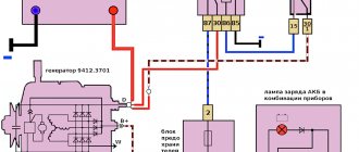
Generator connection principle, drawing:
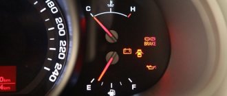
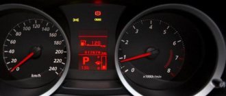
Basic information about the state of the charger can be obtained from the behavior of the instrument cluster - flashing of the indicator, emergency operation of electrical equipment (headlights, interior lighting, heater) and the engine.
Device Description
On Niva 21214 cars there is a generator of type 9412.3701, on VAZ 21213 - type 371.3701, on Niva Chevrolet there is a generator 2123. All of them are alternating current electric machines with electromagnetic excitation, having a built-in rectifier unit with silicon diodes and an electronic voltage regulator. The maximum current produced by the generator unit type 9412.3701 is 80 A, voltage - 13.2 - 14.7 V, rotation - right.
Design of unit 21214
The unit covers are attached to the stator using 4 bolts. The covers have bearings installed. They rotate the rotor shaft. In the front bearing, the inner race is clamped with a nut along with a thrust ring and washer. The 2nd bearing is also pressed into the back cover.
The stator has a 3-phase winding, one of the ends of which is connected to a rectifier unit consisting of 6 diodes. Of these, 3 diodes are negative, 3 are positive. According to the polarity, they are pressed into the plates. The entire structure consists of a rectifier unit, which is located on the back cover of the generator unit covered with a protective casing.
The design of the unit also includes contact rings and brushes. On the back side of the back cover there is a brush holder, which is structurally connected to the voltage regulator. The rectifier contains a capacitor that protects the electrical network from power surges.
The “B” terminal of the generator set must be connected to the positive terminal of the battery, and the negative terminal of the battery to the vehicle ground. If the connection is incorrect, this will lead to breakdown of the diodes.
The charging lamp does not light up
Since the indicator on the instrument panel is a link in the generator excitation circuit, the absence of flashing when the ignition is turned on leads to loss of its functionality.
Whether the lamp is to blame or the reason lies elsewhere (voltage regulator relay, lock contact group), can be understood by disconnecting terminal 61 from the generator with the ignition on, followed by shorting the wire from the instrument panel to the car body. If it catches fire, check the serviceability of the rotor winding, brushes and “chocolate”.
If the circumstances are otherwise, examine the performance of fuse No. 2 (8A) and the light bulb by replacing the ones mentioned with known good ones.
Nuances of moving a generator
The disadvantage of domestic Niva SUVs is the location of the generator unit - at the bottom of the engine compartment. It constantly gets contaminated when driving off-road, and coolant constantly drips. The problem is solved by moving the generator upstairs (the author of the video is SARTANETS).
To transfer, you will need a set of keys, a bracket, mounting bolts, and a V-belt. You can make a generator transfer bracket with your own hands according to the drawing below.
Drawing of a homemade bracket
Sequence of actions during transfer:
- We dismantle the propeller, pump and remove the belt.
- By unscrewing the standard bracket, you can remove the generator.
- We cut off the bead around the side of the cylinder head and on the cylinder block.
- Then you should unscrew the two bolts and two studs.
- Next, the assembly is installed on a new bracket and final assembly is performed.
Thus, moving the generator unit upstairs is not difficult.
Installation of a three-level generator relay-regulator and repair of the Niva generator brush assembly
The content of the article:
Installation of a three-level generator relay regulator for Niva
The generator has stopped working. No charging. Moreover, if 12 V is applied to the excitation winding from the battery, the generator starts, and as soon as you remove the voltage from the excitation winding, it immediately turns off, although it should not. And the contact that comes from the panel didn’t turn on at all, although the charging light was off, the voltage from both the panel and the battery was the same. As a result, I had to remove the generator and examine it for malfunction. It turned out that everything was fine, but the pill with the brush assembly was crooked. The reason for this was the bolt holding the pill, which suddenly broke off.
I couldn’t find such a bolt in any VAZ store, so I bought an ordinary M4x12 from Senny and a self-locking washer.
But this did not free me from the problem! The generator started to malfunction again, again it won’t start from the wire coming from the device panel. I decided to change the relay regulator... it didn’t help. The fastest leakage of current occurs through three small diodes of the excitation winding. But I installed a three-level regulator. I really wanted to try this accessory.
The pill inside is empty. It only has leads and two soldered wires.
This is how the wire comes out
This is the regulator itself with a switch. It needs to be screwed onto the body so that there is mass on the body.
Internal. The board is hermetically sealed with something like epoxy resin.
For now I attached it to the mudguard. I'll take it to the salon later. The advantage is that now the transistor is in gentle conditions. And now, unlike the original one, there is protection against short circuit in the field winding.
{Instructions} from the box. For me, it’s so surprising to somehow increase or decrease the voltage depending on the temperature or battery discharge. But it is written that it seems to extend the life of the battery.
I didn't see any differences in performance. Only the tension smoothes out more smoothly; with the everyday, the tension jumped stronger.
But returning to our sheep. Because I had already tried everything I could, but still couldn’t find the fault, all that was left was the diode bridge, but the fact is that it rings normally! Because, apart from the excitation winding itself, it is no longer responsible for starting it, I decided to change the diodes - in order to save money and not take the diode bridge completely. My father brought home from work 3 Schottky diodes brought from other countries. I cut off the old ones and soldered in the new ones. I placed the generator in the space and... Oh, magic - it started working!
Repair of the brush assembly of the Niva generator
It was necessary to change the front bearing of the generator, and at the same time I inspected the brush assembly. One brush was broken off at the base where the wire was embedded. The brush assembly is not sold separately; everything is sold assembled with a relay regulator for 550 rubles.
In this post I will tell you how to repair the brush assembly. To disassemble the brush assembly, you need to drill out two rivets and unsolder the leads. Judging by a search on the Internet, the brushes exist separately, but the uniqueness is wild, although the part is cheap. In any case, I was unable to find any unique brushes. I bought a wide two-lead brush at the market, which I sawed and made 2.
I received 2 of these brushes.
but their wire thickness is very thick. I loosened the wire and cut off the excess wires with side cutters.
I solder them to the brush holder plates.
With soldered plates
The terminal board was oxidized, I cleaned it with 600 sandpaper and coated the capon with varnish.
One pin going to the ground of the generator on the board does not fit anywhere, so you can safely bite it off, which is what I did.
Excessive contact bit off.
Using a soldering iron, I melted 2 nuts into the lid.
And on the reverse side I screwed in 2 screws.
That's all, actually. Another method is to purchase the cheapest relay-regulator and remove the pill from it.
Installation of snorkel NIVA
LLDPE snorkel for NIVA Installing a snorkel in NIVA Mini snorkel in NIVA
Source: www.spike.su
Guide to removing and connecting the generator
To remove the unit, you need to prepare a set of tools: keys “10” and “19”, ratchets with heads, a hammer and a small extension.
The process consists of the following steps:
- First of all, remove the negative terminal from the battery.
- Next, you need to remove the engine protection and the right mudguard.
- Then, using a hammer, carefully knock out the mounting bolt and remove it.
- At the next stage, you need to disconnect all the wires going to the generator: the plug and the wires secured with a nut.
- Then the fastening on which the belt tensioner is located is unscrewed.
- By removing the belt, the assembly can be dismantled through the hole that was formed after removing the protection.
- After replacement or repair, install the unit in reverse order.
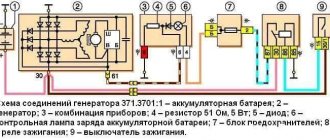
The generator is connected according to the diagram.
Price issue
The VAZ 21214 generator has good repairability, which allows you to significantly save money if worn or broken parts are replaced in a timely manner.
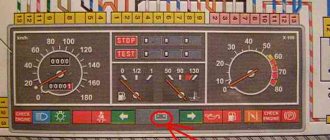
Location of fuse and relay blocks Lada 4×4
The main part of the fuses is located in the interior of the Lada 4×4 under the panel to the left of the steering column. Total 4 blocks:
1 — engine control system fuse box; 2 — windshield wiper relay; 3 — fuse blocks; 4 — relay block of the engine control system.
The fourth relay block is located above the gas pedal.
Video “Step-by-step instructions for replacing the generator on Niva 2121”
The video shows a step-by-step replacement of a generator set on a Niva (video author - Ivan Matieshin).
A week ago the diode bridge on my original gene flooded, I decided not to suffer - buy a new one, but for 80A. I've wanted it for a long time. Now this device is on the car)
What we needed to install generator 21214: Generator mounting bracket 21214-3701650 Compensating bushing for mounting generator 2110 complete with counter-shaped washer 2110-3701638 Generator mounting bolt 2110-3701376 with nut 2110-3701686 Additionally bolt M10×1.2 5×20 tension bar 21214-3701635 Bolt M8×25 with nut 2110-3701686 (like the lower mounting of the generator)
The signal lamp is blinking
Blinking of the battery indicator, as a rule, indicates problems in the brush assembly, as well as the occurrence of a short circuit in the “W” and “-” terminals of the voltage regulator. The brushes, in turn, can “freeze”, not reaching the rotor slip rings at low and medium speeds. You have already read how to fix them in our instructions.
However, the reason why charging on the Niva 2121, 2131, 21214 and 4×4 Urban disappeared is not always the above-mentioned components under the hood. In particular, the culprit of weak charging or its complete absence is an unmaintained battery with an insufficient volume of electrolyte or closed banks, loose and oxidized terminals, broken and melted wires.
Additional difficulties arise when dirt, dust, traces of fuel and lubricants, etc. accumulate on suspended equipment.
Replacing the power supply with your own hands
If any electrical circuit fails, the first thing you need to do is check the condition of the fuses and relays. This simple operation can be performed independently. The driver needs to know where the Niva Chevrolet fuse box is located and the purpose of the fuse links installed in it.
To protect electrical circuits on cars, fuses are used, located in a special mounting block. On a Chevrolet Niva VAZ 2123, this block is located inside the instrument panel, to the left of the plastic steering column cover.
In addition to the main unit, the Chevrolet Niva has an additional unit that is responsible for the operation of the car’s engine. This safety element is located in the passenger compartment and is located on the right side of the instrument panel behind the glove box.
The placement of blocks in the cabin is the same for cars of all years of manufacture.
The main blocks of machines are divided into two types - before 2009 and after. These devices are not interchangeable. The blocks behind the glove box are identical in design.
On a 2005 car, you can easily install a block from a 2011 car. The designation of the fuse rating is marked on the body; on the assembly itself there is a number of the fuse link and a pictogram of the purpose.
There are no fuse markings on the main unit cover.
If any electrical circuit in the vehicle fails, the condition of the fuse must be checked.
If it is necessary to replace parts, it should be taken into account that the VAZ 21214 fuses on the Niva injector belong to two different types:
- in the main block there are cylindrical inserts (inherited from the Zhiguli);
- and in the injection system blocks - modern, knife type.
Therefore, when you go on a trip, you need to take with you spare inserts of different types.
If, for example, a cigarette lighter fails on the road, you must:
- Turn off the ignition.
- Open the cover of the additional unit.
- Visually check the condition of the PR14 16 ampere fuse, which is responsible for the cigarette lighter circuit.
- Remove the burnt insert with your fingers and replace it with a spare one taken from the reserve socket PR15. It is prohibited to use homemade inserts, as they are not able to protect the circuit from overloads. The consequence of this may be overheating of the elements and fire.
- Check the functionality of the circuit. If the insert immediately burns out again, then the reason lies in damage to the wiring, which must be carefully checked.
The remaining fuses and relays on the VAZ 21214 are changed using a similar scheme.
In case of burnout or mechanical damage, it is necessary to repair the unit by replacing its components or the entire assembly.
To replace the main unit, follow these steps:
- Disconnect the battery from the on-board network.
- Remove the box cover and unscrew the two 8 mm nuts securing the block. Then you need to pull the box towards you and remove it from the fastening studs.
- Write down the markings and position of the wires on the old unit.
- Disconnect the cables from the plugs of the old unit and connect them in the same sequence on the new one.
- Check fuse ratings and wire installation.
- Secure the replaced block with nuts.
- Connect power to the on-board network and check the functionality of the circuits.
The photo shows some stages of dismantling the block.
Unscrewing fasteners
Removal from studs
Disconnecting the wiring plugs
Other fuse or relay blocks on the VAZ 21214 are replaced in the same way.
Below we will look at the process of replacing the power supply with your own hands. To replace, you will need a new power supply and a socket head set to “8”.
- First, open the hood and disconnect the battery.
- Now, under the instrument panel, find your power supplies. Using an “8” socket wrench, unscrew the two main nuts.
- Having done this, pry up the power supply and remove them from the studs.
- If you are replacing an old component with a new one, you must mark all the wires before doing so. Or take a new power supply unit and insert the wires from the old unit into it one by one. To remove the idle wires, pull them by their plugs.
- To check the functionality of the new power supply, reconnect the battery.
In addition to the main unit, the Chevrolet Niva has an additional unit that is responsible for the operation of the car’s engine. This safety element is located in the passenger compartment and is located on the right side of the instrument panel behind the glove box.
The placement of blocks in the cabin is the same for cars of all years of manufacture.
On a 2005 car, you can easily install a block from a 2011 car. The designation of the fuse rating is marked on the body; on the assembly itself there is a number of the fuse link and a pictogram of the purpose.
https://www.youtube.com/watch?v=SqqIBAU8osQ
There are no fuse markings on the main unit cover.
Identifying problems
Repairing the Niva Chevrolet generator can be useful only in certain cases, when replacing parts does not solve the problem. There are several signs after which it is worth checking the serviceability of the generator unit. They are the following:
- After starting the engine, the indicator light indicating the battery should go out. If after starting the engine the signal is still working, it means the battery is not being charged, the generator voltage is not enough to charge.
- When the engine was on, the headlights became dim. Although there is a charge from the battery, it is very small to maintain the normal operation of electrical devices in the car; the measuring instruments demonstrate low voltage properties - 12 V.
- There is noise coming from the motor, and points 1 and 2 are observed. The sounds may resemble the collision of iron surfaces or a whistle. Most likely, the bearing has broken and needs to be replaced.
Three-level voltage regulator Niva 21214
Forum post, original.
And we have a generator KZATE 9412.3701 produced by OJSC (form of organization of a public company; joint-stock company) “Plant named after A.M. Tarasov” (OJSC (form of organization of a public company; joint-stock company) “ZiT”) with low (for modern batteries) regulation voltage .
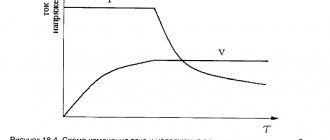
Voltage regulation is carried out through additional diodes specially created for this purpose, while the output voltage and regulation voltage are equal only in the absence of overload. When overload occurs and it grows, the difference between these values increases proportionally.
Since 2004, the AvtoVAZ assembly line began to receive the latest generators for cars 2110, 2123, equipped with a new generation of voltage regulators. Regulators of the latest standard determine the voltage at the power terminal B+ of the generator, as a result of which they have a very clear idea of the voltage on the battery/on board. networks. The regulation voltage is at a level that is rational for modern batteries. In addition, they have a number of other advantages, but this is not particularly important to us. So, we will install such a regulator in our generator.
First, we will need to purchase a voltage regulator for the generator 9402.3701-03 or 9402.3701-04. The 2nd one is the best choice, because its body is compatible with our brush assembly boot. I bought a voltage regulator 941.3702 manufactured by OJSC (form of organization of a public company; joint stock company) “Avtoelektronika”, Kaluga.
Then, instead of the usual terminals on the voltage regulator, you need to install the ones shown in the photo above. Be sure to use terminals with the same hole diameters as I indicated, otherwise this is fraught with a short circuit.
Management and tips for repairing Chevrolet cars
In general, the background is as follows - ever since the acquisition of the ShNG and after installing the State Speaker on-board computer on it, I monitored the low voltage readings on it. usually it did not exceed 13.5-13.6V without consumers. and with excessive consumption - heated mirrors, stove, high-beam headlights, and besides, when both fans were turned on at full strength - it was completely spinning around 12V, and from time to time it dropped to 11.5-11.8V, which caused nervous ( Nerve is a component of the nervous system)
BC squealing and, as a result, injury to my nervous system. when I got around to it, I tried to fight this with varying success - I replaced the standard 80A generator with a PRAMO 100A, measured the voltage on the battery - and the tester showed the applicable 14.2V, inspected the condition of the battery terminals - good, tightened the ground nuts on the controller (from there it takes readings my BC, and does not measure it itself), but the BC still showed a reduced voltage - and I began to blame the error in the readings of the BC itself. in general, I did not have one awareness of the problem and its solution at that time. and here fate made its stallion move)
Generator PRAMO 120A
The second solution was to install a prestigious thing on the new generator - a three-level voltage regulator. This prestigious crap has three levels of voltage regulation - high, medium and low. when consumption is high (in winter or when actively using a winch, for example, the highest level is set, during everyday civilian driving the average voltage level is set, and in hot summer conditions a low level is supposed to be set. In fact, in light of installing the winch, I was most interested in the upper one voltage level. As usual, I bought two straight away - one for installation, one for spare parts.
And so this prestigious thing is installed in this way - we have the back cover of the generator:
The rear part of the generator, so to speak
We remove it and get this nakedness - a diode bridge and a standard voltage regulator (RN) in the responsible helical joint:
Accordingly, we remove the standard launch vehicle from the joint by forcibly unscrewing two nuts and a screw, and remove it without restraint:
Replacing the belt
The belt is part of the transmission system between the engine and the generator, so its condition directly affects the operation of the generator set. During operation, it may break, which will stop the production of current in the machine. This should not be allowed, because if it is damaged, it must be replaced with a new one. To perform the replacement you will need the following tools:
- mount;
- screwdriver;
- a set of keys;
- jack to lift the car.
The replacement process is as follows:
- Disconnect the battery, then use a Phillips screwdriver to unscrew the crankshaft sensor fasteners.
- Loosen the belt fastening nut.
- Place the right side of the car under a jack, raise it, and engage 4th gear.
- We rotate the right wheel and first pull the belt off the pump pulley.
- We install the newest one in reverse order. The belt is located on the crankshaft pulley and only at the end is secured to the generator.
- We rotate the wheel so that the belt is tensioned and takes the required position.
- The fastening nut is tightened. The crankshaft sensor is installed.
- The belt is placed on the part in this order: crankshaft, then the upper tension roller, the lower right pulley, the lower tension roller, the pump, the generator.