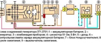
Connection diagram for generator 9412.3701 for Niva 21214i. Generator 9412.3701 is installed on a Niva 21214i with an injection engine. We present the electrical diagram of its connection.
Connection diagram diagram, connection of generator 9412.3701 for Niva 21214i
Notes and additions
— On a Niva 21213 car with a carburetor engine, a 371.3701 generator with a slightly different connection diagram is installed.
More articles on the Niva 21214i car
— Diagram of the engine control system (ECM) of the Niva 21214I
— Wires for the rear lights of the Niva 21213
The Niva has excellent cross-country ability and can compete with many modern foreign-made jeeps. However, due to such a significant drawback, most owners of these cars experience significant inconvenience, and therefore decide to improve this vehicle. This can be done by moving the generator upward.
The fact is that during testing of the VAZ-21213 for cross-country ability, sand, dirt, stones and water may enter the generator. However, there is another, quite significant drawback - coolant constantly gets onto the generator. This problem can be solved by using the above method. But how to do it right?
It should be understood that if you use your VAZ-21213 in most cases for trips around the city or on the highway, then there is no need to move the generator. But if the Niva is used for off-road driving, then you simply cannot do without it.
How to check if the battery is charging
Before looking for a fault in the charging circuit, it is necessary to find out whether this very undercharging actually exists. After all, the problem could be:
- in charge indication circuits;
- in a faulty battery.
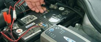
Healthy! To check, we use a DC voltmeter with a measurement limit of 20 V or a multimeter (tester). Both pointer and digital devices are suitable. The accuracy of both will be sufficient.
We connect a voltmeter or multimeter turned on in the DC voltage measurement mode to a limit of at least 20 V. We start the engine and raise its speed to 1,000 per minute. If the voltmeter shows a voltage in the range of 13.5-14.2 V, then the charging circuits are OK. The fault is with the charging indication elements that mislead us, or with the battery.
In the first case, we check the control circuits (their circuits and testing algorithm will be described below), in the second case, we test the battery using a load fork.
Charging circuit diagram and typical problems
Before finding out why charging disappeared on the Niva VAZ 2121, 21213, 21214 injector, 2131 and 2123 (aka LADA Niva and Niva Chevrolet), let’s look at the circuit diagrams of the charging circuit of these models and the principle of their operation. Otherwise, you will have to search at random, and this is a bad method.
VAZ 2121
Let's start with the oldest, because age must be respected. Let's take a look at the diagram below.
The numbers on the diagram indicate:
- - accumulator battery;
- – generator with built-in rectifier bridge;
- – relay-regulator;
- – ignition switch (lock);
- – fuses in the mounting block;
- – indicator lamp for lack of charging;
- – warning lamp relay.
When the ignition switch is turned on, the voltage from the battery through the fuse and the normally closed contacts of the voltage regulator relay is supplied to the generator excitation winding. The relay regulator does not operate yet, since the voltage in the on-board network is below the normal level for charging. At the same time, through the second fuse, the same voltage is supplied to the battery charging control unit, assembled on an electromagnetic relay with normally closed contacts.
Since the generator is not producing anything yet, there is nothing at its middle point of connection of the windings - all the rectifier diodes are locked, it seems to be hanging in the air. As a result, the control unit relay also does not work and the “no charging” lamp is on.
Now we start the engine, the generator begins to generate voltage, which is rectified, charges the battery and powers the on-board network. At this time, at the connection point of the windings, which is essentially the neutral wire, a low potential is established relative to the positive wire of the on-board network. The relay is activated and extinguishes the control lamp.
The voltage level from the generator is monitored by a relay regulator. As soon as it exceeds the critical value (14.2 V), the relay will operate, its contacts will open and a reduced voltage will be supplied to the excitation winding, which means the voltage in the on-board network will also decrease. It becomes below normal (13.5 V), the relay will release again, and the process will repeat.
VAZ 21213, 21214, 2131, 2123
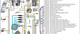
Now let's talk about other modifications of the Niva. All four remaining modifications of the car have the same charging circuit, shown in the figure below.
The numbers on the diagram indicate:
- - accumulator battery;
- – generator with built-in rectifier and relay regulator;
- – instrument cluster;
- – resistor;
- – diode switch;
- – indicator lamp for lack of charging;
- – fuse in the mounting block;
- – ignition relay;
- - egnition lock.
The schemes are very similar, but there are still differences. When the ignition is turned on, voltage from the battery is supplied to the ignition relay, and it is activated. The same voltage, through the normally closed contacts of the relay, is supplied to the charging control unit and from it to the relay-regulator as the initial bias of the excitation winding. An additional 12 V from the battery is supplied to the same relay-regulator built into the generator. In this case, the charging control lamp lights up, since its second output is connected to ground through an open diode and a small resistance (51 Ohms).
We start the engine, the generator rotates. The voltage it creates through additional decoupling diodes (on the left in the diagram) is supplied to the control output of the relay regulator. Based on this voltage, the relay-regulator controls the generator, changing the current in the excitation winding in one direction or another so that the voltage in the on-board network remains at the required level.
Important! The same voltage is applied to the cathode of the charge control diode. It locks and the light goes out.
Well, now let's talk about typical malfunctions of charging circuits and start, of course, with a false alarm that the charging control lamp can raise.
Characteristics of the standard generator
The main characteristics of the generator installed by the manufacturer in Niva 21214, 21213, 2121 will be considered using the example of generator type 9412.3701:
- current – 80A;
- voltage – 13.2 V,
- rotation is right.
The cost of standard models of electric generators is 5-7 thousand rubles. If the unit breaks down, it is possible to replace its components or completely replace it with the original or analogues. The prices of the most common ones are presented in the table.
| Analogue | vendor code | Cost, in rubles |
| Generator VAZ-2104-21073,21214 | 9412.3701-03 | 5900 |
| Generator VAZ-2104-21073,21214 | 372.3701-03/05 | 3800 |
| Generator VAZ 2121-21213,21214 | 9412.3701 | 5450 |
The table shows that in the process of replacing a generator on a Niva, you can give preference to a cheaper universal analogue.
Warning lamp
Why can this light be on while charging is in progress? In the VAZ 21213 there is only one reason - voltage is not supplied from the additional diodes to the control unit. This may be due to a broken wire running from the 61st terminal of the generator to the 6th terminal of the instrument combination assembly or contamination of the connecting blocks. We inspect the connections, ring the wire.
In VAZ 2121 there are not much more reasons:
- the warning lamp relay is faulty;
- voltage (negative) is not supplied from the generator to the control relay.
We remove the relay, apply 12 V to its winding from the battery and check whether it works and whether the contacts are disconnected. Well, problems with the absence of negative voltage are still the same broken wire going from the generator to the relay, or poor contact in the blocks of this circuit. We call and clean the terminals.
Expert opinion
Alexey Bartosh
Specialist in repair and maintenance of electrical equipment and industrial electronics.
Ask a Question
Once again, we draw your attention to the fact that the above malfunctions relate to the control unit and do not in any way affect the normal charging of the battery.
Nuances
When replacing a generator with a Niva 21213, 2121, 21214, a number of subtleties arise, and one of them is the location of the generator unit. It is located at the bottom of the engine compartment.
Actually, this is why problems arise with the operation of the structure: while driving, various contaminants get on the generator, and coolant drips. If you don’t want to constantly change the generator unit, it is recommended to move it upstairs.
To ensure that no problems arise during the operation of the car, it is important to monitor the condition of the car. First of all, it is recommended to regularly inspect the generator.
So, when the “battery” light blinks on the dashboard, if suspicious noises or creaking sounds occur, you should be wary and think that the generator is not working correctly.
Timely inspection will help to avoid unpleasant situations in the form of breakdowns of the constituent elements of the generator, and as a result, failure of entire electrical systems.
The belt has stretched or broken
The drive belt for the generator and water pump from the engine shaft does not break very often, but it stretches regularly. As a result, it begins to slip on the pulleys, the generator, especially under load (high beams plus air conditioning, etc.), does not develop the required speed, and the voltage at its output drops. As a result, the battery is undercharged and may even be discharged, helping the “exhausted” generator and feeding the on-board network with its energy.
Poor belt tension is characterized by a drop in the voltage of the on-board network and a peculiar whistle when the speed increases sharply, especially in wet weather. The problem is treated quite simply. Find the generator mounting bolt on the tension bar. We loosen it, use a pry bar to move the generator to normal belt tension and tighten the bolt.
Expert opinion
Alexey Bartosh
Specialist in repair and maintenance of electrical equipment and industrial electronics.
Ask a Question
Healthy! An over-tightened belt is just as bad as a loose one. It can tear, leaving you spending the night on the road, and will very quickly stretch again. So you shouldn’t tighten the belt “for future use”. Its tension force should be approximately the same as indicated in the diagram below.
Generator replacement
To repair or replace the generator, the car owner will have to remove the unit completely from the car or turn to professionals for work. If you still want to carry out the replacement yourself, then first you will need to prepare all the necessary tools:
- hammer;
- extension;
- keys to "10" and "19".
The procedure consists of the following sequence of actions:
- First, you will need to park the car in a place designated for inspection and repair. The car will also need to be secured using special wheel chocks. Finally, in order for the work to be carried out safely, you should disconnect the battery by disconnecting the terminals from it.
- After this, you need to remove the engine protection. It is attached to several bolts, and they must be unscrewed to get to the lowest bolt of the generator.
- After this, you will need to knock out the mounting bolt using a hammer. It is recommended to knock carefully so as not to damage the thread and to prevent the bolt from coming out in the opposite direction. A hammer is necessary, since a wrench or any other tool simply cannot handle a bolt.
- Next, you need to remove the bolt, swinging the generator from side to side. It is necessary to bolt in any case, as this makes it easier to remove the rod.
- The fourth step involves disconnecting the wiring. To do this, the power wires connected to the housing are disconnected from the unit. In this case, you can first disconnect the plug from the wires.
- Wires are also attached to the generator, tightened with a nut or bracket. In this case, the nuts must be unscrewed with a wrench, and then the loose wires must be pulled out.
- Finally, after disconnecting the wires, you can begin to unscrew the upper fastening element with the belt tensioner. For this you will also need a wrench, as well as a small extension cord.
- Disconnecting the fastener will allow you to remove the belt and alternator. Then you can start cleaning the vacated space with a brush and installing a new unit.
The structure is assembled in the reverse order; the entire procedure will take about two hours if you have all the necessary tools.
Additionally, it is worth noting that when everything is assembled, you will need to adjust the position of the generator using the tensioner. To do this, you need to unscrew the tensioner nut and tighten or loosen the belt, while observing the battery charge.
If the indicator returns to normal, then the selected tension is sufficient. There is no need to tighten the structure, as the generator bearing may fail. If the tension is insufficient, the generator will work intermittently, and this can also lead to breakdown.
Wiring and connections
One of the weakest points in the power supply circuit of the Niva (and any other car) is the connection of the power wire to the generator. The device is located low and is practically not protected from water and dirt. Even if this connection looks normal, it makes sense to disassemble it and inspect the contact point. We disassemble, inspect, clean if necessary, apply conductive lubricant, and assemble.
The next weak point is the connection of the negative wire of the battery to the engine. It is not located in the best place and is constantly dirty. As a result, the connection oxidizes and good contact is lost. We do the same thing: disassemble, clean, assemble.
It is also worth inspecting the terminals on the battery terminals. They may be oxidized (white coating) or loose. Clean, apply conductive lubricant, tighten.
Otherwise, the wiring and connections on the Niva behave quite correctly, but this does not mean that all this will last forever. Let's not be lazy, inspect the connections and wires. If necessary, we call.
Circuit breakers
The block of protective devices in Niva is a board on which disposable fuses are installed, containing a fuse inside. Each of them protects one or more electrical circuits from overvoltage.
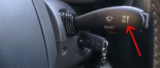
The unit is located in the cabin on the left side. Protective equipment is numbered. So, 1 is responsible for the work:
- windshield washer;
- stove fan;
- cleaners for all headlights;
- heating, wiper and washer for tailgate glass.
Fuse number 2 controls:
- turn signals, their operation in emergency mode, relay-breaker;
- reversing lamps;
- front windshield wipers;
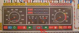
- dashboard indicators (coolant and oil level, carburetor valve position, parking brake);
- indicators of fuel reserve and antifreeze temperature
Problems with the generator
The most common malfunction of this unit is brush wear. At the initial stage, it manifests itself as periodic power surges. Symptom: the charging control lamp on the instrument panel blinks periodically - the battery charging indicator lamp, because charging is either there or not.
On a note! Often, brush failure occurs on the fly without any blinking. Yesterday everything worked, today the generator is not breathing.
On a VAZ 2121, the brush block is attached to the generator with one screw and connected to the relay-regulator using knife terminals, the condition of which is also very advisable to check.
In all other Niva car models, the brushes are made in one unit with a relay regulator. Car enthusiasts who consider themselves cool “brewed” call this block “chocolate”.
Remove the back cover of the generator. We disconnect the wires from the brushes (VAZ 2121) and “chocolate” (other models), take out the block and assess the condition of the brushes. They should not be burnt, crumbled at the edges or protrude from the body by less than 5 mm. If something is not right, we change it.
The next problem is wear on the slip rings of the generator rotor. Quite “adult” cars suffer from this disease. Remove the back cover from the generator and carefully inspect the rings.
If they are in bad condition, we replace them. You can see how to replace the slip ring block in the video below.
Replacing the Niva generator rotor slip ring block
The next malfunction is the failure of rectifier or additional diodes. In order to check them, you will have to disconnect all stator windings. They are connected to the diodes using screw lugs.
We unscrew, remove, and test each diode with a multimeter set to diode testing mode. In direct connection, the device should show several hundred Ohms, in reverse - an infinitely large resistance. If this is not the case, change the diodes. Since the semiconductors are pressed into metal plates in the form of a double horseshoe, which are radiators and conductors, you will have to change the entire group of diodes along with the “horseshoe”. Additional diodes can be changed one at a time using a soldering iron.
Expert opinion
Alexey Bartosh
Specialist in repair and maintenance of electrical equipment and industrial electronics.
Ask a Question
To check the diodes, it is enough to disconnect the windings; there is no need to unsolder additional diodes. They will not interfere with the continuity of the rectifier diodes and will themselves ring perfectly.
Well, the last malfunction is a break or breakdown of the stator or rotor windings. We remove the brushes, turn off the windings and check them with an ohmmeter for breaks and short circuits to the housing. In addition to a break and a short to the housing, an interturn short circuit is possible. Without special equipment, it is impossible to detect a short-circuited turn, so you will have to limit yourself to only estimating the resistance and the lack of connection with the generator housing.
In the video below you can see how the field winding is checked using an audio test.
Continuity of the generator excitation winding
Generator - device, characteristics, operation check
Start the engine, let it run for a few minutes, then, pressing the gas pedal, bring the crankshaft speed to 3000 rpm. Turn on the high beam headlights, heated rear window, and heater fan. Measure the voltage at the battery terminals, which should be above 13.2 V for generator 9412.3701 and 13.6 V for generator 371.3701. If this is not the case, the voltage regulator with the brush assembly, the generator windings are faulty (open or shorted) or the contact rings of the field winding are oxidized.To ensure that the voltage regulator is working properly, turn off all consumers except the high beam headlights and measure the voltage again. It should be between 13.2–14.7 V for the 9412.3701 generator and 13.6–14.6 V for the 371.3701 generator.
The removed generator voltage regulator 9412.3701 can be checked by connecting a lamp (1–5 W, 12 V) between the brushes, and a power source to the “D+” and “ground” terminals (DC only, “minus” to ground!) , initially with a voltage of 12 V, and then 15–16 V.
In the first case, the lamp should be on, in the second - not. If the lamp lights up in both cases, there is a breakdown in the regulator; if it doesn’t light up, there is a break or broken contact between the brushes and the regulator terminals. In both cases the regulator should be replaced. To check the generator regulator 371.3701, the current source should be connected to terminals “B” and “C” (“plus”) and “ground” (“minus”).
To check the valves of the rectifier unit, disconnect the wires from the battery, generator and from the voltage regulator terminal(s). Connect the “plus” of the battery through a lamp (1–5 W, 12 V) to the “B+” terminal of the generator 9412.3701 (to terminal “30” of the generator 371.3701), and the “minus” to its body. If the lamp is on, then there is a short circuit in both the block of “positive” and the block of “negative” valves.
To check the short circuit in the “positive” valves, connect the “plus” battery through a lamp to the “B+” terminal of the generator 9412.3701 (with the “30” terminal of the 371.3701 generator), and the “minus” - to the terminal of one of the phase windings of the stator. If the lamp is on, one or more positive valves are broken.
To check the short circuit in the “negative” valves, connect the “plus” of the battery through a lamp to the terminal of one of the phase windings of the stator, and the “minus” to the generator housing. If the lamp is on, one or more negative valves are broken or the stator windings are shorted to the generator housing. To prevent short-circuiting of the windings, remove the generator from the car and, having disconnected the windings from the voltage regulator and rectifier unit, check their short circuit to ground with a lamp or ohmmeter. The generator valves can also be checked with an ohmmeter without connecting the battery and test lamp.
The short circuit of additional diodes can be checked by connecting the “plus” of the battery through a lamp to terminal “D” of the generator 9412.3701 (to terminal “61” of the generator 371.3701), and the “minus” - to the terminal of one of the phase windings of the stator (to one of the mounting bolts of the rectifier block ). If the lamp is on, one or more additional diodes are broken.
A break in the main valves is determined by a sharp decrease in the output current (voltage drop under load). However, it can also be caused by an open or shorted circuit in the generator windings. A break in the additional valves can be determined by the low voltage on plug “D” of the generator 9412.3701 or plug “61” of the generator 371.3701 (below 14 V) at low and medium speed of the generator rotor.
The serviceability of each diode (main or additional) can only be determined with a removed rectifier unit using an ohmmeter or a test lamp. If the rectifier unit fails, it is recommended to replace it as an assembly. It is possible to replace individual valves, but the main valves will require repressing them in the holder - an operation that requires care and skill. The stator and rotor windings are checked with a special flaw detector or electronic oscilloscope - according to the shape of the voltage curves.
DIESEL NIVA GENERATOR
VAZ-21215-10 cars are equipped with a generator manufactured by Valeo, which is supplied complete with the engine. The voltage to excite the generator when the ignition is turned on is supplied to the “B-” terminal of the generator through control lamp 6. After starting the engine, no current passes through the control lamp and it does not light up. The “W” output of the generator is used to output a voltage signal to the electronic tachometer 4.
Valeo generator connection diagram
1 - battery; 2 - generator; 3 — instrument cluster; 4 — electronic tachometer; 5 - resistor 50 Ohm, 5 W; 6 - indicator lamp for battery discharge; 7 — fuse block; 8 - ignition relay; 9 — APS control unit; 10 - ignition switch