Hello everyone, I’m sitting here drinking beer, reading the feed and once again I see “I assembled it according to the diagram, it doesn’t work, help.”
I will try to explain how it works, why it is needed and how to connect it.
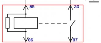
1. Here is the most common 4-pin relay
2. It has a diagram of the legs on the lid.
Pins 85 and 86 are the coil. Contact 30 - common contact Contact 87 - normally open contact At the bottom, the legs themselves have the same markings.
3. How to connect it correctly
From the decoding of the contacts it is clear that while the control signal (+) is not applied to the relay, then contact 30 and 87 are open.
4. Operating principle
At rest, i.e. when there is no power to the coil, contact 30 is open. When power is simultaneously supplied to contacts 85 and 86 (one contact is “plus” and the other is “minus”, no matter where it is, if there is no diode marking on the relay), the coil is “excited”, that is, it is triggered. Then pin 30 is connected to pin 87.
5.Why is it needed?
Relay is an electrical device (switch) designed to close and open various sections of electrical circuits for given changes in electrical or non-electrical input quantities. Types of relays may differ in the control signal and in design, we will not dwell on this. Moreover, all this is on the same Wikipedia. We only note that the most common: The relay is designed for switching large load currents. In other words, it is a switch, or even simpler - the principle of operation of a relay - with a small current (for example, a button signal) to turn on circuits with a large current. And a relay is used when the actuator (starter, generator, fan, heated mirrors, horn, etc.) consumes more current (up to 30-40 amperes).
Watch the video
Connecting a signal through a relay immediately solves many problems, the main one of which is electrolysis of wires due to unfavorable operating conditions of the vehicle (dirt, moisture).
VAZ 2107 - injector diagram (fuel injection control system)
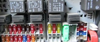
Most of the relays, as well as the voltage regulator, are located in the engine compartment.
Location of the VAZ 2106 relay in the engine compartment
If it fails, it is recommended to replace the relay assembly, since if the winding is burned out, or the relay contacts are severely burnt, it is difficult to properly restore its functionality.
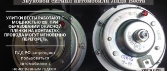
How to connect an audio signal
Having collected all the necessary elements, only now can you move on to the most important action - connection.
- The first step is how to connect a signal through a relay: remove the “-” terminal from the battery.
- Next, you need to remove the sound signal and install a relay in its place.
- Wire connection options
- A so-called “leech” is installed on the “+” wire that connected the sound signal. A wire approximately 15 cm long with male-female terminals is connected to it;
- If it is not possible to install a “leech”, you can strip the positive wire, then solder a piece of wire with a “mother” terminal to it. The soldering area must be sealed with insulating tape or pre-applied heat shrink.
- Next, the “+” wire must be connected to the relay. To do this, a wire with a newly formed process is connected to the 86th and 30th contacts.
- Let's move on, figuring out how to connect a signal to a VAZ or any other car. Now you need to connect the remaining negative wire to the relay. To do this, you need to use pin 85.
- An audio signal is connected to the remaining 87th contact of the relay.
- Last step: put the “-” on the battery.
General provisions and common cases of relay application
Car owners often equip their cars with additional equipment. For example, they install a winch, signal, powerful spotlight, alarm or, for example, an Orion taximeter
. All of these are high-amp devices. And passing the entire power signal through the power button of this equipment is not only impractical, but also dangerous.
First, you will need a high-amperage switching device. A button or toggle switch for 30–40 amperes will be of impressive size and may not fit into the interior. Secondly, if the button is of insufficient power or abnormal overloads occur in the network, this can lead to a fire. Therefore, it is recommended to install a relay.
There are several basic rules regarding how to connect a car relay to ensure its normal functioning:
- a block suitable for the parameters , the output wires of which are connected to the electrical circuit by soldering or by crimping into special detachable terminals.
- The maximum current consumption of the connected equipment should not exceed the values indicated on the relay.
- A fuse with a current value not exceeding that indicated on the relay must be installed in the supply circuit before entering the relay.
- The control circuit is connected through a resistor with the parameters necessary to create the rated current from which the relay coil operates.
Air signal connection
If you need to connect not an electric, but an airborne sound signal, the connection procedure will be almost the same as described above. The difference is that the wire from the relay does not go to the sound signal itself, but to the compressor (the engine that supplies air to the signal). And the pneumatic signal pipes are connected to the compressor through tubes.
When you press the horn, air from the compressor is supplied to the horns. With the help of a membrane installed in them, a sound signal is obtained.
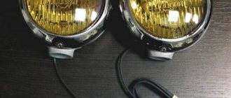
You can read about how to connect the headlights yourself in our article How to connect the headlights.
In my opinion, everything is already clear, and they have already written about this many times, but it may be useful to someone. For example, I recently gave a car I had made to a man, and over time his signal stopped working. You can’t travel all over Moscow for trifles, so he asked me to draw a diagram for him, I did it, but don’t disappear. I decided to post it publicly.
Description, I will try to use simple understandable language:
Two opposite contacts on the relay, numbered No. 86 and 85, are the so-called control contacts. If voltage is applied to them, the relay will close, and then direct voltage will flow through contacts No. 30-No. 87. Well, let’s say a contact that you need to break and briefly close, let’s say a signal. Why through a relay? Well, let’s take the interior button for example, the contacts on the buttons are weak and are not designed for direct load, and if you apply the plus from the battery through the button, say, to the starter, then after the first use the button will melt. Therefore, through the interior button we connect the control wires to the relay, and the direct plus to the consumer, in our case the signal. Thus, through a relay from the battery to the input (contact No. 87) and output (contact No. 30) to the consumer (Signal).
Turn signal relay pinout
During operation, the standard turn signal relay may fail and in this case it must be replaced. Incorrect operation of the device becomes obvious, especially when the indicator lamp stops lighting. The main cause of the malfunction is incomplete closing of the device.
In other cases, the relay begins to work unstably; the relay contacts close at different intervals. In some cases, the volume level of the sound accompanying the operation of the device is significantly reduced. This can create a serious problem on the road when the device turns on without the driver noticing due to accidental impacts while driving.
These shortcomings are eliminated by replacing the standard device with an electronic design. In this case, the turn relay is connected according to the standard diagram shown in the figure. Pin number 1 is positive, the second pin is used to connect to the rotation switch, the third is connected to the warning light, and the fourth is to ground.
All connections and contacts must be reliably insulated with electrical tape and cambric, which is a hollow plastic shell.
This eliminates possible short circuits with other conductors. Some disadvantages are created by the plastic housing of the electronic relay, which does not always fit into the normal position. However, home craftsmen quite easily overcome this difficulty and find the most optimal technical solution.
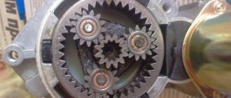
Starter wiring diagram
To understand the electrical part of the starter, let's first get acquainted with its circuit, try to figure out how it works, what elements it consists of, what task the individual elements of the circuit perform.
useful: Replacing the VAZ 2114 starter (step-by-step instructions)
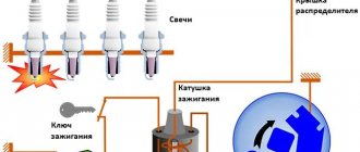
The driver inserts the key into the ignition switch (6), and turning the key starts the process. Electric current from the battery (2) is supplied to the generator (3) and to the electromagnetic relay installed on the starter (1). A running generator begins to generate electricity and supplies it to the tires of the mounting block (4), from where current is supplied to the starting auxiliary relay and ignition switch. The relay completes the circuit and supplies current to the solenoid relay coil, which in turn causes the starter to turn the bendix. And start the engine.
Where is the starter fuse located on the VAZ 2114?
As already mentioned, there is no fuse in the VAZ 2114 starter. Perhaps the error was caused by connecting the starter through the mounting block. But this device serves as a kind of distributor, a low-resistance conductor of electric current along the busbars. The second reason that forces car owners to look for where the starter fuse is located on the VAZ 2114 is the information that such a fuse is on the Priora. And it, together with the auxiliary relay, is located in the mounting block, which is unlike the VAZ Samara.
Signs of a malfunctioning retractor relay
A faulty traction relay can be identified by the following symptoms:
- when the ignition is turned on, there is no characteristic click accompanying the movement of the device’s armature to the rearmost position (the starter does not turn, the engine does not start);
- a click is heard, but the trigger does not fire;
- The relay is triggered, the starter starts the engine, but does not turn off.
If you turn on the ignition and find that the engine does not start, and one of the listed signs of a faulty starting device is present, try to find the problem yourself. In some cases, the damage may be on the surface, and it will only take a few minutes to fix it.
Checking work
Sometimes, despite more than obvious signs of breakage or wear of the retractor, in reality everything turns out to be wrong. The car may behave similarly with some other malfunctions.
Therefore, in order to figure out whether the relay works or not, and also who is the real culprit for the violation of the functionality of the system, we will conduct several checks.
- Check the starter. Turn the ignition key. The starter should begin to turn, and the relay should make a characteristic click. If the starter is not doing its job, replace it. Relyukha has nothing to do with it in this case.
- Check the solenoid relay. To do this, there are two copper bolts on the back cover. Two contacts are attached to them. If the starter starts turning, then your relay has definitely failed and needs to be replaced. In this case, you should not remove the starter, which will allow you to get more accurate test results.
- If you have removed the starter, the check is performed slightly differently : Connect the contact wire of the retractor relay to the positive terminal of the battery;
- The second contact connects the starter ground and the battery charger;
- When the contacts are placed on the relay terminals, the relay should turn on with a characteristic click;
- If the operation is too slow, uncharacteristic, check the condition of the contacts. They often burn out or oxidize.
How to connect a light relay to a VAZ 2106 - diagram and work procedure - Help for a car enthusiast
- this material is more expensive than, for example, acrylic;
- the main advantages of polycarbonate compared to acrylic are its higher impact resistance and increased light transmittance;
- polycarbonate has high heat resistance and resistance to precipitation;
- You can only service polycarbonate headlights with a soft sponge; you cannot use abrasive materials to care for them;
- Polycarbonate is approximately 2 times lighter than glass.
Information business website
The general meaning of connecting via a relay is the load on the switch that controls the installed equipment. At rest, i.e.
Separately, I would like to dwell on an important point, it concerns the use of DRLs in conjunction with high beam headlights. Without supplying voltage to the winding contacts, it is permanently closed to contact 87a.
The contact parameters and the maximum switching current are also indicated under the electrical diagram. But I don’t want to strain the wiring through the relay.
Usually a relay has 5 contacts, there are 4-pin and 7-pin, etc. Legislation Before practicing installing DRLs, I would like to dwell a little on the legal standards for installing DRLs, as well as the rules of their operation. Coil actuation voltage.
5 pin relay diagram
Electrical diagram
- Actually the headlights.
- Circuit breakers.
- Indicator of high beam headlights on the speedometer.
- Low beam relay.
- Mode switch.
- High beam relay.
- Generator.
- External lighting switch.
- Battery.
- Ignition.
Understeering's shifter
The steering column switch on the “six” is a three-lever switch (high beam, low beam and dimensions) and is attached with a clamp to the steering shaft bracket
Headlight relay
The VAZ 2106 car initially used headlight relays of the RS-527 type, which were later replaced by relays 113.3747–10. Both relays are located in the power unit compartment on the mudguard on the right in the direction of travel of the vehicle. In terms of their technical characteristics, the low and high beam relays are identical:
In normal condition, the headlight relay contacts are open: a closure occurs when the low or high beam is turned on using the steering column switch. Repairing relays when they fail is most often impractical: due to their low cost, it is easier to replace them with new ones.
Automatic headlight switching
Those drivers who do not trust their own memory perform a simple modification of the VAZ 2106 electrical circuit, as a result of which the car’s low beam turns on automatically
Mager73
https://www.drive2.ru/l/288230376151984970/
There are other options for automatically turning on the headlights, for example, through an oil pressure sensor, and any car enthusiast can choose the most suitable method for themselves.
Video: one of the ways to automate the inclusion of low beam on a VAZ 2106
Expert opinion
It-Technology, Electrical power and electronics specialist
Ask questions to the “Specialist for modernization of energy generation systems”
Connecting headlights and starter via a relay on a VAZ 2101 - FAQ, Articles on electrical equipment - Ukrainian Auto Club VAZ Obviously, the heat capacity of thin sections is less, which means that with the same current flowing, they heat up faster. Ask, I'm in touch!