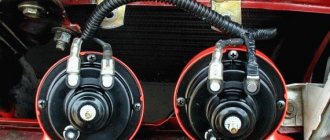
It was once 9. On it I limited myself to installing Zhiguli pipes, the red ones. It seemed to be normal. Then there was 10ka. The VAZ tweeter was a little confusing. I went to the electricians, they blew Volga pipes at her. With relay, as expected. There was generally an atmosphere, but there were also problems. The relays and horns were located behind the radiator grille, the horns pointing downwards. The sound was good, but contact was often lost due to water getting on the relay and pipes. The result is oxidation of contacts. Sometimes I had to disassemble, clean, bend... Fortunately, the grille on 10k was removed with two bolts.
I bought Vesta.
And I was a little saddened by the fact that she signaled in a disgustingly squeaky voice, like Oka some kind of thread or shokha. I rode for six months and endured this matter. And he even seemed embarrassed to honk) To prevent accidents, he beeped, of course. But to acquaintances, for example, he only waved his hand). And I also noticed that I’m stopping by our market. Well, there we have a type of “center”, a wide area, parking lots, cars, a market and the main shops ala “Magnit”. And people walk along the road as they please. And then you’re driving after someone, he’s rushing along the road, you honk - zero emotions. Either he doesn’t hear, or he just doesn’t care...
So I bought everything I needed
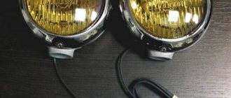
. Signal from the Volga, two pipes, two tones - high and low) (s302d and s303d, applicability GAZ, PAZ), four-contact relay 75.3777-10 (with screw fastening) (also suitable, it seems, 904.3747-10) and block for it, wires, terminals, corrugation, mounted fuse 25A, heat-shrinkable tubes. I couldn’t find brackets for the pipes, I cut them out myself from several layers of galvanized steel from an old window sill. Everything cost me about 1,500 rubles, of which 1,000 and a few kopecks were the signals themselves.
Started to use chemicals
. First I removed the bumper. I already talked about this www.drive2.ru/l/465834215582205001/ I received this:
Some people change the signal without removing the bumper
.
But it is quite difficult to find a place and it is not so convenient to run wires and attach signals. Moreover, I was also going to add a mesh to the radiator grille. That's why I removed the bumper, especially since everything is simple. Also, many people change signals directly
, that is, simply instead of standard ones. I didn’t take any chances, I decided to install a fuse and a relay - you never know. I don’t want everything to burn out). According to the passport, Vesta’s signal takes 5A, in reality it’s even less - about 3.5A. There are two Volgovsky ones, each takes 7-8A, and this is a total of 14-16A. And the circuit is 5A, it turns out. That's why I installed a relay. For those who don’t really understand electrics, my power goes through the relay directly from the battery (through the fuse) through a rather thick wire. And the signals come from the battery. And from the standard wiring there is only control of the relay so that it closes the main power contacts. This is the most painless option for wiring a car.
Now about the standard signal key
(on the steering wheel). I found on the Internet that it is a minus. On the standard signal tablet the plus is constant, and the minus is from the button. I checked. It's the other way around for me. The plus on the signal appears when the button is pressed. The plus on the standard one is a red wire with a white stripe. In general, I didn’t bother with the wiring, I took both the plus and minus from the standard signal, from the block, and to the light bulb, what exactly comes there. You can also connect a standard one, it will beep along with the Volgov ones, but I didn’t put on the block - it’s of little use. And I didn’t take it off - it’s hanging in reserve. If anything happens to the Volgov ones, I put on a block and the standard one works.
It was mandatory to remove the “-” terminal from the battery.
And he began to look for a place to listen. Found it, you can see it in the video. I liked the places behind the bumper, just below the headlights. Plus there are ready-made bolts for my brackets. It is not recommended to screw signals directly to the body. It will resonate and bounce into the body when the horn blows, so I had to make brackets. Cut it out and drilled holes. Everything is done by tweaking and tweaking)
Hung up the signals.
I screwed everything in and tightened it. There is no need to be fiddly here, there should be a good “mass”. The pipes were pointed inwards, towards each other. You can go down. The main thing is not upward, so that if water gets in, it doesn’t flow further into the pipe.
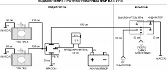
I did the wiring according to my same diagram.
I cut in a fuse from the battery to the relay, attached the relay to the body (in any convenient place closer to the battery, so as not to pull the power wire too far), and the wires to the pipes themselves. I insulated everything and put on corrugation. I stupidly tied it to the standard signal block and insulated it, I forgot the warranty. Yes, and you can carefully “minus” the battery and...
…checked.
EXCELLENT, Sounds like a bus. The video doesn't make as much difference as it does live. It's buzzing a lot. Pedestrians will not have a heart attack, but they will jump to the side and move away. I put everything back together. For more than six months everything has been working without any problems. I'm not afraid of a short circuit - if it happens, it will only be when you press the horn button on the steering wheel, and there is a fuse. There was never a problem. In general, DUDU) Pedestrians have begun to get out of the road more quickly, and no one is left unattended anymore. Participants in the movement can all hear me perfectly, even with their “super music and subs”) I signal without hesitation, in any case. Without fanaticism, of course, there is no need to scare everyone. He blew the whistle briefly and that was it, everyone heard it. The car’s status immediately increased in my eyes))) It already hums like a normal foreign car, although many foreign cars buzz worse. In my opinion (and hearing) one of my most useful improvements. Although everything is simple and inexpensive.
That's all, good luck everyone. If you have any questions, ask me, I’ll help you in any way I can. Although I am not an auto electrician myself, I did it without any problems. Bye PS Comparison of signals at the end of the video. Regular, then Volgovsky.
The warning device is located in front, to the right of the radiator. The new car owner may not like the native signal on the Lada Vesta.
Replacing a part is not difficult. The main thing is to choose the right model. The Lada Vesta has snail pipes. The installation is not entirely simple and you will have to tinker, but a motivated young driver can handle this job!
A powerful, loud ringing occurs due to pressure on the eardrums of the device. Two-tone volutes contain a relay. These versions of the horn allow you to choose a melody.
The sound device of the Lada Vesta is sold under article number 820110. The kit includes three parts:
Basic signal malfunctions of the Lada Vesta car
On Vesta’s car the signal does not work due to the following three main faults. This could be due to wiring or vibration:
- A broken sound signal on Vesta is not good. Russian traffic regulations prohibit using a car with a faulty horn. The main symptoms of a part failure are: complete absence of sound and its activation without driver participation. The reason why the horn does not work may be high voltage.
- Vesta snails operate with 12V power. When an oxide film forms on the contacts, the wires can instantly burn out. This type of horn cannot be repaired. To protect it from damage, regularly lubricate the contacts with specialized products. Make sure that the composition contains mineral oils, thickeners and stabilizers. Products based on graphite and finely ground copper powder have good electrical conductivity.
- Vibration from the motor quickly wears out Vesta's sound device. The fuse is the first to suffer. If it burns out, the signal will stop working. Checking the fuse will show whether it is to blame for the problem or whether the electrical circuit has burned out. Both parts can be replaced. Before doing this, find the reason for their combustion so that the replacement does not wear out prematurely.
The signal on the Lada Vesta does not work
According to traffic regulations, it is prohibited to operate a vehicle with a non-functioning sound signal. It serves to prevent emergency situations on the road when road users, for one reason or another, do not see each other. Therefore, a sudden failure of this device can play a cruel joke on the car owner. If such a malfunction is detected, do not put off repairing the horn for a long time. We will tell you about the main reasons for the breakdown, most of which you can handle on your own.
Manufacturers and prices of analogues
- Changing the signal on the West is easy. For convenience, it is recommended to remove the bumper. This way it will not interfere with connecting the wires. It is better to remove the bumper with the radiator.
- Remove the numbers and air receiver. The bumper is attached to the body with bolts in tens, twenties and thirty from below (four self-tapping screws). The bumper is secured at the edges with 20 screws (next to the wheels). Unscrew the remaining screws on top while holding the lid.
- Place the part on the floor, first laying it with a soft cloth. Do not place the bumper on the ground: small pebbles can scratch the paint.
It is not necessary to remove the standard Vesta horn. It can work together with the new one. This will increase energy consumption, so most car owners turn it off and leave it inactive in case the replacement breaks down. To connect it, it will be enough to connect the block.
Remove the negative terminal from the battery. Choose a location for new horns. They can be hung on old brackets from original Vesta parts. If the fasteners do not fit, buy new ones. It is better to inspect the fastenings before actual installation. Do not place the horn too close to the body. This will cause resonance: the wear of the part will increase, and the bell will be clearly audible in the cabin. Mark future holes for the brackets. Drill them. Screw the horns tightly. They should not dangle or shake when driving. Place the signal further from the bumper: moisture trapped in the membranes can short-circuit the contacts. If the installation is done correctly, you will not need to remove the bumper to remove the horns in the future.
The disk signal setting is different from the standard one. They can be mounted under the hood or placed next to the headlights. Connecting the signal to the wiring will be noticeably more difficult: it is important to insulate the wires well. They should not get wet. The horns located near the edge of the hood run the risk of burning out during rain.
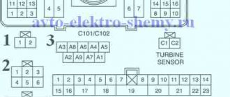
Power unit in the engine compartment
The mounting block itself is located near the battery (shown in the photo below). All electrical circuits in it are reliably protected from moisture and dust using a sealed cover equipped with special latches. This adds a little comfort when operating the car.
To open the specified cover, you need to press the two latches along the edges, which are shown by arrows in the photo below.
After the block is opened, many fuses and executive relays are revealed. To avoid confusion, we numbered them all in the photo below and added a description to each element in Table 1.
The circuits that the fuses protect are shown in Table 1.
In some car modifications, the horn is protected by fuse F78 instead of F73. And food is extra. equipment in the trunk is protected by fuse F55.
The relays that are located in this block are also summarized in Table 2:
How to connect the Volgovsky signal to Vesta
If you connect a signal from the Volga, it will differ from the standard wiring of a Lada Vesta car. Instructions are included with the horns. The diagram describes in detail the connection of wires. All charges are indicated by the symbols “+” and “-”.
- To replace the horn, install a fuse between the battery and the horn relay. The latter is better secured to the body. The parts should be located close so that the power wire does not have to be pulled too hard.
- Connect the wire to the pipes. Insulate them using corrugation.
- Secure everything with zip ties: wires that don’t “walk” under the hood will last longer.
- Remove the standard wiring by attaching it to the body: mortise clamps will do.
- Installing a Volga signal on a vesta takes the same amount of time as installing a standard snail signal. After connecting the wires, check the Volgov signal.
Standard signal - article number and price
The sound device of the Lada Vesta is sold under article number 820110. The kit includes three parts:
- two low-tone sound devices with article number 2110372102013,
- hex bolt for assembly - 7703602226
- nut - article number 7703033206.
The contents of the package allow you to install the horn immediately and do not require additional purchases. The average cost of Lada Vesta Cross snails is 450 rubles. They operate with a voltage of 12V. The standard horn is made of ABS plastic.
Pneumatic signal
Initially, an electromagnetic horn is installed in the car. Such pipes consist of an electromagnet, a membrane and a core. The sound occurs when the core rod presses on the membrane. This type of horn is most often chosen by manufacturers: they have a simple design. They are divided into:
Vesta has a fairly conventional sound signal from the factory, although this is an integral safety attribute. Let me clarify right away that I don’t prefer to honk at everyone, I only use the signal in situations where it can prevent an accident; for other cases, high beams are quite sufficient.
However, how to prevent an accident with such a sound signal, because you need to take into account that there are cars with good sound insulation or with good music, or both. I remember that many of my friends installed pneumatic sound signals, of course they sounded good, but still it’s not something, it looks too massive + questions may arise when undergoing maintenance. In order to do everything neatly, it was decided to follow the path trodden by many - to install the so-called Volgov signals.
Before buying, it is important to know the following information - there are at least two modifications that differ in sound, as well as price, weight and dimensions. The first have numbers 22.3721/221.3721 low and high tone, respectively, the second S302/S303D.
In terms of sound, many people like the latter more, they sound somehow more mature and smoother, at the same time louder, but you need to take into account that they are noticeably larger in size. These signals are produced by two companies - SOATE and LETS.
It is better to buy in trusted and large stores for spare parts for VAZ, GAZ, PAZ, as there are many counterfeits. The original signals must bear GOST, the Quality Control Department stamp, as well as bolts for a slotted screwdriver.
Let's return to Vesta. From the factory there is one two-tone signal to the left of the radiator. To install, you will need to remove the bumper, fortunately on Vesta this is done quite simply, there are a lot of instructions, we won’t dwell on this.
Replacing the sound signal on a Lada Vesta is a simple procedure that any owner should be able to perform. After all, driving without a properly working horn is a priori unsafe, and taking a car to a service station due to such a breakdown is an unreasonably large amount of time. However, replacement in the event of a malfunction is not the only need. Many people are simply not satisfied with the volume or tone of the sound signal, and they replace the standard Vesta components with alternative ones. Therefore, both of these paths need to be considered in more detail.
How to set up bluetooth on Vesta
Let's take a closer look at how to enable bluetooth on Vesta.
The Bluetooth connection algorithm in the Lada Vesta station wagon will be something like this. First of all, turn on the smartphone, find the Bluetooth function in it and switch it to operating mode. The next step is to turn on the car radio. When new equipment is found under the name Vesta, they connect to it. The factory password for Bluetooth from the manufacturer is 0000. After connecting the phone to the MMS for the first time, the password will not be needed in the future.
Replacing the standard sound signal in case of breakdown
First you need to prepare the car for work by putting the parking brake on and turning off the ignition. Then you need to lift the hood and, armed with a “10” key, disconnect the negative terminal from the battery. Then you should dismantle the front bumper, which is best done with an assistant, so as not to damage the paintwork on the bumper itself and on the wings of Vesta.
The figure shows the mounting location of the Vesta signal, its plug and the signal itself.
Once this is completed, all that remains is to disconnect the plug with the wires from the signal horn. Then you can dismantle the signal itself, the bracket of which is attached to the body with one nut. For dismantling you will need an extension, a wrench and a 13mm socket.
Removing and installing the front bumper requires an assistant.
Assembly is carried out in the reverse order - you need to secure the signal, inspect its operation, install the bumper with an assistant and tighten the terminal on the Vesta battery.
The main reasons for the sound signal failure
Most car owners do not often use the horn in everyday life. But if such a malfunction is detected, then in the case when the car is under warranty and the signal stops working, you can contact an official dealer. You can also fix the problem yourself.
Understeering's shifter
The most common cause of signal failure is the headlights being turned on. The culprit is the switch, .
It may lose contact. It is also noted that such a design cannot always withstand even the warranty period for the car. Since the entire bundle of wires passes along the axis of the switch, when the regulator is turned, the entire structure of the contacts rotates, as a result of which the contact itself disappears.
To correct the situation, you need to remove the lever. If you have some experience, this will not take much time.
- To remove the element, you will need to remove the cover from the steering column.
- Before doing this, you must disconnect the power from the battery.
- To remove the casing itself, you need to unscrew two screws.
- After removing the lever, it must be inspected visually. A visual inspection revealed a broken black wire.
- If there is mechanical damage or a broken wire, this can be immediately noticed. In the event that the wire is damaged, you can simply solder it in place.
The photo shows that a black wire has fallen out of the wire chip, just put it in place
After such repairs, all elements must be assembled in the reverse order of disassembly.
Circuit breakers
Location of fuses in the main unit
Also, the sound signal may not work if the fuse is blown. It is located in the mounting block in the car interior.
- horn fuse number in the diagram above
It should be remembered that Renault Logan also has two more small blocks located in the engine compartment. It is recommended to check them all to identify any blown fuses.
Alternative options
In this case, the possibilities are limited solely by the imagination of the Vesta owner. Most often, sound signals from the Volga are installed on the Lada, since their sound is much louder. But there are other ways. The most common options for such “modernization” are:
Installation of signals from Volga
It involves not only installing “shells” directly on Vesta, but also various options for connecting them. It is worth remembering that the sound signal from the Volga can be either old or new. However, they have no differences, except for a slight difference in tonality:
Sound pressure – 105-118 dB.
It is necessary to take into account that simply replacing the signals on Vesta will not work, because their current consumption is different. For Vesta this figure is 5A (passport data), although in reality it usually does not exceed 3.5A. Signals from the Volga consume 8A each, which gives a total of 16A. Therefore, for their installation it is necessary to use a 4-pin type relay. In particular, you can use relay 904.3747-10.
In addition, on Vesta, only one plug is supplied to the factory signal - “Plus” is permanent, since it supplies power to the fan, and “Minus” comes from the button on the steering wheel. Regarding the Volga signals, they only need “Plus”, because “Minus” goes directly through the metal mount to the body.
This mounting option will lead to vibration and ringing during signal operation. Brackets must be used.
It is also necessary to take into account the dimensions of the sound signals - the Volgov ones are larger than the standard ones on Vesta. Therefore, installation in factory locations is excluded. In addition, it is not advisable to mount them directly to the body, as this will lead to vibration, and the sound of resonating metal will be mixed with the horn. So the best solution would be to use a bracket. The advantage of this option is its low cost - a set of “Volgov” signals will cost about 1,000 rubles.
Installation of relays in the interior of Lada Vesta
This is done directly in the fuse box. To carry out the work you will need the following components:
For installation, it is best to use the free space in the fuse box, to which the wires from the contact relay, which is responsible for activating the signal on the steering wheel, are transferred. In the place that has become vacant, a wire from relay contact “87” is placed. Next, you will need to remove the wire from the 13th contact block and insert it into the 13th connector “87” of the relay contact.
Connection diagram for Volga signals on Lada Vesta.
To supply “Plus”, you will need to feed the wire to relay contact “30” from connector “Ш5-6”, using a jumper of contact “86”. In this case, you will have to insulate the wire in red-white or black-white color, since “Plus” always goes to it.
This method has a number of advantages:
However, if you have a complete lack of experience and knowledge in the field of car electrics, it is better to contact an auto electrician when installing a relay in the cabin.
Installation of a relay under the hood of Lada Vesta
Regarding the components, they are similar, but the list will need to be supplemented with a few more elements:
The installation of the beeps themselves is carried out in a convenient place, and the connection is made according to one of two schemes:
- Using “Plus” directly from the fuse block;
- Using “Plus” directly from the battery, using a separate fuse.
First connection option.
In general, the second option is preferable. The relay should be located in a place protected from moisture. In addition, it is recommended to first wrap this component in polyethylene or insulate it.
Second connection option.
The work is quite simple - you will need to dismantle the Vesta bumper and remove the factory signal, and then you can begin assembly. First, it is necessary to properly insulate the wires, and it is recommended to pass the wire that connects the signals through the corrugation so that it does not fray over time. Then you will need to fix the relay, after which you can put everything back together.
One of the options for fixing the relay under the hood of the Lada Vesta.
Combined option
This method involves retaining the standard Vesta beeps, but installing “Volgov” ones as additional ones. At the same time, combining 2 different tonalities will be a very original and specific move. Fixation is carried out in the same way as in previous cases, in any convenient place through a bracket. After which you will need to properly insulate all connections so that dirt and moisture do not get on them.
Scheme of combined signal connection for Lada Vesta.
Installation of other sound signals on Lada Vesta
It is not necessary to concentrate exclusively on “Volgov” signals, since you can use beeps from other manufacturers. There are a lot of options on the market from different brands that you can buy - MITSUBA HOS-04GL, Elephant CA-10100 12v, GMP France / 410-510Hz and others.
Signal MITSUBA HOS-04GL.
Their price varies from 3,000 to 10,000 rubles, although there are sets up to 28,000 rubles. Their installation is similar to the processes with signals from Volga.
An example of installing signals from the GMP brand on a Lada Vesta.
Installing a sound signal with a compressor on Lada Vesta
To fix it, you need a whole set of components:
The undoubted advantage of this type of signal is its power, which significantly exceeds that of Vesta’s standard beeps. The sound of some signals can be heard 1.5-2 km away! Installation and connection are simple, and largely repeat the procedures with conventional signals, except that all elements will need to be connected to each other.
However, this type of signal for Vesta also has a number of disadvantages:
Price – the cost of such kits is noticeably higher than regular ones. The average price tag for a high-quality signal starts from 30,000 rubles. and reaches 40,000 rubles. There are many options for similar products on the market. For example, Hadley KIT 964 (29,500 rubles), Hadley KIT 984 (40,000 rubles), etc. Of course, you can also purchase a budget product, which is much more affordable, but its durability is questionable, in addition, the sound is quite fast such a signal fades out and becomes indistinguishable from the regular signal on Vesta.
Need for maintenance - this type needs to be lubricated and other measures taken from time to time.
Response time - unlike standard Vesta devices, which work immediately, beeps with a compressor are activated with a slight delay, since it takes time to fill the receiver with air. In a critical situation, these seconds can make a difference.
The presence of a receiver in the kit causes a slight delay in operation.
Installation location – the kit includes plastic elements, which are recommended to be installed at a distance from heating elements to avoid cracking.
Dust and dirt protection - it is necessary for the suction port of the compressor. To do this, you can use either a special filter or a regular stocking.
Crystallization of moisture - during operation of the pneumatic signal, moisture condenses on its working surfaces. Consequently, in winter, before warming up and thawing, the signal may simply not work.
The need to preserve Vesta’s standard signals is a prerequisite for successful maintenance.
Combination of sound signal and light on Lada Vesta
A very effective way to highlight a car is when, when you press the horn, the high beams will light up, or when you blink the high beams, the signal will also go off. However, when the high beam is turned on, the signal will not be activated. There is no need to change the basic wiring, just do everything according to the diagram.
A diagram for connecting a signal to Vesta, in which the signal will be triggered simultaneously with the blinking of the high beam headlights.
More details about the Lada Vesta wiring, as well as connection diagrams, can be found in this file: shemy_chutov_provodov_lada_vesta
I traced them on metal and with the help of a grinder and such and such a mother made them. The brackets were attached with M8x30 screws to the bumper under the bumper (I removed the standard screws). We attach the sigals to the brackets with a nut and a lock washer (included) - all the mechanical parts are done, let's move on to the electrics. We cut off the standard signal and unscrew it, solder a sealed two-pin connector onto the cut wires,
we isolate it and hide it in a corrugation (Chinese connector from Aliexpress, also sold in auto stores). We make a harness from corrugated wires.
The principle is simple (I won’t draw a diagram, but if necessary, write), we use the wires that the manufacturer intended for the signal as controls for a four-pin relay. From the positive screw (in the electrical distribution box, under the hood on the driver's side), we pull the wire to the fuse, from the fuse to the power contact of the relay, and we connect the output from the relay to signals (from the positive screw to the relay and then the signals, a stranded wire with a cross-section of 1.5 was used). The peculiarity of the electrical wiring is that it is placed in an electrical distribution box
located under the hood on the driver's side, the fuse and relay are installed in their “standard” places.
To take the positive from the screw, use an 8 mm ring terminal,
(you need 6 mm, but the area for the terminal is very large and at 6 mm, the crimp of the terminal would fall under the clamping nut - there are elongated ring terminals, I looked for it and couldn’t find it). For fuse and relay contacts I used 4.8 mm Lyra contacts, they
They are standard and installed in blocks (I ordered terminal 505 in the online store). I crimped the terminals with a crimper purchased in China on aliexpress, profile SN-48B,
squeezes quite well. I used the empty sockets of the standard pads for the relay and fuse (they were just empty, I don’t know how you have them, comfort MM equipment). Now the only difference from the factory version of the electrics is the VAZ relay (Vesta has its own imported ones). I inserted the bus into the electrical distribution box from the headlight side, there is
a place for the wiring entry, covered with a plug. The contacts on the signals themselves are ordinary father - mother, I used two mothers. I don’t honk often myself, but I’ve already had to “honk” the horn a couple of times – quite decently.
Price tag: 1,000 ₽ Mileage: 6500 km
Mounting block Lada Vesta in the car interior
The mounting block is located in a familiar place - near the driver’s left foot. To access the relays and fuses:
- turn the plastic handles (3 pieces) holding the unit cover from below;
- remove the lock on the upper right side of the cover;
- Pull the bottom of the cover, disconnect its upper holders to the instrument panel and remove the unit cover.
1. From the car manual
Circuit breakers:
Relay
2. From a repair book
Fuse diagram (Fuse, Rating, Circuit, Purpose, Fuse type)
- F1 15A K15R Windshield washer mini
- F2 30A*1/5A*2 K15R Left steering column switch (not luxury/lux) mini
- F3 10A*1 Left high beam headlight (not luxury) mini
- F4 30A*1/5A*2 K30S Left steering column switch (not luxury/lux) mini
- F5 15A K15R Heated seats mini
- F6 7.5A*1 K30S Right side lights mini
- F7 10A*1 K30S Left side lights mini
- F8 5A*1 K30S Rear fog lights mini
- F9 3A Direction indicator (turn signals) in the right mini mirror
- F10 5A K15S AMT mini robotic gearbox selector
- F11 10A*1 Left low beam headlight (not luxury) mini
- F12 15A K30S BCM controller (turn signals) mini
- F13 10A K30S BCM controller (own power supply) mini
- F14 10A K30S Mini brake pedal switch off
- F15 5A BTP Power supply for D&O (rain and light sensor), mini headlight range control
- F16 5A BTP Mini brake pedal switch off
- F17 5A BTP Lighting (canopy) for the glove box, trunk, thresholds mini
- F18 3A Direction indicator (turn signals) in the left mini mirror
- F19 10A*1 Right low beam headlight (not luxury) mini
- F20 5A Heated exterior mirrors mini
- F21 15A K15S BU SNPB mini
- F22 5A K15S Gearbox (instrument cluster) mini
- F23 5A K30S Gearbox (instrument cluster) mini
- F24 5A ACC ERA GLONASS, radio mini
- F25 5A VTR Controller ESP9.1 mini
- F26 15A K30S Power supply for mini fuel pump module
- F27 5A K15S Power supply for parking sensors mini
- F28 5A K15S EURU controller (electric power steering) mini
- F29 10A*1/5A*2 K30S Power supply for mini trailer lighting
- F30 5A K15S Controller ERA GLONASS mini
- F31 5A K30S Controller ERA GLONASS mini
- F32 10A K15S Bus power supply K15M (engine compartment) mini
- F33 5A BTP Window control mini
- F34 5A VTR Power supply for steering angle sensor, mini steering wheel button block
- F35 5A BTP Switch block in the driver's door mini
- F36 15A K30S Radio, mini diagnostic connector
- F37 7.5A K30S Stop lamps right mini
- F38 7.5A K30S Stop lamps left mini
- F39 10A*1 K15R DRL (daytime running lights) not luxury mini
- F40 10A*1 K15R High beam headlight right (not luxury) mini
- F41 20A ACC 12V socket (power supply for additional devices), cigarette lighter JCase
- F42 20A K30S BCM controller (BTP bus power supply) JCase
- F43 20A K30S BCM controller (door locks) JCase
- F44 30A K30S Electric windows (ESP) JCase
- F45 30A K30S Interior heater fan (heater) JCase
- F46 30A*1 K15R Power supply for windshield wipers JCase
- F47 25A*2 K30S EMM controller (PDS, LBS, LGO)
- F48 30A*2 K30S EMM controller (window cleaning)
- F49 25A*2 K30S EMM controller (PTF, ZPTO, license plate)
- F50 25A*1 K30S EMM controller (LDS, PBS, PGO)
Relay diagram:
| Relay number (current, A) | Relay name |
| K1 (70A*1/50A*2), circuit K15R | Power supply for lighting and seat heating (not luxury/luxury) |
| K2 (30A) | Free |
| K3 (30A) | Heated rear window |
| K4 (30A) | Front windows |
| K5 (40A) | Interior heater fan |
| K6 (30A) | Rear window lifter |
| K7 (20A) | Fuel pump module |
| K8 (20A) | ACC (12V socket power supply) |
*1 — for Classic and Comfort trim levels
*2 - for Luxe trim levels
FakeHeader
Comments 39
The lyres fit into the mounting sockets under the contacts - in the empty spaces where you want to install a relay or fuse. I'll draw a diagram later.
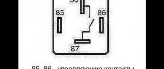
The relay has 4 contacts, divided into two pairs. The first pair is “low-current” - for closing and opening the relay. We connect the two wires that went to the signal (pins 85 and 86) in any order. The second pair is power, which will supply current to the signals. The wire from the ring terminal (with +) goes to the fuse contact (4.8 pin is inserted), from the fuse (4.8 pin is inserted) to the relay (4.8 pin is inserted) - any contact for relay 30 or 87, and from the remaining contact to the signal. The principle is that the wires are connected in pairs, two from the previous signal control the relay (85 and 86 on the relay). And the power wire from + to the fuse, from the fuse to the relay (let's say 30), and from the remaining (let's say 87) contact to the signal.
From the signal relay - wires to the relay control, plus from the red screw contact (on the right). The main principle.
I just don’t understand how the standard signal works without an additional relay and fuse? And why can’t you connect the Volgov signal to the standard translation and that’s it? The standard wire already has a plus. Why put a separate plus in the fuse box? Why do we need dances with a tambourine, relays, fuses, additional wiring, etc.?
The standard signal on Vesta does not sound at all respectable. Therefore, I decided to change it to a signal from the Volga. It got much better!
It was once 9. On it I limited myself to installing Zhiguli pipes, the red ones. It seemed to be normal. Then there was 10ka. The VAZ tweeter was a little confusing. I went to the electricians, they blew Volga pipes at her. With relay, as expected. There was generally an atmosphere, but there were also problems. The relays and horns were located behind the radiator grille, the horns pointing downwards. The sound was good, but contact was often lost due to water getting on the relay and pipes. The result is oxidation of contacts. Sometimes I had to disassemble, clean, bend... Fortunately, the grille on 10k was removed with two bolts.
I bought Vesta.
And I was a little saddened by the fact that she signaled in a disgustingly squeaky voice, like Oka some kind of thread or shokha. I rode for six months and endured this matter. And he even seemed embarrassed to honk) To prevent accidents, he beeped, of course. But to acquaintances, for example, he only waved his hand). And I also noticed that I’m stopping by our market. Well, there we have a type of “center”, a wide area, parking lots, cars, a market and the main shops ala “Magnit”. And people walk along the road as they please. And then you’re driving after someone, he’s rushing along the road, you honk - zero emotions. Either he doesn’t hear, or he just doesn’t care...
So I bought everything I needed
. Signal from the Volga, two pipes, two tones - high and low) (s302d and s303d, applicability GAZ, PAZ), four-contact relay 75.3777-10 (with screw fastening) (also suitable, it seems, 904.3747-10) and block for it, wires, terminals, corrugation, mounted fuse 25A, heat-shrinkable tubes. I couldn’t find brackets for the pipes, I cut them out myself from several layers of galvanized steel from an old window sill. Everything cost me about 1,500 rubles, of which 1,000 and a few kopecks were the signals themselves.
Started to use chemicals
. First I removed the bumper. I already talked about this www.drive2.ru/l/465834215582205001/ I received this:
Now about the standard signal key
(on the steering wheel). I found on the Internet that it is a minus. On the standard signal tablet the plus is constant, and the minus is from the button. I checked. It's the other way around for me. The plus on the signal appears when the button is pressed. The plus on the standard one is a red wire with a white stripe. In general, I didn’t bother with the wiring, I took both the plus and minus from the standard signal, from the block, and to the light bulb, what exactly comes there. You can also connect a standard one, it will beep along with the Volgov ones, but I didn’t put on the block - it’s of little use. And I didn’t take it off - it’s hanging in reserve. If anything happens to the Volgov ones, I put on a block and the standard one works.
It was mandatory to remove the “-” terminal from the battery.
And he began to look for a place to listen. Found it, you can see it in the video. I liked the places behind the bumper, just below the headlights. Plus there are ready-made bolts for my brackets. It is not recommended to screw signals directly to the body. It will resonate and bounce into the body when the horn blows, so I had to make brackets. Cut it out and drilled holes. Everything is done by tweaking and tweaking)
I did the wiring according to my same diagram.
I cut in a fuse from the battery to the relay, attached the relay to the body (in any convenient place closer to the battery, so as not to pull the power wire too far), and the wires to the pipes themselves. I insulated everything and put on corrugation. I stupidly tied it to the standard signal block and insulated it, I forgot the warranty. Yes, and you can carefully “minus” the battery and...
That's all, good luck everyone. If you have any questions, ask me, I’ll help you in any way I can. Although I am not an auto electrician myself, I did it without any problems. Bye PS Comparison of signals at the end of the video. Regular, then Volgovsky.
The Lada Vesta has two beeps. One signal is a warning signal, and the other is an alarm signal.
To replace or repair signals, you need to prepare the car for work.
Raise the hood and disconnect the negative terminal from the battery using a 10mm wrench.
In order to remove the signal signal, you need to remove the bumper, as described in the article “Removing and installing bumpers on a Lada Vesta car.”
After this, disconnect block 1, Figure 1, of the front wiring harness from sound signal device 2.
Using a 13mm socket, unscrew nut 3 securing the sound warning device to the car body and remove the sound warning device.
Install the sound signal device in the reverse order of removal.
The tightening torque of nut 3, Figure 1, fastening the sound signal device is 20…30 Nm (2…3 kgf.m).
After repairing or replacing the signal, we install the front bumper.