In order not to refer to the coff page every time, I will copy here the modification scheme and its original description in italics
with my additions and comments:
0. So, for starters, be sure to!
disconnect the ground wire from the battery. Our relays have contacts under constant voltage, and since all this will have to be done in an awkward position under the glove compartment and next to metal parts, you can easily make a short circuit.
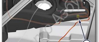
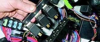
1. Remove the glove compartment lid
, having pulled out the two plastic axles and unhooked the limiting cables, unscrew the nut and remove the casing covering the brains. We get this picture.
2. Relays 6 and 8 are replaced with 5 contact ones.
We will do this later, at the end of the build.
3. Between leg 88 of relays 6 and 8, place a jumper.
A jumper between the NO contacts (88 according to the new circuit or in real life between contacts 87a) of our new relays. The wire must withstand at least 10 A. I got it like this:
4. On relay 8 we swap red 30 and pink black 87.
A small digression. The terminal in the standard relay block is held in place by a bent iron tendril (on the terminal itself) on one side and a plastic spring protrusion in the block itself on the other side. This differs from the factory block from many individual blocks sold in stores. In them, as a rule, contact is maintained only by the antenna on the terminal. Accordingly, in a regular block we bend the spring contact (from the connector side) with a thick needle or a narrow clock screwdriver and the terminal can be pulled out. This does not work with a standard block. In addition to pressing out the spring contact, you also need to use an awl or a narrow screwdriver to tighten the plastic contact of the block. Most often this is easier to do by inserting a screwdriver into the terminal from the wire side. If the contact does not pull out, do not use excessive force - you will simply break or tear off the terminal. Of course, it’s easier to use special pullers, but if you don’t have them, then you can get by with thin screwdrivers. I used these from a cell phone repair kit:
5. On relay 6, cut off the red 87 and connect it to ground.
We cut through the thick red wire (about three centimeters in length from the block). We isolate the part that goes into the wiring harness. We remove the terminal remaining in the block and splice it with a thick (no less than the thickness of the red wire) wire with a round terminal. The current on this wire can already exceed 25 amperes.
How does the Niva fan connection diagram described above work?
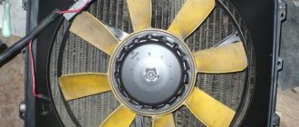
When the engine temperature reaches the low temperature sensor response threshold, the relay to which it is connected will operate.
In this case, the current from the fuse through the relay contacts will flow to the positive brush of the first fan. Then passing through the armature winding to the negative brush and through the contacts of the additional relay to the second fan motor. At the electric motor collectors there will be ½ of the on-board network voltage. This will lead to a reduction in speed by half, and accordingly the noise will decrease. If the engine temperature reaches the response threshold of the second sensor or the temperature at which the ECU fans turn on, the additional relay coils and the second fan relay will receive power. The movable contact of the additional relay will switch the wire from the fan motor to vehicle ground, at the same time the second fan relay will close. This will cause the fans to be switched in parallel.
“If you notice an error in the text, please highlight this place with the mouse and press CTRL+ENTER”
admin 05/09/2015
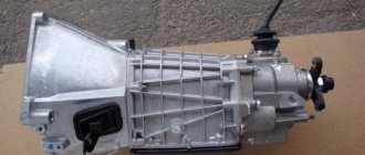
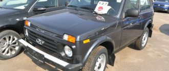
The VAZ-21214 engine cooling system is designed for off-road driving, that is, to operate for a long time at low speed and high revs. This causes the engine to become very hot. Therefore, the Nivas are equipped with a cooling radiator slightly larger than on the classics and two cooling fans.
In fact, the machines are operated mainly in urban environments, where the engine operates without overload and the operation of two fans to cool the radiator is practically not needed. In addition, when operating, the Niva cooling fan makes quite a bit of noise, which affects comfort.
Chevrolet Niva 2008, 80 l. With. — tuning
Cars for sale
Chevrolet Niva, 2015
Chevrolet Niva, 2010
Chevrolet Niva, 2015
Chevrolet Niva, 2013
Comments 44
Thank you! There was no need to think, I read it and did it!
You can use any diode there. I adapted it from an old Soviet TV; without it, Jackie Chan came to visit every day. Hmm... I didn’t even look at the year of publication