The ignition coil, which is located in the car, essentially converts the low voltage from the battery and generator into high voltage, to supply it individually to each spark plug. Roughly speaking, this is a miniature electrical transformer, the moment of failure of which is almost impossible to predict and repairs and diagnostics have to be carried out on the failed device. Below in our article we will tell you in detail how to check the ignition coil for a VAZ-2112 with your own hands.
The video describes in great detail the algorithm for checking the ignition coil on a VAZ-2112:
Checking and replacing the ignition coil on a VAZ 2112
The ignition coil of the VAZ 2112 engine is the main part of the car’s ignition system, which serves as a conventional low-voltage direct current converter, which comes from the battery or directly from the electric generator into high-voltage voltage for further supplying an electrical impulse to the spark plugs.
In today's article we will learn how to check the ignition module on an injection VAZ-2112 8 valve with our own hands, and also consider step-by-step instructions for replacing this car unit.
Purpose and design of the ignition coil of the VAZ 2112
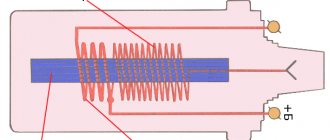
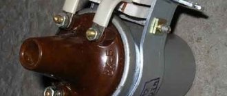
To create a pulse (spark) between the electrodes of the spark plug of the VAZ 2112 carburetor engine, a “standard”, classic or case coil was used for a non-contact ignition system (BSI), which is a high-voltage pulse step-up transformer with an open or closed magnetic circuit. Its use on “two-wheelers” continued until it was replaced by a two-spark (four-terminal) ignition coil (module) for 8-valve injection engines and an individual coil for power units with 16 valves.
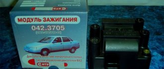
New ignition coil for VAZ 2112
Diagnostics of malfunctions of the VAZ 2112 housing ignition coil for BSZ, nomenclature number 3122.3705 or 8352.12, consists of measuring the resistance of its primary and secondary windings and comparing the obtained data with table values. The resistance of the primary winding of coil 3122.3705 should be 0.43 (±0.04) Ohm, the secondary winding - 4.08 (±0.4) kOhm. The resistance of the coil 8352.12 is respectively 0.42 (±0.05) Ohm and 5 (±1) kOhm. The insulation resistance to ground must be at least 50 MOhm.
If measurement results differ by more than tolerance values, the coil must be replaced. You need the VAZ 2112 ignition coil, with its relatively low price, it is quite reliable and its replacement is rather an exception to the rule.
Ignition module VAZ 2112
The ignition module (four-terminal coil) provides simultaneous sparking in two cylinders (the first and fourth or the second and third). It needs to be checked for serviceability if there is no spark on one or more spark plugs. It is checked using a stand that simulates various engine operating modes and an oscilloscope. Checking “in the field” consists of connecting a known working spark plug one by one to the tips of high-voltage wires, grounding it to ground and, turning the crankshaft with the starter, visually detecting spark formation on the electrodes of the “test” spark plug.
Design and principle of operation of the ignition module
Some old-school motorists call the modules double-spark coils, which makes sense. After all, the coil is the predecessor of the ignition module in the technical evolutionary chain. The module is a paired design consisting of two pairs of windings (primary and secondary) and a switch that alternately switches low-voltage current from one coil to another. In some models of double-spark coils, the commutator is structurally located outside the block.
The operation of the module is controlled from an electronic unit that collects and analyzes information from various working components of the engine. The block, unlike the classic coil, has 4 sockets for connecting high voltage wires going to the spark plugs. The pulse occurs in pairs, first at terminals 1 and 4, then 2 and 3.
That is, each of the built-in coils is responsible for the operation of two cylinders. A spark occurs simultaneously, as a pair.
This is what one of the ignition module models looks like. The connector for connecting incoming wires is visible at the top.
At the input, the ignition module has a connector with four terminals. Usually most models have markings opposite them. Pulses from the Hall sensor alternately arrive at contacts A and B, serving as a signal to switch the commutator from one primary winding to another. C and D – ground and power supply (12 V), respectively.
Version of the module on the 8-valve VAZ-2112
Two 8-valve engines of different volumes were installed on the twelve-wheeler - 1.5 and 1.6 liters. The ignition modules for these engines are different. The one and a half liter engine has a module with article number 2112-3705010, and the 1600 cc engine is equipped with a module 2111-3705010. A module for a 1.5 liter engine costs about 1500-2100, and the second one is 500 rubles cheaper.
Which is better?
SOATE devices manufactured in Stary Oskol have proven themselves to be the most reliable ignition modules.
Module structure
It consists of two ignition coils and two high-voltage switch switches. The coils are designed to create high-voltage pulses.
Possible causes of failure
The weak point of the ignition coils and modules is the secondary winding, which generates a high voltage pulse. A coil break or breakdown may occur in it. The following factors lead to this phenomenon:
- use of low-quality or unsuitable candles;
- operation with non-functioning high voltage wires;
- frequent attempts to check the spark.
The high-voltage pulse arising in the secondary winding must be realized (spent). If this does not happen (if the integrity of a high voltage wire is broken, for example), a high-energy electrical pulse seeks an outlet. He will find it, with a high degree of probability, in the thin secondary winding.
Often, a module malfunction occurs when the integrity of poor-quality factory soldering of wires going to the switch elements is violated. This happens from vibration. Also, the cause of non-working coils can be a banal contact failure in the incoming connector. Another factor leading to a malfunction of the ignition unit is often moisture that gets on the device during washing or driving in unusual conditions.
Malfunctions of ignition modules on VAZ-2112
If the VAZ 2112 engine starts running intermittently or does not start at all, the cause of the problem may be the ignition module.
Characteristic symptoms of a malfunction of the ignition module of the VAZ 2110:
- insufficient engine power,
- when accelerating the car jerks,
- either 1 and 4 or 2 and 3 do not work at the same time,
- the engine does not start.
It should be noted that on the VAZ-2112 one of the coils is responsible for the operation of cylinders 1 and 4, the second - for cylinders 2 and 3. If one ignition coil fails inside the monolithic block, two cylinders stop working at once.
To eliminate all other components of the ignition system, make sure that the spark plugs are in working order.
Installation of a new ignition module for VAZ 2112
To do this, unscrew them and check the spark on each of the spark plugs by cranking the engine with the starter and placing the spark plug with the high-voltage wire on the head so that the body (threaded part) of the spark plug touches the engine mass.
If there is no spark or it is weak, replace the spark plug with one that is known to work. If this does not lead to anything, check the high-voltage wires.
Thus, we will exclude spark plugs, caps and high-voltage wires from the list of non-working elements. Next we will check the ignition module.
Ways to independently check the ignition module
Some gasoline engines that are installed on modern domestic and imported cars are equipped with ignition modules, which are a pulsed high-voltage current source. There are situations when these devices fail, leading to a complete or partial loss of performance of the car engine. Ways to check for a malfunction in the ignition module in a garage are covered in this article.
Design and principle of operation of the ignition module
Some old-school motorists call the modules double-spark coils, which makes sense. After all, the coil is the predecessor of the ignition module in the technical evolutionary chain. The module is a paired design consisting of two pairs of windings (primary and secondary) and a switch that alternately switches low-voltage current from one coil to another. In some models of double-spark coils, the commutator is structurally located outside the block.
The operation of the module is controlled from an electronic unit that collects and analyzes information from various working components of the engine. The block, unlike the classic coil, has 4 sockets for connecting high voltage wires going to the spark plugs. The pulse occurs in pairs, first at terminals 1 and 4, then 2 and 3. That is, each of the built-in coils is responsible for the operation of two cylinders. A spark occurs simultaneously, as a pair.
At the input, the ignition module has a connector with four terminals. Usually most models have markings opposite them. Pulses from the Hall sensor alternately arrive at contacts A and B, serving as a signal to switch the commutator from one primary winding to another. C and D – ground and power supply (12 V), respectively.
Possible causes of failure
The weak point of the ignition coils and modules is the secondary winding, which generates a high voltage pulse. A coil break or breakdown may occur in it. The following factors lead to this phenomenon:
- use of low-quality or unsuitable candles;
- operation with non-functioning high voltage wires;
- frequent attempts to check the spark.
The high-voltage pulse arising in the secondary winding must be realized (spent). If this does not happen (if the integrity of a high voltage wire is broken, for example), a high-energy electrical pulse seeks an outlet. He will find it, with a high degree of probability, in the thin secondary winding.
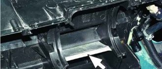
Removing and replacing the ignition coil
In order to replace the module (ignition coil) on a VAZ 2112, you must perform the following steps:
- Before starting work, be sure to disconnect the battery by disconnecting the “-” terminal from it. (How to de-energize a battery.
- Then, approaching the ignition coil, disconnect one single high-voltage wire from its central part.
- Next, use a wrench to remove the two side nuts that hold the ends of the wires in place on the side of the coil.
- Next, when the nuts are unscrewed, remove both side wires from the coil.
- And to complete the operation, unscrew the two side nuts securing the ignition coil itself to the bracket.
- And then remove the coil from the car engine.
Engine ignition coils 21124 (1.6i 16v) - check and replacement
To do the job you will need a multimeter.
1. We prepare the car for work (see “Preparing the car for maintenance and repair”).
2. Remove the decorative trim of the engine (see “Decorative trim of the engine - removal and installation”).
3. Press the lock of the wiring harness block.
While holding the latch in this position, disconnect the wire block from the ignition coil of the first cylinder.
4. Turning on the ignition, use a voltmeter to measure the voltage at terminal 3 of the wiring harness block (the numbering of the terminals is marked on the ignition coil).
5. Similarly, we check the supply voltage to the ignition coils of the second, third and fourth cylinders.
The voltage at the terminal must be at least 12 V. If the voltage does not reach the block or it is less than 12 V, then the battery is discharged, there is a malfunction in the power circuit, or the ECU is faulty.
When the voltage measurement is complete, turn off the ignition.
6. Using an ohmmeter, measure the resistance between the coil terminals. The electrical resistance between pins 1-3 should be close to zero (about 1 ohm). The resistance between pins 1-2 and 2-3 should be high (tend to infinity).
The faulty coil must be replaced.
10 mm socket wrench
Unscrew the bolt securing the ignition coil to the cylinder head cover.
8. Remove the ignition coil from the spark plug well.
Install the ignition coil in reverse order.
Source
Do-it-yourself installation of the VAZ 2112 ignition module
- Having picked up the new coil, first install it in its place by tightening the two nuts that secure it.
- Then place two wires on the sides of the coil and secure them with retaining nuts.
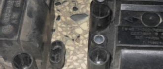
- When installing two side wires, pay attention to the markings that are marked on the sides of the ignition coil (see photo below). So this marking indicates which terminal of the coil should be connected to this or that wire. The blue wire must be connected to the “B” marking, and the red wire must be connected to the “K” marking!
- Then place the high-voltage wire on the central part of the ignition coil.
- And then install the negative terminal on the battery.
On old ignition coils, as a rule, instead of the letters “B” and “K”, the designations “-” and “+” are used, which means the same thing, but only in signs. The blue wire must be connected to the “-” sign, and the red wire must be connected to the “+” sign!
Symptoms of a problem
It is extremely rare for two built-in coils to fail at once, so it is more likely to be possible to start the engine with a faulty unit. However, even an inexperienced driver will immediately suspect something is wrong. The malfunction will appear as follows:
- unstable (floating) idle speed;
- the engine has difficulty picking up speed;
- characteristic sound of the engine (triple);
- jerking when accelerating (while moving).
Operating a car with such a breakdown is possible (you can drive to a garage or car service station), but it is not advisable unless absolutely necessary.
Similar signs of unstable engine operation are possible with a number of other ignition or fuel supply faults. To differentiate possible breakdowns, the performance of the ignition unit should be determined. It would be useful to check the contacts of the wires coming to the device, as well as their integrity.
How to check the ignition coil on a VAZ-2112 16 valves with your own hands
The ignition coil, which is located in the car, essentially converts the low voltage from the battery and generator into high voltage, to supply it individually to each spark plug. Roughly speaking, this is a miniature electrical transformer, the moment of failure of which is almost impossible to predict and repairs and diagnostics have to be carried out on the failed device. Below in our article we will tell you in detail how to check the ignition coil for a VAZ-2112 with your own hands.
Ignition coil device
It is known that on 8-valve engines an ignition module was used (module repair, diagnostics) with two channels and coils that are capable of transmitting a spark to a pair of spark plugs at once. However, on a 16-valve engine, the coils became individual for each spark plug.
Prices and articles
The ignition coil from the Russian manufacturer SOATE for the VAZ-2112 has article number 2112-3705010-12 and costs around 1,000 rubles . Analogs from Bosch can cost twice as much, but the quality of these parts is much higher. In any case, the choice is always yours.
Ignition coil from Bosch.
The process of checking all ignition coils on a VAZ-2112
The VAZ-2112 engine with 16 valves uses individual Bosch ignition coils and in order to check them, the following procedure must be followed:
- First of all, we remove each coil from its landing well.
The order of dismantling does not matter.
If it is damaged, replace it
Let's look at its correct location
Despite the fact that many people on the Internet talk about the impossibility of checking a coil with their own hands, it is possible to check it only by knowing their initial values, which are measured in ohms .
- In order not to make false measurements, first of all we check the internal resistance of the wires and the multimeter itself . To do this, switch the device to the OM position and connect the probes to each other. What value the multimeter gives is its internal resistance. The value can range from 0.0 to 0.3 ohm.
On the multimeter, a value of 00.3 Ohm is normal.
The value of 00.8 ohms is subtracted from the resistance of the multimeter and we get 00.5, which is the norm.
When the readings on the primary winding on all coils are correct and show their values, we proceed to checking the secondary winding.
- To do this, set the switch to 2000 kOhm mode.
- Next, we place the multimeter probe on the coil, observing the polarity, black to pin 2, which is located exactly in the middle of the connector, and the red probe to the spring, inside the rubber plug.
- Three-digit values will mean the coil is working properly, and infinity values will indicate its failure.
Such designations indicate the serviceability of the ignition coil.
The number “1” stands for infinity and indicates a faulty ignition coil.
Checking module power
Before testing the performance of the coils, you should make sure that a possible breakdown is not caused by a loss of power to the device. First, you need to try to simply restore contact by moving it several times or disconnecting/connecting the block of wires included in the connector. If such manipulation does not lead to improved engine performance, a tester (multimeter) is used to determine the quality of incoming pulses.
The block of wires is removed from the connector. On the block, each terminal (A, B, C, D) has a corresponding socket. Testing with the engine running is done as follows.
- The first contact of the tester is in socket D, the second is to ground. The multimeter switch position is 20 volts. If there is power, the tester shows 12 volts.
- The first contact is in socket C, the second is ground. Switch on ohmmeter (20 Ohm). Normally it shows less than 1 ohm, that is, the mass is normal.
- The first contact is in socket B, the second is ground. 20 volt switch. The norm is not less than 0.3 volts. If this is so, it means that a normal pulse is coming from the Hall sensor to position B.
- Contact A is checked similarly to the previous one.
If such a check shows the norm, you need to test the module. If not, look for the cause in the electrical circuit to the coil.