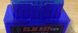
The VAZ 2114 diagnostic connector is required to connect the on-board computer. This device is in high demand among car enthusiasts, because it makes the operation of vehicles more convenient. There are many computers that will suit the VAZ. They can be connected to the car using this connector.
In most cases, there are instructions for using the device and connecting. But drivers often use used products that do not have the appropriate documentation. In this case, you will need information about where exactly the connector is located and how to install it.
Relay and fuse block diagrams for VAZ 2115
The Lada 2115 was first released in 1997 and finished production in 2012. Over such a long period of time, the electronic components of the car have changed significantly.
It is not surprising that modifications of the mounting blocks have changed more than once, and with them the fuses of the VAZ 2115. An old-style car with a carburetor required one installer in the engine compartment. With the advent of a new 8-valve injector, a second unit was needed, installed in the cabin under the dashboard. Some of the new relays were placed under the steering wheel during the 2007 and 2008 upgrades.
The design of the mounting block box has become more modern over time. To make life easier for drivers, a diagram was placed on the lid and tweezers were attached for replacing elements.
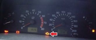
Symptoms of a knock sensor failure
Failure of an element is accompanied by the following symptoms:
- Jerking of the engine, which makes it seem as if the whole car is jerking.
- Engine power has decreased significantly.
- Fuel consumption began to increase.
- The engine temperature increases (data about this is reflected on the dashboard).
- The engine heats up very quickly, as evidenced by the data on the panel.
- There is a smell of gasoline in the cabin, but no signs of leaks were found.
- The on-board computer shows the following error codes: 0325, 0326, 0327.
Although sometimes these same symptoms can be caused by other malfunctions, most often the presence of several of them at the same time indicates a breakdown of the DD.
It is worth considering that problems in the operation of the sensor are not always caused directly by its malfunction. The cause of failures can be a break in the wires that connect the motor control unit and the ECU, corrosion, or even simple contamination of the part. All these nuances can be found out by examining the sensor and its surrounding elements.
Relay under the hood
The main one is the fuse box near the engine. The vast majority of fusible protective elements and almost all relays are located here. During the existence of the model, its modifications changed several times. The most common modern block was presented in 2008. In this release, the arrangement of individual elements has changed slightly and new ones have been added.
You can find the block in the engine compartment above all the devices in the engine compartment. It is protected by a cover that can be easily opened by pressing two latches.
DIY diagnostics of VAZ 2114 and 2115. Using a laptop. Recommendations from the experts
Every driver has access to do-it-yourself diagnostics of VAZ 2114 and 2115. It's quite easy to learn. Moreover, such a skill may be needed at any time. Engine errors can occur regularly. This may be due, for example, to low-quality fuel. You need to make sure of this. At the same time, visiting the service for the purpose of diagnostics is expensive and time-consuming. In this regard, it is a good idea to learn how to diagnose problems and do it at any convenient time. This will also significantly speed up the elimination of identified faults. In any case, the ability to correctly and quickly diagnose your car is a very useful skill. Many drivers find this very difficult and do not even try to carry out such work on their own. But in reality, anyone can do this...
Of course, this article will contain general rules of action, but with the help of them you will be able to inspect the entire car.
VAZ 2115 fuse diagram
The most common models are 3722010 (since 2004) and 21150 3722 010 10. The set of protective elements of electrical equipment in them is not very different from each other, but there are differences, and they are reflected in the decoding of the diagrams below.
The main mounting block under the hood of the car.
| Item no. | Power, A | What protects |
| 1 | 10 | Lamps for rear fog lights and PTF turn-on indicator |
| 1* | 10 | Headlight cleaner motor and relay (contacts). Headlight washer activation valve |
| 2 | 10 | Turn signals, breaker relay and hazard warning lamp |
| 3 | 7.5 | Interior lighting front, center, trunk Ignition switch Engine management system Brake lamps On-board computer |
| 3* | 7.5 | Rear lights (brake light) Body interior light |
| 4 | 20 | Cartridge for connecting a portable lamp Heated rear window (contacts) |
| 4* | 20 | Cigarette lighter Socket for portable lamp |
| 5 | 20 | Horn Cooling fan motor |
| 6 | 30 | Power windows Power relay (contacts) |
| 7 | 30 | Heater motor Windshield washer Headlight wiper motors (in operating mode) Cigarette lighter Glove compartment lamp Rear window heating relay (winding) |
| 7* | 30 | Headlight wiper motor Winding Heater motor Window washer Rear window wiper motor Windshield and rear window washer activation valve Cooling system fan activation Rear window heating relay coil Indicator lamp Glove compartment lighting |
| 8 | 7.5 | Right PTF |
| 8* | 7.5 | Left PTF |
| 9 | 7.5 | Left PTF |
| 9* | 7.5 | Right PTF |
| 10 | 7.5 | Left dimensions License plate lamps Engine compartment lamp Instrument lighting switch Illumination lamps for switches, instruments, cigarette lighter, ashtray, heater control levers Illumination panel for heater levers |
| 11 | 7.5 | Right dimensions |
| 12 | 7.5 | Right low headlight |
| 13 | 7.5 | Left |
| 14 | 7.5 | Left high beam headlight High beam indicator lamp |
| 15 | 7.5 | Right high beam |
| 16 | 15 | Turn signals, relay-breaker for turn signals and hazard warning lights (in turn signal mode) Reversing light lamps Lamp health monitoring relay On-board monitoring system display unit Instrument cluster Insufficient oil pressure lamp Parking brake activation lamp Brake fluid level lamp Battery low warning lamp Trip computer ( if installed) Generator field winding (in engine starting mode) |
| 17 | — | Reserve |
| 18 | — | Reserve |
| 19 | — | Reserve |
| 20 | — | Reserve |
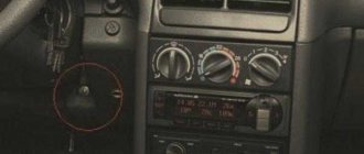
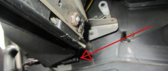
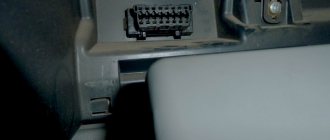
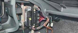
Where is the correct connector?
Most often it is located under the torpedo. By the way, it can be located on both the right and left sides. On certain models, the device is located near the steering column. Can be located to the left and below it. For cars that have a Europanel, the connector is located under the cigarette lighter.
Attention! The required connector can be covered with a decorative panel.
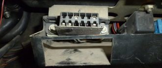
It is worth mentioning that two additional contacts, which are located on the diagnostic block of the VAZ 2114, are needed for the external air temperature sensor. After you make the connection, you will need to activate the K-line. It is necessary in order to transfer all important information to the device.
This is done as follows:
- The meter wire is connected to the second contact of the connector block.
- The second end is led to the diagnostic connector.
- The connection is made using the M-socket at the EURO 2 block, or to the seventh socket of the EURO 3 block.
- Connect the on-board computer and install it in the planned location.
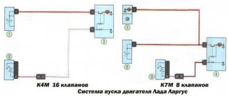
Why do you need an ignition relay?
This part was also installed on previous models of VAZ cars. However, on early versions of 2115 it may be absent. It is present in the starter circuit on VAZ-2115-01, 20, 21, 22 (injector, carburetor).
There are different names for this part: ignition relay, starter relay, starter interlock, ignition switch or lock relay, main relay.
But in any case, its purpose is the same - to facilitate engine starting and protect the starter from wear and damage. It turns off the power to the electric starter after starting the engine, limits the currents flowing through it, and protects against caking of contacts in the ignition switch or turning the key while the engine is running.
In addition, it ensures starting of the starter when the vehicle's electrical equipment is turned on and the battery is slightly discharged.
There are no fuses in the ignition circuit of cars of this model.
Thus, this inexpensive part protects you from expensive repairs and makes it easier to start the engine.
Diagnostics
After all additional work has been completed, you can proceed directly to diagnostics using a diagnostic scanner. In practice, it is easier to use a laptop with a diagnostic program installed instead. Before starting work, turn on the ignition. All work to assess the condition of the engine is carried out with the ignition on. Attention! It is forbidden to start the engine! We connect to the connector and launch the diagnostic program. Depending on its interface, you will first see either graphs with numbers or a list of indicators, again with numbers. From all this we can draw primary conclusions about the operation of the motor. Next, it “throws out” a list of detected errors. To decrypt them, you will have to look into the text file (usually it is downloaded along with the program). All errors that appear during engine operation are indicated there.
What changed
Despite the fact that the Pyatnashka car looks similar to its predecessor, model 21099, it received the following changes that are present in all trim levels:
- a new shape of the nose of the car with narrow headlights, corresponding to the global trend of the late 90s;
- a convenient trunk lid, which makes loading and unloading the luggage compartment of the “Fifteen” significantly easier;
- new, more comfortable steering wheel;
- a high instrument panel, which was called the “fourteenth”, because the VAZ 2114, although it appeared a little later than the “Fifteen”, became noticeably more popular;
- front power windows, which immediately made the car more comfortable;
- electric central locking and immobilizer, this also brought the car closer to the level of budget foreign cars;
- new original bumpers, thanks to which it is no longer possible to confuse 2115 with 21099;
- decorative moldings that make the appearance of the car more interesting;
- fog lights, thanks to which car owners no longer had to install them themselves;
- new injection engines that have proven themselves well in cars of the “Tenth” family.
Most of the changes affected the exterior and interior, but they brought the car much closer to the level of budget foreign cars, because the MacPherson strut at the front and the semi-rigid beam at the rear are still popular among manufacturers of inexpensive cars. Those owners who appreciated the driving performance, interesting appearance and low price left only positive reviews about the car, noting that it did not disgrace the Lada brand. The “Fifteenth” cannot compete off-road with cars equipped with all-wheel drive, but in the city it is much more convenient and comfortable.
Main unit
The main fuse and relay box is located in the rear part of the engine compartment, in the installation department, under a protective cover.
The current diagram for your vehicle can be printed on the back of the protective cover. Check your appointment!
Option 1
Scheme: 2114/ 2115 — 3722010, -3722020, -3722010-30, -3722010-38, -3722010-40, -3722010-48, -3722010-60, -3722010-68
Description of fuses
p, blockquote 10,0,0,0,0 —>
| F1 | 10A Rear fog lights, rear fog light indicator lamp |
| F2 | 10A Turn signals and turn signal breaker relay. Alarm system. Hazard warning lamp |
| F3 | 7.5A Interior and luggage compartment lighting systems (interior lamp, luggage compartment lamp, ignition key illumination). Stop lamp - brake signal, on-board computer backlight lamp. Engine control lamp |
| F4 | 20A Control of heated rear window. Portable lamp connection socket |
| F5 | 20A Relay for control and activation of the sound signal. Cooling system engine switch fuse and relay |
| F6 | 30A Control and relay for switching on electric glass lifts |
| F7 | 30A Electric motor control - heating system, interior heater, windshield washers, headlight cleaners. cigarette lighter , glove box lamp. Turn on the heated rear window. |
| F8 | 7.5A Turning on the right fog lamp |
| F9 | 7.5A Turning on the left fog lamp |
| F10 | 7.5A Side light of the left side body, indicator light for turning on the side lights (on the display), lamps for illuminating the license plate and engine compartment, illumination lamp for switches, cigarette lighter, heater control levers. Instrument lighting switch. |
| F11 | 7.5A Right side body marker light |
| F12 | 7.5A Front right low beam headlight |
| F13 | 7.5A Front left low beam headlight |
| F14 | 7.5A Front left high beam headlight. Light indicator lamp. |
| F15 | 7.5A Front right high beam lamp. |
| F16 | 15A Body turn signals, relay - turn signal and hazard warning light breaker. Control relay and reverse lamps, indicator lamps for the on-board instrument control system, lamps for oil pressure, handbrake activation, brake fluid level, battery charge. On-board computer, engine generator winding. |
| F17 - F20 | Spares |
Fuse number 7 at 30A is responsible for the operation of the cigarette lighter.
Relay purpose
p, blockquote 12,1,0,0,0 —>
- K1 - Relay for turning on headlight cleaners
- K2 - Relay interrupter for direction indicators and hazard warning lights
- K3 - Windshield wiper relay
- K4 - Relay for monitoring the health of stop lamps and side lights
- K5 - Window lift relay
- K6 - Horn relay
- K7 - Rear window heating relay
- K8 - High beam relay
- K9 - Relay for low beam headlights
Option 2
Scheme: 2114/ 2115 — 3722010, -3722020,
-3722010-08, -3722010-10, -3722010-18
Fuse designation
p, blockquote 15,0,0,0,0 —>
| F9 | 7.5A Right fog lamp. |
| F8 | 7.5A Left fog lamp. |
| F1 | 10A Headlight cleaners (at the moment of switching on). Relay for turning on headlight cleaners (contacts). Headlight washer activation valve. |
| F7 | 30A Headlight cleaners (in operating mode). Relay for turning on headlight cleaners (winding). The heater fan motor is the heater fuse. Window washer motor. Rear window wiper motor. Rear window washer timing relay. Valves for turning on the windshield and rear windows. Relay (winding) for turning on the electric fan of the engine cooling system. Relay (coil) for turning on the heated rear window. Rear window heating indicator lamp. Glove box lighting lamp. |
| F16 | 15A Direction indicators and relays - turn indicator and hazard warning switch (in turn indication mode). Turn signal indicator lamp. Rear lights (reversing lamps). Gearmotor and windshield wiper activation relay. Generator excitation winding (when starting the engine). Brake fluid level warning lamp. Oil pressure warning lamp. Carburetor air damper warning lamp. Parking brake warning lamp. "STOP" light display lamp. Coolant temperature gauge. Fuel level indicator with reserve indicator lamp. Voltmeter. |
| F3 | 10A Rear lights (brake lamps). Interior lighting. |
| F6 | 30A Electric windows for front doors. Relay for turning on electric windows. |
| F10 | 7.5A License plate lights. Engine compartment lamp. Instrument lighting lamps. Indicator lamp for external lighting. Heater lever illumination display. Cigarette lighter lamp. |
| F5 | 20A Electric motor of the engine cooling system fan, and its activation relay (contacts). Sound signal and relay for its activation. |
| F10 | 7.5A Left headlight (side light). Left rear light (side light). |
| F11 | 7.5A Right headlight (side light). Right rear light (side light). |
| F2 | 10A Turn signals and relays - hazard warning light interrupter (in hazard warning mode). Hazard warning lamp. |
| F4 | 20A Rear window heating element. Relay (contacts) for turning on the heated rear window. Plug socket for portable lamp. Cigarette lighter . |
| F15 | 7.5A Right headlight (high beam). |
| F14 | 7.5A Left headlight (high beam). Indicator lamp for turning on the high beam headlights. |
| F13 | 7.5A Left headlight (low beam). |
| F12 | 7.5A Right headlight (low beam). |
Fuse number 4 at 20A is responsible for the cigarette lighter.
p, blockquote 17,0,0,0,0 —>
- K1 - relay for turning on headlight cleaners
- K2 - relay-interrupter for direction indicators and hazard warning lights
- K3 - windshield wiper relay
- K4 - lamp health monitoring relay
- K5 - power window relay
- K6 - horn relay
- K7 - rear window heating relay
- K8 - headlight high beam relay
- K9 - relay for low beam headlights
Description of "brains"
The VAZ 2114 ECU is an on-board computer of the vehicle, designed to control the main systems of the car. The parameters of the control module affect both the functionality of certain regulators and the operation of the engine as a whole. That is, the importance of this system cannot be denied.
Controller Location
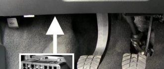
In VAZ 2114 and VAZ 2115 cars, the control module is installed under the center console of the car, in particular, in the middle, behind the panel with the radio. To get to the controller, you need to unscrew the latches on the side frame of the console. As for the connection, in Samar modifications with a one and a half liter engine, the mass of the ECU is taken from the power unit housing, from the fastening of the plugs located to the right of the cylinder head.
Location of the ECU in the Chetyrka
In cars equipped with 1.6- and 1.5-liter engines with a new type of ECU, the mass is taken from the welded stud. The pin itself is fixed on the metal body of the control panel near the floor tunnel, not far from the ashtray. During production, VAZ engineers, as a rule, do not securely fix this pin, so over time it can become loose, which will lead to the inoperability of some devices.
Design and principle of operation
The control unit of the electronic system operates in accordance with the indicators received from the sensors:
- speed;
- detonation;
- lambda probe;
- fuel injection phases;
- crankshaft position;
- throttle position;
- air flow meter;
- antifreeze temperature.
In accordance with the data received from these controllers, the control module controls the following systems:
- ignition;
- adsorber;
- injectors, as well as a fuel pump;
- ventilation and heating system;
- programs for diagnosing vehicle performance;
- idle speed regulator (video author - Evgeniy Vekhter).
As for the device, the control module structurally consists of the following components:
- RAM or random access memory. This module contains basic data about recently identified errors detected by the electronic system in the operation of various components. When the driver turns off the ignition, the RAM unit is updated, causing this data to disappear.
- PROM is the main element of the system; it contains the firmware of the control module. It should be noted that this memory block contains all the necessary data on the calibration of the “four” systems along with the general engine control algorithm. Unlike RAM, EPROM is a permanent memory, so the data stored in it is retained even after the ignition is turned off. If necessary, this module can be reconfigured, that is, reprogrammed, which can lead to improved power as well as vehicle dynamics.
- ERPZU - the primary function of this module is to protect the car. The EEPROM memory contains information from the anti-theft installation - passwords, as well as encoding of the main parameters. Starting the engine will only be possible if the EEPROM successfully checks with the data contained in the immobilizer memory.
Typical malfunctions: their symptoms and causes
What are the signs that indicate a faulty ECU:
- there are no control signals coming from actuators (IAC, flow meter, various sensors, etc.);
- there is no signal for interaction with the ignition system, fuel pump, injectors and other elements;
- when connecting a diagnostic tester, there will also be no connection with the electronic system;
- Burnt contacts and mechanical damage to the device may also be a sign.
What reasons contribute to the failure of the control device:
- electrical circuit shorted or broken;
- improper electrical repairs, during which errors were made, in particular, we are talking about installing or repairing an anti-theft system;
- lighting a dead battery from a car with the engine running;
- a breakdown of the unit can be caused by incorrect connection of the battery terminals - plus instead of minus and vice versa;
- disconnecting the battery contacts when the engine is running;
- moisture on the electronic system module board;
- mechanical damage to the device as a result of an accident (the author of the video about repairing the control module in a garage is the Auto Practice channel).
How to decipher the VIN code
Now that the body, engine and assembly number of the VAZ 2115 has been revealed, it is worth highlighting each value in the VIN code separately. A good example is the information plate, which provides all the basic information necessary for most cases. It is as follows:
Now, in order about each point:
- A special ID whose direct purpose is to match spare parts. The same number corresponds to the ID, which indicates the serial number of the vehicle.
- A meaning that indicates the vehicle's approval.
- A special identifier in which XTA is the code of the plant that produced the car; 211440 — vehicle model; 6 - year in which the vehicle was produced; 0000000 (last 7 digits) - body serial ID.
- Ordinal value of the installed motor model.
- Permissible possible load on the front axle.
- Permissible possible load on the rear axle.
- Identification IDs of configuration and execution options.
- Permissible vehicle weight.
- Permissible weight of the vehicle if it has a trailer.
Without this information, it is impossible to navigate the basic vehicle documentation.
Knowing where the VIN is located can help save several hours in the event of a quick inspection or sale of the car. That is why it is worth spending a little time to find the VAZ 2115 engine number - this will help prevent the occurrence of unfavorable situations.
Final processing
Primer, anti-corrosion treatment, installation of new sound insulation and installation of the interior with electrical connections are the final stage of work on the bottom. For external treatment, you will need bitumen mastic or anticorrosive Body 930. The product has a budget cost and is highly resistant. The mastic forms a dense but elastic protective layer that does not allow moisture to pass through and protects the iron. Final work step by step:
- Clean weld seams.
- Treat welding areas with a primer containing zinc.
- Cover the inner surface with mastic and install new sound insulation.
Rotten metal destroys the skimmer sheets in 3-5 months, so if the car needs the bottom to be overcooked, the sound insulation definitely needs to be changed.
- Treat the outer part of the bottom with bitumen anticorrosive. You can use paraffin aerosols; it is convenient to reach the hidden cavities of the bottom with an anticorrosive agent.
During operation, during routine inspection, it is recommended to periodically remove the plugs in the parts and pour the oil composition into the internal pockets.
- Install interior, doors. Connect the electrical.