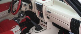
On cars of the “tenth” family, a one-piece plastic “dashboard” is used, which includes control indicators, climate control and air ducts. Dismantling and disassembling the structure is necessary in cases where the instrument panel of the VAZ 2110 does not work, as well as for installing additional equipment and sound insulation.
The device of the instrument panel on the VAZ 2110
The term “instrument panel” on cars refers to a block of warning lamps and indicators located in front of the driver. The correct name of the part is the shield, which is installed in a plastic panel called the dashboard.
The instrument panel on the VAZ 2110 includes:
- a device for determining the speed of movement - a speedometer;
- speed meter - tachometer;
- indicators of coolant temperature and fuel level in the tank;
- control indicator lamps equipped with yellow, orange, green, blue and red filters;
- lighting system (6 separate lamps);
- installation location of the warning lamp.
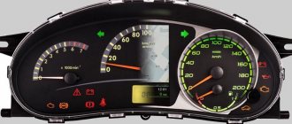
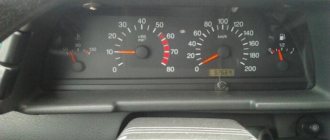
On VAZ 2110 cars it is possible to see several options for instrument combinations:
- The first releases used an electromechanical version of the panel with serial number 2110-3801010. Externally, the device is easily identified by a mechanical odometer mounted on the speedometer scale. Its drive is made from an electric motor, the rest of the indicators operate on a magnetic principle. On the back of the shield there are two connection blocks located at right angles.
- Later, an electronic version of the dashboard appeared, equipped with a liquid crystal display on the bottom of the speedometer. There are “gauges” with a “suction” indicator (which was not installed on the VAZ 2110 with such a panel from the factory) or with an airbag lamp in the same place. There may be cars with a double display window - under the tachometer and speedometer.
- A very rare variant of the instrument cluster is designed for the VAZ 21106, equipped with a 2.0-liter Opel engine. The part number is 21106-3801010 and features an extended speed measurement range (up to 240 km/h) and an additional liquid crystal display on the bottom of the tachometer.
- On the latest versions of the VAZ 2110, a shield began to be used, unified with the 2118 Kalina car (model 1118-3801010), differing in the layout of the scales. Such a part is called a “new sample” panel among its owners. The device is installed in a modified type dashboard.
Depending on the manufacturer and date of assembly, there are different designs for the VAZ-2110 instrument clusters. It is possible to digitize the tachometer in hundreds or thousands of revolutions, write technical information on the scale, etc.
Nuances of work
However, these pinout diagrams for the VAZ 2110 are, so to speak, basic, mostly the same, but there are also differences in color markings (especially by manufacturer). Therefore, you need to either use the instruction manual that came specifically with your car, or, armed with a marker and self-adhesive labels, “write everything out” in detail and not get confused when installing a new instrument panel.
Connecting wires to the VDO panel on a VAZ 2110
Connecting wires to the “Schetmash” panel in Kursk on a VAZ 2110
Connecting wires to the “AP” panel in Vladimir on a VAZ 2110
Connecting wires to the panel from the Kalina car to the VAZ 2110
During subsequent assembly, there will probably be a lot of devices that are not taken into account here, and, taking into account modern realities, many car owners plan to install them on the updated dashboard.
Instrument panel pinout
The instrument cluster is connected to the vehicle's on-board network using plugs located on the rear wall. The connectors are made of white plastic (indicated as X1 in the diagrams) and red (X2 in the diagrams). Depending on the manufacturer, the pinout of the plugs is different. This point should be taken into account when performing repairs.
Placement of elements on the rear wall of the shield
- 1 — fuel remaining lamp;
- 2 — panel illumination;
- 3 — right turn indicator;
- 4 — left turn indicator;
- 5 — white block X1;
- 6 — coolant temperature indicator;
- 7 — lamp for side lights;
- 8 — indicator of the switched on “suction”;
- 9 — control lamp for engine oil pressure;
- 10 — indicator of the applied parking brake;
- 11 — indicator of lack of battery charging;
- 12 — tachometer;
- 13 — Check Engine indicator;
- 14 — speedometer and red block X2;
- 15 — lamp for emergency brake fluid level drop;
- 16 — operation of external emergency signaling with turn signals;
- 17 — high beam indicator;
- 18 - a device that displays the fuel level in the tank.
Purpose of wires in the white plug of old-style combinations. The pin positions of the block are indicated in the diagram above.
| Pin number | Purpose | VDO wire color | Wire color Schetmash | AP wire color |
| 1 | Mass signal | Black | Black | Black |
| 2 | Tachometer from the engine control unit | Brown-red | Brown-red | Brown-red |
| 3 | Tachometer from ignition coil | Yellow | Yellow | Yellow |
| 4 | Constant positive supply (via fuse) | Red-blue | White-red | Red-blue |
| 5 | Liquid temperature signal | Green-white | Green-white | Green-white |
| 6 | Side lights (via fuse) | Yellow-black | Brown (2 pcs.) | Yellow-black |
| 7 | Choke indicator | Not used | Not used | Not used |
| 8 | Check Engine Light | White-red | White-red | White-red |
| 9 | Positive power supply (via fuse) | Orange (2 pcs.) | Blue | Orange (2 pcs.) |
| 10 | Likewise | Orange (2 pcs.) | Orange | Orange (2 pcs.) |
| 11 | Parking brake indicator | Brown-blue (2 pcs.) | Brown blue | Brown-blue (2 pcs.) |
| 12 | Generator terminal D | Brown-white | Brown-white | Brown-white |
| 13 | Signal from oil pressure sensor | Gray blue | Gray blue | Gray blue |
Purpose of wires in the red plug of old-style instrument clusters.
| Pin number | Purpose | VDO wire color | Wire color Schetmash | AP wire color |
| 1 | Outdoor air temperature sensor | Blue-red | Blue-red | Blue-red |
| 2 | Positive power supply (via fuse) | Orange | Orange | Orange |
| 3 | Negative signal | Black (2 pcs.) | Black | Black (2 pcs.) |
| 4 | Instrument lighting control | White | White | White |
| 5 | Right turn indicator | Blue | Blue (2 pcs.) | Blue |
| 6 | Same for left | Blue-black | Blue-black (2 pcs.) | Blue-black |
| 7 | Signal from brake fluid level sensor | Pink blue | Pink blue | Pink blue |
| 8 | Communication channel with the trip computer | Brown | Brown | Brown |
| 9 | Signal from vehicle speed sensor | Grey | Gray and yellow | Grey |
| 10 | Signal from fuel level sensor | Pink | Pink | Pink |
| 11 | High beam protection (fuse) | Green-black (2 pcs.) | Green-black | Green-black (2 pcs.) |
| 12 | Signal from alarm relay | Blue-white | Not used | Blue-white |
| 13 | Ignition switch control | White | Red | Red |
The pinout of the new panel is distinguished by the use of a single block with 32 contacts, some of which are not used.
| Pin number | Purpose | Note |
| 1 | Electric power steering | When installed on a VAZ 2110 it is not used |
| 2 | Alarm | — |
| 3 | Oil pressure | — |
| 4 | Hand brake | — |
| 5 | Standard immobilizer | When installed on a VAZ 2110 it is not used |
| 6 | Airbags | When installed on a VAZ 2110 it is not used |
| 7 | Side lighting | — |
| 8 | Right turn indicators | — |
| 9 | Left turn indicators | — |
| 10 | The engine control unit | — |
| 11 | Pad wear sensor | When installed on a VAZ 2110 it is not used |
| 12 | Seat belt indicator | When installed on a VAZ 2110 it is not used |
| 13 | traction control system | — |
| 14 | Controlling the on-board computer from the steering column switch | — |
| 15 | Brake fluid level sensor | — |
| 16 | ABS unit | — |
| 17 | High beam switch | — |
| 18 | Adjusting the backlight brightness | — |
| 19 | Negative power | — |
| 20 | Terminal "30" | — |
| 21 | Terminal "15" | — |
| 22 | Fuel consumption signal | — |
| 23 | Switching the computer menu forward | — |
| 24 | Switching the computer menu back | — |
| 25 | Negative external temperature | — |
| 26 | Positive external temperature | — |
| 27 | Fuel level sensor | — |
| 28 | Speed sensor | — |
| 29 | Engine temperature sensor | — |
| 30 | Low voltage tachometer signal | — |
| 31 | Diagnostic channel | When installed on a VAZ 2110 it is not used |
| 32 | Terminal L on the relay regulator | — |
Noise Removal
Basically, the panel rattles both due to improper installation and because the three parts that make it up touch each other, which causes creaks and rattles in the cabin.
That is why sound insulation is necessary, which the manufacturers did not take care of properly, and it is up to the owner to finalize it. Modelin can be used as sound insulation. They can paste over:
- All places where three parts of the panel touch;
- Those parts of the panel where it comes into contact with the radio, on-board computer, etc.;
- All bolt holes are also covered with modelling. It won’t hurt to screw them in, but there will be additional sound insulation, as well as protection against heat loss;
- Sides of the glove compartment;
- "Black box" in those places where it comes into contact with the panel.
Sources
- vazweb.ru/desyatka/salon/torpeda.html
- drive2.com/l/525053636976313571/
- drive2.ru/l/8335986/
- drive2.ru/l/452409453484966614/
What problems can arise with the instrument panel on the VAZ 2110?
The reasons why the instrument cluster stopped working are divided into two types:
- incorrect operation of the backlight or part of the indicators;
- complete shutdown of the panel.
Instrument panel backlight does not light up
Several light bulbs are used to illuminate the combination. A darkened section indicates one or two burnt out bulbs. If the backlight fails completely, you should check the fuse responsible for the power circuit. It is located in the cabin block in the first place on the left in the top row, and has a nominal value of 5A.
The cause of the indicators not working may be problems in the electronics. So, a malfunction in the engine controller is a possible reason for the failure of the Check Engine lamp.
If, in the event of a complete failure of the instrument lighting on a VAZ 2110, the rear license plate lighting lamps and the left side side lights stop working, all these symptoms indicate a failure of the fuse link.
Complete node failure
Complete failure of the instrument cluster means turning off the dial indicators, warning lamps, and display. The main cause of the malfunction is the blown fuse located in the cabin unit. The 10 A insert is installed second from the right in the bottom row.
You can verify that the fuse has failed by looking at the direction indicators not working. If the new insert burns out, you should look for the problem in a short circuit in the wiring. It is forbidden to try to solve the problem by installing fuses of increased ratings or “bugs”, as this may cause a fire.
Arrows jump up and down
The reason for the chaotic movement of the arrows is a poor mass signal due to rotting or loosening of the wire fastening. According to the factory wiring diagram, ground comes from a wire attached to the engine panel. The bolt attachment point is located behind the audio system installation location. There may be other points for conducting the mass wire, obtained as a result of repairs performed by the previous owners of the car. After locating the contact point, you need to securely crimp the fastener and check the integrity of the conductor with a tester.
Instrument panel problem
On many used cars, instrument failures are often encountered due to the destruction of printed circuit board elements. To check, you need to pull the combination out of the panel without disconnecting the power supplies.
Cigarette lighter problem
A common cause of incorrect operation of the instrument panel on the VAZ 2110 is the cigarette lighter. When high-power consumers are connected, the fuse and the power supply to the instrument cluster located next to it burn out. The 25 A cigarette lighter insert is located to the left of the indicator panel (discussed in the complete unit failure section).
If disassembly is needed
Let us immediately note that if you have to replace the lining with a new one (the one you choose), then a complete disassembly may not be necessary for this.
1. The pad itself
2. Inserts for buttons, air ducts, instrument panel trim
But if noise insulation is planned due to the fact that the dashboard rattles when driving, then this cannot be avoided.
Disassembly work requires a lot of time and special scrupulousness. After all, if some fastening is spoiled or broken, then the new or tuned torpedo will not work as it should, it will creak and rattle unhappily while driving, spoiling the mood of the careless disassembler.
Diagnosis and troubleshooting
If the instrument panel of the VAZ 2110 does not work, then to fix the problems you need to:
- check the lamps and replace faulty elements;
- check the integrity of the wiring using a multimeter or test indicator;
- inspect the condition of the contacts and clean their surface from traces of oxidation;
- check the condition of the fuses;
- test the operation of the devices.
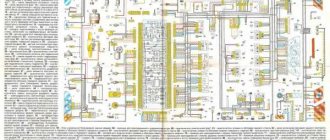
The diagram shows fuses in blue that need to be checked if problems arise with the devices on the VAZ 2110.
Instrument cluster circuit fuses
To check the temperature or fuel level gauge you must:
- Connect the ignition.
- Connect the positive power output of the device (attached to pin 5 in the white plug) to ground with a wire. If the arrow deviates, you need to check the condition of the wiring connecting the sensor and indicator.
- If the temperature indicator constantly indicates overheating, it must be disconnected from the sensor. If the needle drops to zero, the sensor needs to be replaced. Otherwise, there is a short circuit in the wiring to ground or failure of the indicator device itself.
- To test the device, you need to remove the white plug from the panel and apply power to pin 10 directly from the positive terminal of the battery. At the same time, a negative voltage is applied to pin 1. A working indicator shows a value equal to zero; if the arrow deviates, the device requires replacement.
Other possible repair options:
- Testing the tachometer is only possible on a stand that simulates engine operation. The speedometer is also checked using special equipment, which compares the measurement results with a reference device.
- After this, a visual inspection of the tracks on the printed circuit board located inside the combination is carried out. If cracks, ruptures and delaminations are detected, contact must be restored with solder. If repairs do not help, the instrument cluster will need to be replaced.
A video from the channel “In Sandro’s Garage” demonstrates how to replace backlight bulbs.
Precautionary measures
When repairing the instrument cluster, a number of recommendations must be followed:
- fuses are replaced with the ignition off;
- when testing devices, be careful to avoid short circuits;
- soldering is done with a low-power soldering iron with a thin tip;
- Removal and installation of the combination is carried out with little force so as not to damage the attachment points.
FakeHeader
Comments 118
What could it be, I connected it according to the diagram, without a temperature and fuel consumption sensor, and the starter stopped turning? before this, after not touching the wires everything was fine
It’s strange, of course, because the shield in this case is not connected at all with starting the starter. The new ones have immo, there is only an indication. Does the shield itself work “adequately”?
So I think it's strange. The native immo works. The shield works, except for the gasoline needle, but I think that's the problem. Could there be something wrong with the wires not being connected? but also strange
By the way, have you checked the starter circuits directly? Starting with the lock, relay, etc. Does the circuit at least close when turning the key?
Yes, I looked. I changed the relays and visually the wires. Got it. It was necessary to connect together the cut wires of pin 9 of the white block. Oddly enough, the car started. Now it torments me why the tidy resets to zero every time...
It’s clear, it even became interesting - I need to look at the old car diagram to see where the 9th one goes. I usually don’t do this if I have to completely remove the connectors (pads). First, I connect what is necessary for the new option, then, according to the diagram, everything unnecessary (unused) is removed from the harness, and then the remaining but still used wires are connected) Most often, looped masses and power wires, lighting (from the dimensions), and less often signal wires remain. Is it reset, in the sense that all the icons light up, the so-called test mode? Or LCD screen readings?
Everyone does it in their own way, but they still come to the truth. The icons light up when the ignition is turned on, the readings on the screen are updated every time, right? And I noticed that the arrows can hang in one place, and then when I turn the key again, they return. It seems like I’m looking at the diagram, and I didn’t connect pin 20 of the new one correctly, to pin 13 of the red one, but it should have been to pin 4 of the white one...
That's why I asked what exactly was happening. I just wanted to know what happened with the food. Very often they confuse plug-in 12V and constant 12V, which also came to light after the conversation. 20 contact terminal 30 (permanent) 21 contact terminal 15 (after ignition)
Now I have changed it. Everything has become normal. Does not reset. All that remains is to set the arrows
This is good! Set to zero position? The movement of the hands can be checked by turning on the test mode of the shield, it is more convenient.
When I set them to 0, I connected them, and they fell. Then I took it apart again, turned it against the direction of travel, everything works) I’m happy

