Refinement of the small circle of crankcase ventilation on the 8-valve
Not long ago I came across an interesting article on a website.
The essence of which is to change the path of crankcase gases through low crankcase ventilation. AvtoVAZ has always allowed a small ventilation of crankcase gases into the throttle assembly, both on 8 and 16-valve engines. But, with the release of the Lada Grant and the advent of the 126th engine, the circle of low ventilation has changed, now it does not enter the throttle, but directly into the receiver. And this is more correct.
After all, by increasing the amount of air behind the throttle valve, you can reduce jerks in transient modes. Roughly speaking, make the engine more elastic.
The advantages of this modernization should be the following: • Increases traction at low speeds; • The engine jerk disappears when the throttle is closed abruptly; • Cleaner throttle assembly; • Decrease in crankcase pressure;
So, without hesitation, I decided to do this on my 8-valve engine. The materials that I read said that there would be no special effect on an 8-valve engine; it would only be noticeable on 16-valve engines.
But even on the 8-valve engine in Grant the ventilation is made directly into the receiver, which means it’s better. It’s not for nothing that AvtoVAZ came to this decision years later.
This is what the ventilation picture looks like initially
We remove the low ventilation hose; it will no longer be needed. I wanted to take clamps from it, but they don’t tighten very well
To ventilate the receiver, you will need a hose of the same diameter, only twice as long. I still have a hose for HBO in my bins (from the ramp to the injectors). It fit perfectly
I plugged the hole in the throttle assembly using a small piece of hose and a bolt. For greater reliability, I tied the ends together with plastic ties.
The receiver has two rubber plugs that are pulled together with a little effort. I had a vacuum connected to one hole from the HBO reducer, and the second was free. It was in the second hole that I connected the small crankcase ventilation circle. The hose fit freely, so I tightened it with a clamp
Now the small ventilation circle looks like this:
The new hose does not interfere with anything. When the decorative engine cover is installed, the changes are not noticeable at all.
Now about impressions. On my first test ride, I didn’t feel much of a change in traction at low revs, but there was some effect. I would say that traction improved by 5%, no more. Or maybe this is just my own self-hypnosis. But I don’t have a 16-valve one, where it should be really noticeable.
But the nods when releasing the gas almost disappeared. Everyone is familiar with the situation when you are driving in 1st or 2nd gear at a speed of over 3 thousand and sharply release the gas pedal without squeezing the clutch, the car “nods” and a noticeable nod appears.
So, now these “nods” are barely noticeable. They remain, there is no longer the feeling that someone suddenly pressed the brake.
In general, I consider the revision extremely useful and can recommend it. Simple manipulations that will take no more than 10 minutes and will increase driving comfort.
What is a PCV valve
Theoretically, without this valve, the forced ventilation system cannot work correctly a priori. After all, it is the PCV valve that doses the supply of crankcase gases to the most important area - the space behind the throttle valve, right in front of the combustion chamber.
The PCV valve is not a check valve at all, as many people think. Yes, it is not blown in the opposite direction, but it also does not simply have two positions, open and closed. Everything is much more complicated. Inside the PCV valve there is a plunger loaded with a spring, the force of which is calculated depending on the engine volume, or more precisely, on the vacuum created in the manifold.
PCV Valve Design
The valve has four operating positions:
- The engine is switched off. The valve is completely closed, gases do not enter the manifold, and now they have nothing to do there.
- The engine is running at idle speed. In this mode, the vacuum in the manifold is the highest, the valve is completely open (100%) to ensure the supply of gases (essentially air) into the throttle space. Moreover, the amount of gases is strictly regulated and clearly controlled by the ECU, and the ECU already controls the idle speed controller depending on the amount of air supplied and a number of other factors.
- The engine operates in normal mode at medium speed and medium load. The PCV valve is approximately 50% open. The flow of crankcase gases is average, they burn efficiently in the cylinders.
- Maximum load and high speed mode. The PCV valve is open by 20-25%, the maximum amount of crankcase gases is burned, thereby the pressure in the crankcase is not dangerous for oil seals and gaskets, since it is completely controlled due to the vacuum in the manifold.
Algorithm of operation of the crankcase ventilation valve
On the Lada Vesta, the ventilation system is designed in such a way that in fact it always works the way a normal system works in the fourth mode. The flow of gases is limited only by a 1.7 mm jet built into the throttle pipe. In theory, the expectation was that the system would operate as a dual-circuit system.
This is how the ventilation scheme is implemented on 8 and 16-valve VAZ engines
The first circuit operates in the speed zone from idle to 1500 rpm. The pipe behind the throttle and the same 1.7 mm jet are involved here. The second circuit is connected to the ventilation already at high speeds, and gases begin to flow into the intake manifold up to the throttle through a hose with a diameter of 18 mm.
Design and principle of operation
As was said at the very beginning, the ventilation system removes crankcase gases from the VAZ 2114 back into the engine, preventing unburned fuel oil mixture from entering the atmosphere. It includes a pair of pipes through which gases are removed, and a filter that traps solid particles and clots.
The whole system functions as follows:
- the fuel mixture entering the engine burns and forms exhaust gases, most of which are discharged from the engine into the exhaust line;
- a small part of the gases leaks through the piston rings and enters the lower pipe of the ventilation system;
- From the lower pipe, gases enter the filter (made in the form of a multilayer mesh), after which, already purified, they return to the engine, where they burn out.
How often should cleaning be performed?
If the ventilation system is clogged and its filter is unable to clean the mixture passing through it, then not only unburned gases, but also oil particles and other pollutants will enter the engine. All this will ultimately have a negative impact on both the operation of the engine and its remaining service life.
The frequency with which the crankcase ventilation of the VAZ 2114 should be cleaned directly depends on the condition of the engine. So, if the car just recently came off the assembly line, and its engine has not clocked up 50,000 km, you shouldn’t even think about cleaning it, since the piston rings are still new, and there is practically no leakage of gases through them.
The first cleaning (as recommended by AvtoVAZ itself) should be performed after the car has covered 60,000 km. And all subsequent cleanings should also be performed after every 60,000 km.
Many owners of domestic cars with extensive experience say that 60,000 km is too much, and cleaning should be done at least every 30,000 km - this will help avoid many problems with the engine and extend its life. In this case, the first cleaning should be carried out after the first 60,000 km.
How to clean
To begin work, you will need to prepare the necessary tools, namely:
The crankcase ventilation of a VAZ 2114 is cleaned as follows:
- Loosen the fastening clamps of both pipes and then remove them.
- Inspect the pipes for cracks or chips - if the latter are present, replace the pipes with new ones of the same diameter.
- If the pipes are in good condition, clean them outside and inside with a damp cloth.
- Disconnect the throttle cable from the sector.
- Remove the pair of mounting bolts securing the throttle body to the receiver.
- Remove the bracket along with the cable.
- Unscrew the two bolts securing the cylinder head, and then remove the washers and rubber bushings located on them.
- Remove the cylinder head cover itself.
- Find the oil separator on the cylinder head cover and unscrew the mounting bolts that hold it.
- Remove the housing cover, and then remove the oil separator itself.
- Thoroughly rinse the filter mesh (oil separator) in gasoline (it is recommended to use highly purified gasoline for this) or kerosene.
- Clean the cylinder head cover from oil and adhering dirt (this is best done using a rag soaked in kerosene).
- Install the oil separator filter back into the cylinder head cover.
- Reassemble in exactly the same order, but in reverse order.
To avoid possible injuries, all work on dismantling the cylinder head cover and cleaning the ventilation system should be carried out only with the engine completely cooled.
It should be noted that when performing operations to clean the ventilation system, it is worth paying attention to the condition of the rubber bushings that fasten the cylinder head, as well as the gasket. If they are worn out or covered with cracks, they should be replaced immediately, without waiting for serious damage.
At the end of today's conversation, it is worth mentioning a situation where cleaning the crankcase ventilation system does not actually help improve engine performance. This happens when the engine is very worn out, and the secondary vapors entering it to burn out actually “choke” all its work.
There can be two ways out of this situation - either carry out a major overhaul of the power unit or remove the ventilation system to the external environment (in this case, unburned gases will not enter the engine, but into the atmosphere). True, at the same time, the environmental friendliness of the car will noticeably decrease, and it will no longer meet the high Euro standards. For this reason, such a decision should be postponed until the last resort.
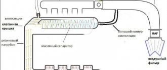
Diagram of the standard crankcase ventilation system
The crankcase ventilation system of VAZ engines consists of two circuits that operate at different load modes and speeds:
- The small ventilation circuit is connected to the valve cover and the intake manifold (behind the throttle body). This connection diagram provides intensive crankcase ventilation due to the vacuum that occurs in the intake manifold when the throttle is closed. To avoid an effect such as hyperventilation, the cross-section of the small circuit is limited by a jet in the cable throttle body with a diameter of 1.7 millimeters. This circuit operates in the region of 800-1500 rpm.
- A large ventilation circuit is connected to the valve cover and the air pipe (in the pre-throttle space). This scheme provides intensive crankcase ventilation at high speeds. The cross section of the large contour is 16-18 millimeters
Examples demonstrating the shortcomings of the standard crankcase ventilation system:
- A car is going down a hill with the gear in gear. In this mode, the engine operates at higher speeds with a reduced load. A high vacuum is created in the crankcase, and a large ventilation circuit is connected, in which there are no control valves. Since both circuits are connected to one volume of the oil trap, a strong vacuum in the crankcase will draw a fresh portion of air bypassing the throttle. The mass air flow sensor will show increased air flow, and the ECU will try to close the throttle. Having realized that this is not possible (it is already closed), the lean mixture will be corrected by increasing the fuel supply (fuel consumption will increase). As a result, the entire internal volume of the engine will work as a parallel receiver of very significant volume, connected to the intake, bypassing the throttle. It is this volume that will interfere with the formation of a high-quality mixture.
- A car in a traffic jam drives under tension with additional consumers (for example, the air conditioner is on). The compressor clutch is connected, the load increases abruptly. The engine does not have enough air, it begins to pull it from the crankcase, bypassing the throttle. But the ECU is also aware of the clutch engagement and also supplies more air by opening the throttle. The vacuum drops sharply, the vacuum brake booster (VBR) does not have enough strength to hold the car. Leap forward. The ECU sees an increase in oxygen and closes the throttle. A sharp increase in vacuum, VUT seizes. The car jerks, the transmission hits. And so on ad infinitum.
As a result, in both cases, when the engine is running, speed jumps occur and the engine choke under the load. Jerking and vibration are possible on manual transmissions, automatic transmissions and automatic transmissions. To eliminate these shortcomings, it is proposed to modify the design according to one of the presented schemes.
Why is cleaning necessary and its frequency?
When the ventilation system is clogged, an emulsion containing soot and oil residues settles inside the engine, resulting in the creation of excess pressure, leading to damage to the seals. This leads to loss of sealing and oil leaks, which can be seen during an external inspection of the engine block. Crankcase gases are gases from engine cylinders that are not discharged through the exhaust valve, but are squeezed out into the crankcase through the gaps of the pistons and piston rings when the engine is running. This process occurs especially intensively in worn-out engines with high mileage. For VAZ 2101-2107, these are mileages of 80-100 thousand km.
If the crankcase ventilation is not cleaned in a timely manner, the operation of the fuel supply system will be affected. In carburetor engines, the air filter and the carburetor itself become dirty; in injection engines, the throttle assembly, inlet pipe and sensors become dirty. All this leads to a decrease in power, problems with operation, and in some cases a complete stop of the engine. To avoid this, additional elements are introduced into the ventilation system to clean crankcase gases from emulsions containing oil.
If the crankcase ventilation system is not cleaned in a timely manner, the hoses crack due to excess pressure. This causes excess air to be sucked into the engine. Carburetor engines are not so sensitive to this problem, but in injection systems the quality of the mixture sharply deteriorates, the stability of the engine is disrupted and its power is reduced.
The best option is to clean the crankcase ventilation on a VAZ classic immediately before changing the oil. This frequency allows you to keep the system in order, change cracked hoses on time, extend the life of the engine, and reduce fuel consumption without loss of power.
Video: How to disassemble and clean the breather, crankcase ventilation
Schemes for upgrading the crankcase ventilation system
Schemes for modifying the crankcase ventilation system, as well as a description, are provided by IgorRV.
For LADA cars with manual transmission and AMT (“robot”), scheme No. 1 “Crankcase ventilation scheme with PCV valve for E-GAS and cable throttle” is suitable:
It is necessary to install a PCV valve (article 94580183, price about 400 rubles) from a foreign car into the small crankcase ventilation circuit. When connecting the PCV valve to a small circuit on an E-GAS, use a new hose (petrol-oil-resistant 8 mm without fabric reinforcement). On a cable choke, connect to the receiver, not to the choke.
As a result, the valve will shut off the circuits in transient modes, which will allow:
- Accept the load without jerking or dropping engine speed (for example, when the compressor is running, heated windows, seats, etc.).
- Reduce vibration load at idle
- Increase traction from the bottom (noted by owners of automatic transmission with VAZ-21126 engine, manual transmission with VAZ-21227, 21126 and 11186 and AMT with VAZ-21127).
- Get a sharper response to the gas pedal and faster shifts (on AMT). Perhaps due to the fact that the valve does not allow the engine to slow down, maintaining a more optimal switching algorithm.
- Reduce oil consumption through ventilation.
The valve replacement period is 40,000 km.
Modification of the crankcase ventilation system Kalina 8 valves
This system could be improved a little. One of the 3 pipes supplies crankcase gases directly to the throttle valve assembly next to the IAC. If they contain oil, it will definitely settle there. This is how the IAC becomes clogged. So, to avoid this, you can embed a regular fuel filter right in the middle of this pipe.
It will trap oil particles contained in crankcase gases. After a few hundred kilometers, you will see for yourself. Monitor the condition of this filter and promptly change it to a new one. On average, as practice shows, it needs to be changed every 1000 kilometers.
Cleaning the crankcase ventilation system on VAZ 2113, VAZ 2114, VAZ 2115
Welcome! Crankcase ventilation system - it is present in many gasoline cars, due to it the environment is not heavily polluted and all exhaust gases are sent back to the car engine for combustion; in old cars, people themselves modify this system in such a way that all the crankcase ventilation hoses go outside (And this is all due to the fact that the engine begins to release contaminated crankcase gases and if they fly back into the engine, they will simply choke it), because of this, the environment suffers, we immediately warn you, but the engine’s power increases and it It will be much easier to breathe.
Note! To clean the crankcase gas system, you will need: Screwdrivers, all kinds of wrenches and pliers!
Summary:
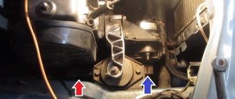
Where is the crankcase ventilation system located? This system consists of two hoses (Indicated by arrows) and a filter that passes all dirty air and oil particles through and thereby cleanses all the air of this rubbish, the filter itself is located in the valve cover (Location is indicated by a green arrow), in more detail if If you want to see it, look at the small photo, it is made in the form of a grid pack.
Note! The principle of operation of the ventilation system is this: when the engine is running, the mixture burns and for the most part everything goes into the exhaust pipe, but still, a little bit through the piston rings, vapors break through and in this case the ventilation comes into operation, due to it these vapors come out first along the lower ventilation pipe (Indicated by a blue arrow in the photo above), then they are cleaned by a filter and pass in purified form to the upper hose, the hose of the small ventilation branch (Indicated by a red arrow), and thus these unburnt vapors fly back into the car engine, to re-combustion, that’s how the ventilation system works!
When should you clean the crankcase ventilation system? When the filter becomes clogged with dirt, when the hoses become clogged, all this dirt begins to fly into the engine, so that the dirt does not fly, you need to periodically wash the filter and clean the hoses inside with a cloth, the frequency of this depends on how worn out the engine is, in new engines the first 50 thousand in general There’s no point in even getting into the crankcase ventilation system, because the rings on the pistons are intact and there’s not a lot of vapor breaking through them into the system. On used engines, we recommend it more often, since this operation is not long and there is no harm from it, only benefit ( The factory calls the figure 60,000 thousand kilometers, this is a lot, if you treat your car well, then clean the system much more often, once every 30,000 thousand kilometers approximately).
Engine crankcase ventilation system 2111 (diagram)
The engine crankcase ventilation system 2111 of VAZ 2108, 2109, 21099 cars with fuel injection is designed to effectively remove gases from its crankcase and burn them in the combustion chambers. As a result, the emission of harmful substances into the atmosphere is reduced.
Design of the crankcase ventilation system for engine 2111 (diagram)
Engine crankcase ventilation system 2111 for VAZ 21083, 21093, 21099 (injector)
1. Engine crankcase.
2. Breather.
3. Hose from the breather to the valve cover pipe.
4. Oil separator under the valve cover.
5. A thin hose from the valve cover to the fitting with the throttle body nozzle.
6. Fitting with a jet on the throttle valve block.
7. Thick hose from the valve cover to the inlet pipe.
Operating procedure for the 2111 engine ventilation system
— At idle, with the throttle valve closed, crankcase gases under high vacuum are sucked through the breather and its hose under the valve cover to the oil separator. Further, under the influence of the same vacuum, through a thin hose from the valve cover to the fitting with the nozzle into the throttle assembly, under the throttle valve and further into the combustion chambers (small branch). The jet limits the amount of crankcase gases entering at idle, as normal operation in this mode may be disrupted.
— In operating and power modes, when the throttle valve is slightly open and more efficient crankcase ventilation is required, crankcase gases also flow through the breather, its hose, to the oil separator under the engine valve cover. And then they are sucked through a thick hose from the valve cover into the intake pipe to the throttle body (large branch). Crankcase gases practically do not flow through a thin hose, since when the throttle valve is open, the vacuum behind it drops significantly.
Engine crankcase ventilation system malfunctions 2111
— The main and most common malfunction of the ventilation system is clogging. A clogged crankcase ventilation system can lead to negative consequences in the operation of the car engine. The hoses or oil separator or jet in the throttle assembly may become clogged.
The consequences may be the following:
— violation of the normal operation of the engine at idle (increasing the idle speed control steps more than normal - the speed increases);
— engine oil leaking from under the engine seals (as excess pressure is created in the crankcase);
— oil contamination of the engine air filter and, accordingly, a drop in power plus an increase in fuel appetite;
— contamination of the engine itself with tar deposits.
Notes and additions
— How to clean the crankcase ventilation system, see “Cleaning the crankcase ventilation system of a car engine.”
Twokarburators VK - More information on the topic in our VKontakte group, on Facebook Twokarburators FS and on Odnoklassniki - Twokarburators OK
More articles on the 2111 engine
— Features of measuring compression in the cylinders of an injection engine
— Diagram of the engine control system 2111 (Euro-2)
— Comparison of engine parameters 2111 and 21083
How to clean the crankcase ventilation system on a VAZ 2113-VAZ 2115?
1. First, remove the hoses, which ones specifically relate to the crankcase ventilation, we already said at the beginning of the article, so you will need to remove them and wash them inside and wipe them with a cloth (The hoses are easy to remove, they are secured with clamps), if the hoses are all cracked, we recommend them replace with new ones.
2. Now disconnect the tip of the throttle cable from the throttle assembly sector, you will find more details on how to do this in the article entitled: “Replacing the throttle cable”, there will be point 1 and there are 4 photos in it, you need exactly 2 and 3 and Read the description for them.
Next unscrew the two nuts that secure the cylinder head cover (see photo 2), remove the metal washers and rubber bushings underneath them (see photo 3) and finally, remove the cover itself from the cylinder head.
Note! Check the removed rubber bushings and, if necessary, replace them with new ones if they are torn or lose their elasticity; in addition, under the block head cover that you have removed, there will be a rubber gasket; in any case, it must be replaced with a new one, even if the old one is still in your opinion I think it's in good condition!
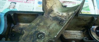
4. As soon as the cover is removed, turn it over and inside it you will find two bolts that secure the oil separator body, these bolts will need to be unscrewed (see photo 1) and the body removed (see photo 2), then remove the oil separator itself (We previously it was simply called a filter) and rinse all its meshes thoroughly with gasoline, and also rinse the cylinder head cover from dirt adhering to it, well, that’s all, you can put the oil separator back in its place, but only when installing, orient it as this is shown in photos 3 and 4 below.
Crankcase ventilation hose VAZ 2114
Hi all. My mileage is already 73,000 km, and according to the maintenance book, the crankcase ventilation system needs to be flushed every 60,000 km. This is all due to the fact that tarry deposits from crankcase gases accumulate in the system, making it difficult to remove these gases into the engine cylinders for combustion. Because of this, the pressure inside the engine increases and oil leaks appear through the seals, so it is necessary to flush the system. So I chose the time and bought what I needed for washing.
Namely, I decided to install a new gasket for 35 rubles, and put it on a sealant for 110 rubles, because oil was constantly oozing from under the old one, I also bought kerosene for 35 rubles. for washing, you can use gasoline, and a brush 20 rubles.
For the work you will need a 10 mm wrench, a Phillips screwdriver and about an hour of time. First of all, remove the decorative casing.
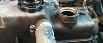
Unscrew the oil filler plug and pull it towards you.
Then remove the hose of the large branch of the crankcase ventilation system by loosening the two clamps.
If you follow my blog, you know that I recently changed the oil dipstick. Everything would be fine, but after a short trip, looking under the hood, I discovered that the dipstick was not seated tightly, as if it had been squeezed out of the mounting hole.
Having pulled out the dipstick with the car running, I felt that there was a decent amount of air blowing from there. In principle, as far as I know, it should blow in any case, but there is a limit to everything. Upon closer inspection, the dipstick also turned out to be of poor quality (crooked, rubber too soft). I bought another dipstick in the store (it has stronger rubber and harder metal), it fit tightly and was no longer squeezed out. By the way, the new probe turned out to be a little shorter than the standard and low-quality probe, this one made by AVTOVAZ (so they said in a large store and the marking was appropriate).
Despite the fact that the new dipstick fit tightly, I decided for myself that it was time to clean the crankcase ventilation system and change the corresponding hoses.
So, I bought three hoses produced by BRT (BalakovoRezinaTekhnika): 1. A large thick one that goes directly from the crankcase to the valve cover; 2. A thinner hose that goes from the corrugation of the air filter housing to the valve cover (during disassembly it turned out that the old one was torn and there was air leakage through it); 3. The thinnest hose that goes from the valve cover to the throttle body. In addition, the original clamps, which, like the hoses, were 10 years old, were replaced with Norma clamps.
I bought oil separator screens (whose production I didn’t catch, and it doesn’t matter). I didn't want to clean the old ones.
Due to the fact that replacing the oil separator screens involves removing the valve cover, we purchased fungi (two rubber bushings for the valve cover nuts BRT) and a valve cover gasket (VCT).
The whole event went off without incident. Approximate order: 1. remove three crankcase ventilation hoses (which ones were described above); 2. remove the throttle cable bracket (two bolts), turn it towards the air filter; 3. Unscrew the valve cover nuts and remove the valve cover.
Similar articles
The principle of operation of the crankcase ventilation valve of internal combustion engines
The crankcase ventilation system (CVV) is simple and its operating principles are very simple. The internal space of the engine is connected to the intake manifold by a hose, and under the influence of vacuum, the carbon dioxide accumulated in the engine is taken from the inside into the intake tract, then enters the cylinders. The crankcase ventilation valve (CVVV) has a unipolar direction; it allows gases to move only in one direction (from the crankcase to the intake manifold), without letting them back.
SVKG is essentially the same breather that is found in the gearbox and automobile axles. But if in the transmission the valve opens, releasing the accumulated carbon dioxide into the surrounding atmosphere, then in the engine, under the influence of vacuum, they are removed faster and more efficiently in the internal combustion engine itself. An example can be given - on ZMZ-24 engines, open-type ventilation was previously used, and through the outlet pipe in the cover of the pushers the KGs came out (indicated by an arrow in the figure below).
Since 1977, forced closed-type SVKG began to be used - through a hose coming from the valve cover of the internal combustion engine, gases began to be diverted under the carburetor. Due to forced SVKG:
- the emission of harmful substances into the atmosphere is reduced;
- The pressure inside the crankcase is reduced more effectively, so oil seals and gaskets are not squeezed out;
- the engine does not “suffocate”, it works with normal output.
In the classic SVKG scheme, there are two gas outlets from the engine into the intake tract:
- one of them is direct-flow;
- the other is of the forced type.
Also, as an example, we can consider the ZMZ-402 engine system; in the figure below you can see that from the valve cover, gases flow through a thick pipe directly into the carburetor, and through the lower pipe into the intake manifold itself, bypassing the device that creates the necessary proportion of air with fuel.