We examined VAZ 2113 2114 2115 cars, also called Lada Samara. Cars were produced with 8 and 16 valve gasoline engines in 2000, 2001, 2002, 2003, 2004, 2005, 2006, 2007, 2008, 2009, 2010, 2011, 2012 and 2013. During this time, some models were updated. In this publication we will show a description of VAZ 2115 2114 2113 fuses with block diagrams and their locations.
Fuses and relays VAZ 2114, 2115, 2113
Today, every car, regardless of type, is equipped with special protection for all electrical systems.
This protection is called a fuse. They are installed so that in the event of a short circuit or malfunction, the system can turn off via a fuse, thereby protecting itself from breakdown. Fuses are used for every electrical circuit, from a small light bulb to an engine's ignition system. More important engine systems are equipped with special relays, they protect various pumps, electric motors and other powerful sources of electricity consumption. The fuse is a small structure consisting of a plastic casing with a fusible element inside. If a short circuit occurs, the thin contact melts under the influence of current, which interrupts the electric current. The simplest electrical fuse is a thin copper wire inserted into a circuit. If the upper limit of the supplied current increases, the contact begins to melt and interrupts the flow of electricity. Here there is a description of all fuses and relays for VAZ 2113, 2114, 2115 models of injection and carburetor types, old and new models.
Recommendations for care and maintenance
- Buy original fuses. Domestic or foreign, it doesn’t matter;
- Install strictly in accordance with amperage ratings. Unacceptable with lower or higher current strength. In the first case, this will lead to damage to the module, in the second - to breakdown of the unit, which is attached to the fuse;
- Carefully check the quality of fixation of terminals and limit switches on the board. If loose, tighten and press with pliers. A spark can cause a fire and melting occurs;
- If moisture gets in or condensation forms inside the mounting block, remove the cover, dry it, and if necessary, blow it with a stream of compressed air.
Carry out preventive and diagnostic work in the fuse box with the battery terminals removed in order to prevent a short circuit in the circuit.
The average service life of fuses is 40 – 60 thousand km. The service life of foreign analogues is 10–15% longer. Before replacing, read the instructions and get advice from service station specialists.
Interpretation of fuses and relays of injection models
The main electrical fuse module 2114-3722010-60 is located under the front engine compartment. This arrangement allows for quick access to all electrical systems of the car.
Block location
Please note that the location of the electrical fuse module may depend on the type of equipment and year of manufacture of the vehicle. As a rule, this is the upper right part of the engine compartment, under the front windshield. The mounting block is made of plastic in the form of a rectangular box. To protect against accidental opening, the box is equipped with special latches. To open the module, you need to snap off the two protective brackets and lift the top plastic protection. Under the cover are all the main control relays and electrical fuses of the vehicle.
To quickly remove the fuse, special plastic pliers are located on the plastic protection cover. With their help, you can very easily get any element. You need to grab the top edge of the plastic case with pliers and carefully lift the element.
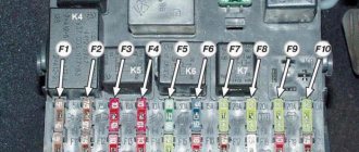
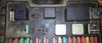
For the convenience of the user, on the top plastic cover there is a complete diagram, made in the form of a schematic image, which shows all the electrical fuses and relays indicating the current strength (A).
Fuse and relay diagram for injection models
Table 1. Explanation of fuses and relays 2114-3722010-60
| № | Current, A | Explanation of fuses |
| F1 | 10 | Rear fog lights, rear fog light indicator lamp |
| F2 | 10 | Turn signals and turn signal breaker relay. Alarm system. Hazard warning lamp |
| F3 | 7,5 | Interior and luggage compartment lighting systems (interior lamp, luggage compartment lamp, ignition key illumination). Brake brake lamp, on-board computer backlight lamp. Engine control lamp |
| F4 | 20 | Rear window heating control. Portable lamp connection socket |
| F5 | 20 | Relay for monitoring and turning on the sound signal. Cooling system engine switch fuse and relay |
| F6 | 30 | Control and relay switching on electric windows |
| F7 | 30 | Electric motor control - heating system, interior heater, windshield washers, headlight cleaners. Interior cigarette lighter, glove box lamp. Turn on the heated rear window. |
| F8 | 7,5 | Turning on the right fog lamp |
| F9 | 7,5 | Turning on the left fog light |
| F10 | 7,5 | Side light for the left side body, indicator light for turning on the side lights (on the display), lamps for illuminating the license plate and engine compartment, illumination lamp for switches, cigarette lighter, heater control levers. Instrument lighting switch. |
| F11 | 7,5 | Right side body marker light |
| F12 | 7,5 | Front right low beam headlight |
| F13 | 7,5 | Front left low beam headlight |
| F14 | 7,5 | Front left high beam headlight. Light indicator lamp. |
| F15 | 7,5 | Front right high beam lamp. |
| F16 | 15 | Body turn signals, relay-breaker for turn signals and hazard warning lights. Control relay and reverse lamps, indicator lamps for the on-board instrument control system, lamps for oil pressure, handbrake activation, brake fluid level, battery charge. On-board computer, engine generator winding. |
| F17-F20 | Spares | |
| № | Relay circuit | |
| K1 | Headlight cleaners | |
| K2 | Turn signals and hazard warning lights | |
| K3 | Windshield wiper | |
| K4 | Monitoring the serviceability of brake light lamps and side lamps | |
| K5 | Window lifters | |
| K6 | Sound signal | |
| K7 | Heated rear window | |
| K8 | High beam headlights | |
| K9 | Low beam headlights | |
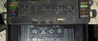
Decoding fuses and relays of block 2114-3722010-18
VAZ-2114, 2115, 2113 cars of the first models with a carburetor have certain differences in the fuse module.
Old style block fuse and relay diagram
Table 2. Decoding of fuses and relays of block 2114-3722010-18
| № | Current, A | Explanation of fuses |
| F9 | 7,5 | Right rear fog lamp |
| F8 | 7,5 | Left rear fog lamp |
| F1 | 10 | Front headlight cleaners at the moment of switching on, wiper contacts, headlight washer switch valve, headlight wiper switch relay contacts |
| F7 | 30 | Front headlight wipers during operation, winding of the relay for turning on the wipers, fuse for the interior heater, windshield washer, gearbox and timing controller for the rear window wiper, valves for turning on the front and rear washer, relay (winding) for turning on the engine cooling system, relay for turning on the rear window heating, glove box lighting, rear window heating control lamp |
| F16 | 15 | Turn signal indicators and activation of hazard warning lights in turn mode, indicator control lamp, reversing lights, gearbox and relay for activation of windshield washers, generator winding (at startup), control lamps for brake fluid, oil pressure, carburetor flap, hand brake. "STOP" display lamp, voltmeter and coolant temperature indicator |
| F3 | 10 | Interior lighting and rear brake light |
| F6 | 30 | Power windows, power windows on/off relay |
| F10 | 7,5 | License plate lights, engine compartment lamp, warning light on the dashboard (exterior lighting), instrument panel lights, cigarette lighter light, heating lever lights |
| F5 | 20 | Relay for turning on the cooling system fan (electric motor), sound signal. |
| F10 | 7,5 | Left front marker light Left rear marker light |
| F11 | 7,5 | Right front headlight, right rear headlight |
| F2 | 10 | Hazard warning lamp, turn signals and hazard warning relay. |
| F4 | 20 | Rear heated glass, heating on, portable socket, cigarette lighter in the cabin |
| F15 | 7,5 | Front right high beam |
| F14 | 7,5 | Front left high beam Light switch |
| F13 | 7,5 | Left low beam |
| F12 | 7,5 | Right low beam |
| № | Relay circuit | |
| K1 | Headlight washers | |
| K2 | Hazard and turn signals | |
| K3 | Windshield wipers | |
| K4 | Monitoring the health of lamps | |
| K5 | Windows | |
| K6 | Sound signal | |
| K7 | Heated rear window | |
| K8 | High beam headlights | |
| K9 | Low beam headlights | |
About problems with heated seats
Like all electrical circuits, heating devices have a fuse, and this model has two. One is installed in the mounting block, this is F16
, and the second is suspended under the instrument panel. If the control lights do not light up when you press the heating button, the problem must be looked for in the fuses.
The heating elements are directly switched on by an electromagnetic relay, which is also located under the instrument panel. After it operates, you should use a voltmeter to check the presence of voltage at terminal number 87. If it does not operate, check the relay winding with an ohmmeter, these are terminals numbered 86 and 86, or by installing a new one.
Next, check the presence of power, with the switch on, at the connectors under the chairs; to do this, they are disconnected from the heater wires. The black wire is connected to the ground of the car, and the second wire should have 12 Volts of the on-board network. At the same time, use an ohmmeter to check the resistance of the heating element windings. Most often the problems are located there. Windings and supply wires break or burn.
In some cases, they can be restored, but to do this you will have to remove and disassemble the seat cushions. Of course, these are not all possible reasons why heated seats do not work on the VAZ 2114 and 2115. The article gives directions for finding possible problems in the heating systems, and then you will need the experience and skill of the driver with the electrical equipment of the car.
Starter, ignition, rear fog lamp relay
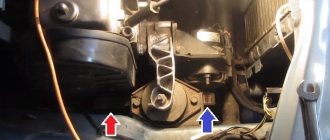
In order to carry out quick checks and repairs, the ignition system relay is installed under the front dashboard of the car, behind the hood release handle. It is located just below the central dashboard. The module is closed with a plastic plug, which must be opened slightly to test for functionality.
Starter, ignition, rear fog lamp relay
Next to the indicated relay, there is a similar one for the rear fog lights and the starter.
The main task of the relay when igniting is to reduce the applied load to the contacts. When the engine starts, the relay turns off some electrical circuits in the vehicle system. The system is used not only in injection, but also in carburetor engines.
In the event of a malfunction or malfunction in the ignition system, it is necessary to monitor the operation of the relay. For this purpose, open the box and carefully remove the desired element. It is attached using contacts to special grooves. The first thing to do is look at the oxidation of the contacts, if necessary, clean them with a soft cloth or treat them with a special liquid.
To check functionality, you need to use a regular multimeter. We connect to incoming connections and check the numbers. If there is no short circuit when current is applied, it means the element is not working. Replacement is carried out in a similar manner. It is necessary to use a standard element with the number of amperes indicated on the housing.
Why do you need heated seats?
This is an important and necessary thing in your car, especially at a time when it is bitterly cold outside. If you very often get into the cabin of a car that has been standing in the cold for a long time, it is not only unpleasant, but also dangerous to the health of the driver and passengers. But at the same time, overheating of the seats also promises problems for those sitting on them, and in some cases for the car.
You can find a lot of information about both the benefits of heating and its inappropriateness. Let's try to understand this information together. Long trips with the heaters on can have a negative impact on men and women. Therefore, you need to be able to use this function correctly and in a timely manner. Sitting in a cabin with leather seats in winter can cause problems for drivers of both sexes, in the form of cystitis or prostatitis.
There are certain, developed and time-tested rules for using heating:
- Do not allow the seats to become overheated;
- In a cold car interior, you should turn on the heating system, but do not sit on them for some time;
- After warming up, the system must be turned off, further heating must be carried out using a heater;
- There is no need to stay in the salon for a long time in warm clothes.
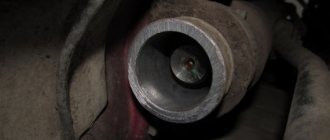
Front fog lamp relay
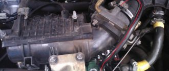
Front fog lights are not standard equipment on the model and are equipped depending on the configuration. The relay itself (if there are fog lights) is located in the engine compartment on the left mudguard.
Front fog lamp relay
Important! To access the relay, you must remove the battery! Without performing this manipulation, it will be difficult to remove and check its functionality.
Replacing a faulty element is very simple. You need to take a Phillips screwdriver (with a short handle), unscrew the bolt securing the relay to the car body, and check the element for malfunction. If it fails, we buy a new one and put everything in the reverse order.
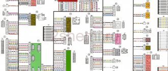
How to connect fog lights on a VAZ 2113-2115
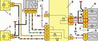
Scheme for switching on fog lights: 1 – fog lights; 2 – relay for turning on fog lights; 3 – mounting block; 4 – switch for fog lights with a control lamp (on the left) and a backlight lamp (on the right); 5 – external lighting switch (fragment); A - to power supplies; B - to the instrument lighting regulator
On cars in a variant version, fog lights can be installed in the front bumpers. The diagram for switching on the fog lights is shown in Fig. The headlights are turned on by switch 4 using auxiliary relay 2 type 113.3747-10 installed in the engine compartment on the left mudguard. The fog lights can only be turned on if the exterior lighting is switched on with switch 5.
There are several options for mounting headlights. First of all, I will say that only options for mounting in the bumper are being considered, otherwise there is no point in PTF. The most optimal are the domestically produced OSVAR or Avtosvet headlights, they shine well, are relatively inexpensive, some of them have plastic covers, and you can find spare glasses for them, which is essential for PTF.
The easiest way to mount it is on the plastic in the bumper. This is how they fasten in many car repair shops, but this method of fastening seems to me not reliable and not durable, because it still needs to be fastened to strong metal structures. Below we will outline how to install PTF.
There are two holes in the bumper for the standard mounting location for the PTF, for the standard L-shaped fasteners. The easiest way is to lie under the bumper and attach the PTF yourself to its regular place, you will see: both the markings in the plastic and the holes in the bumper beam (there are 4 of them, two for each headlight), relative to the bumper mounting bolts, they are located closer to the edges of the bumper. First you need to screw the PTF onto the standard holes, adjust the height and width, and then adjust the tilt. After installing the PTF in the bumper, proceed to pulling and connecting the wires as shown in the diagram.