Crankcase ventilation system Kalina 8kl
Today we’ll talk about the crankcase on Kalina with an 8-valve engine. And to be more precise, about cleaning this system. Crankcase gases straight from the crankcase (hence the name) are sent mixed with air to the intake manifold for re-burning, thus saving a certain percentage of fuel. So, along with the gases, oil particles enter the system and clog it.
It is this oil that needs to be cleaned from the crankcase ventilation system. Over time, plaque forms on the walls of the hoses, which impedes the passage of gases.
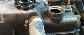
In the Kalinovsky engine, in the valve cover, there is a special separator that separates crankcase gases from the oil. It gets clogged the most. So, let's get started. The entire ventilation system consists of 3 pipes. We need to unscrew them.
Then remove the valve cover. There are two bolts on the back side, unscrew them and get to the separator.
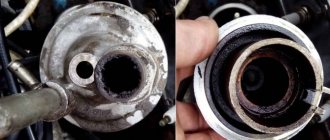
The easiest way to clean it from oil and deposits is in a bath of gasoline or solvent.
While the separator is acidifying, you can work on the pipes. In general, if they are heavily soiled, it is advisable to replace them with new ones. In my case, I replaced only one - coming from the valve cover to the air filter pipe. The rest were washed with carburetor cleaning fluid (great stuff, it corrodes absolutely everything). The separator itself can also be washed a second time with this thing.
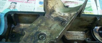
We wipe everything with a clean cloth and put it back together as it was. Pay attention to the condition of the valve cover gasket. It is considered disposable and it is better to replace it with a new one each time you remove it in order to avoid oil leaks.
contents .. 238 239 240 241 ..
Lada Kalina 2. Abundant crankcase gases: reasons
The main causes of gases from the engine crankcase:
- Malfunction of the crankcase ventilation system
-Breakthrough of gases into the crankcase
Signs of malfunction of the crankcase ventilation system and valve
The crankcase gas recirculation system has significantly reduced harmful emissions. At the same time, it is quite easy to operate and requires virtually no intervention when repairing the engine. However, like any system, it is also not ideal.
The fact is that a system malfunction is not as obvious as a breakdown of any other engine unit. But when the system fails, it can result in quite large financial losses for the car owner. The breakdown of such a system is not clearly pronounced; the car owner will already notice the immediate consequences of its failure. Signs of failure are usually:
— fogging of system hoses
- increased oil consumption
- valve cover gasket leaking
Presence of oil in the air filter pipes. Excessive gas pressure inside the engine. And the most critical case is the squeezing out of the crankshaft seals. Agree, a silent assistant can lead to big problems.
Gas breakthrough into the crankcase
The breakthrough of gases into the crankcase is associated with excessive oil consumption. Gases do not break into the crankcase, but into the engine valve cover through a torn or crumbled valve sleeve. This happens occasionally. The valve then loses alignment on the seat and does not fit well. Compression in the cylinder drops, the fuel does not burn out completely, but externally and audibly the engine is operating quite normally. Such a malfunction can really be fixed in two hours. You can verify the correctness of the diagnosis by measuring the compression in the cylinders, or, which is easier, with the valve covers removed, see where the gases are coming from. Due to excessive oil consumption, severe leakage through all seals, and smoke from the breather, it is too early to pronounce a “death sentence” on the engine. We need to look into it carefully, not wasting time.
How to check the crankcase ventilation valve
As with any vehicle component, it is necessary to periodically inspect and correct the malfunction. The fact is that the recirculation valve operates in a rather dirty environment. Mandatory, cleaning is necessary. At the slightest suspicion of its malfunction, you need to check its performance. If a valve with additional electronic systems is installed, the vehicle's self-diagnosis may show an error. In more simplified versions, diagnostic skill is required.
1. Connect the ventilation hose to the valve. 2. Start the engine and let it idle. 3. Touch the valve inlet with your finger and make sure there is vacuum. At this moment the valve stem will move. 4. If vacuum is not created in the valve inlet, clean or replace the valve.
How to determine malfunctions of the engine crankcase ventilation system
During operation, excess pressure and gases arise in the crankcase of an internal combustion engine. Crankcase gases contain vapors of fuel, water, oil, etc. Their effective removal is very important, because they can significantly deteriorate the quality and condition of motor lubrication, which usually leads to excessively rapid wear of power unit components. So, to remove these gases, it is customary to use a special crankcase ventilation system. It has already happened historically that today there are two systems: open and closed. Considering that crankcase gases are extremely toxic, it is impossible to vent them outside, so modern cars have used a closed ventilation system for such gases, in which the crankcase gases are burned into the combustion chamber. But due to the excessive pressure of the motor lubricant, oil particles also rise together with the gases, and they must not get into the combustion chamber; it is the separation of oil from gases that is the main task of the ventilation system. This is usually done using special oil traps. If we talk about oil traps, they can be very diverse, but at the same time they all have the same operating principle: to deposit all the heavy lubricant particles on the walls, and let gases through. This is done using labyrinths, vortices and grids. Immediately after separating the lubricant from the gases, the oil flows back into the engine, while the gases are sent to the manifold in small portions, and from there they enter the engine and are burned there. A special valve regulates the supply of gases to the manifold; it can open when there is excess pressure and close when there is a vacuum. On every car, the crankcase ventilation system needs periodic cleaning and inspection. If the system becomes severely clogged, the pressure in the crankcase rises, and as a result, oil may begin to pour out through the dipstick. Typically, this phenomenon indicates a valve malfunction or a clogged oil trap. If the reason is a malfunction of the oil trap, then motor lubricant begins to flow into the combustion chamber, as a result of which the vehicle begins to smoke, a rather unpleasant odor occurs, and when this problem is not corrected in a timely manner, this can lead to a stuck ring. Problems associated with the crankcase ventilation system of the power unit, as well as any other engine problems, are much easier to prevent than to then eliminate the consequences. If the very first cause of failure of the crankcase gas exhaust system occurs, and this is poor separation of lubricant from gases, or excess pressure, repairs must be carried out immediately. Identifying signs indicating a malfunction of the crankcase ventilation system is usually not difficult. If the oil trap is clogged or the valve is broken, then excess lubricant pressure can be detected using a simple check; for this, the neck of the lubricant filler hole is closed with the palm of your hand. If there is excess pressure in the system, then the palm will push away with a force that gradually increases. Well, if the oil catcher breaks down, small particles of engine lubricant get into the pipes on the intake manifold, sometimes they can even settle on the air filter, and, accordingly, the car’s exhaust gases change their color.
contents .. 238 239 240 241 ..
Modification of the crankcase ventilation system Kalina 8 valves
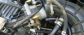
This system could be improved a little. One of the 3 pipes supplies crankcase gases directly to the throttle valve assembly next to the IAC. If they contain oil, it will definitely settle there. This is how the IAC becomes clogged. So, to avoid this, you can embed a regular fuel filter right in the middle of this pipe.
It will trap oil particles contained in crankcase gases. After a few hundred kilometers, you will see for yourself. Monitor the condition of this filter and promptly change it to a new one. On average, as practice shows, it needs to be changed every 1000 kilometers.
Crankcase ventilation system Kalina 8 valves
Today we’ll talk about the crankcase on Kalina with an 8-valve engine. And to be more precise, about cleaning this system. Crankcase gases straight from the crankcase (hence the name) are sent mixed with air to the intake manifold for re-burning, thus saving a certain percentage of fuel. So, along with the gases, oil particles enter the system and clog it.
It is this oil that needs to be cleaned from the crankcase ventilation system. Over time, plaque forms on the walls of the hoses, which impedes the passage of gases.
In the Kalinovsky engine, in the valve cover, there is a special separator that separates crankcase gases from the oil. It gets clogged the most. So, let's get started. The entire ventilation system consists of 3 pipes. We need to unscrew them.
Then remove the valve cover. There are two bolts on the back side, unscrew them and get to the separator.
The easiest way to clean it from oil and deposits is in a bath of gasoline or solvent.
While the separator is acidifying, you can work on the pipes. In general, if they are heavily soiled, it is advisable to replace them with new ones. In my case, I replaced only one - coming from the valve cover to the air filter pipe. The rest were washed with carburetor cleaning fluid (great stuff, it corrodes absolutely everything). The separator itself can also be washed a second time with this thing.
We wipe everything with a clean cloth and put it back together as it was. Pay attention to the condition of the valve cover gasket. It is considered disposable and it is better to replace it with a new one each time you remove it in order to avoid oil leaks.
Design
In modern cars, the crankcase ventilation system has a more complex design. It consists:
Oil separator
Designed to separate oil vapors from gases. This is necessary so as not to clog the intake manifold and its elements with oil. Moreover, getting it into the cylinders during fuel combustion will not bring anything good; the quality of the fuel mixture is impaired, etc.
There are two types:
- Tangential or centrifugal type;
- Labyrinthine.
The first type has the shape of a cone or cylinder. It has two pipes at the top and one at the bottom. In the upper part of the oil separator, hoses from the engine crankcase are connected to one inlet fitting. The second outlet is the outlet; a hose is attached to it, which removes gases without oil vapors to the ventilation valve. The lower pipe drains the separated oil into the oil receiver (crankcase).
Crankcase gases enter the oil separator into the inlet pipe. In the housing, they are given a tangential movement; they are twisted in a spiral relative to the central axis of the separator. Due to centrifugal forces and the fact that oil is heavier than gas, the former settles on the walls of the device. Gases rise upward and move further through the system through the outlet fitting. The oil flows down, returning to the engine.
Crankcase ventilation valve
It is needed to control the supply of exhaust gases from the crankcase to the engine intake manifold. Since a large vacuum is formed there, a vacuum can be created in the engine crankcase through the pipe system. This means that even more gases will make their way into the crankcase. Plus, the probability of “sucking” fuel vapor into the crankcase increases significantly.
The valve, depending on the engine load, opens when the vacuum in the manifold is low and closes when it is high. The pressure in the crankcase increases, the valve opens slightly. Gases are “sucked” into the intake, reducing pressure. If a vacuum is created, the valve closes, stopping the suction of gases from the crankcase into the intake manifold. This regulates the flow of exhaust gases through the crankcase ventilation system and maintains a slight vacuum. For more details, watch the video:
Crankcase ventilation system Kalina 8kl
Today we’ll talk about the crankcase on Kalina with an 8-valve engine. And to be more precise, about cleaning this system. Crankcase gases straight from the crankcase (hence the name) are sent mixed with air to the intake manifold for re-burning, thus saving a certain percentage of fuel. So, along with the gases, oil particles enter the system and clog it.
It is this oil that needs to be cleaned from the crankcase ventilation system. Over time, plaque forms on the walls of the hoses, which impedes the passage of gases.
In the Kalinovsky engine, in the valve cover, there is a special separator that separates crankcase gases from the oil. It gets clogged the most. So, let's get started. The entire ventilation system consists of 3 pipes. We need to unscrew them.
Then remove the valve cover. There are two bolts on the back side, unscrew them and get to the separator.
The easiest way to clean it from oil and deposits is in a bath of gasoline or solvent.
While the separator is acidifying, you can work on the pipes. In general, if they are heavily soiled, it is advisable to replace them with new ones. In my case, I replaced only one - coming from the valve cover to the air filter pipe. The rest were washed with carburetor cleaning fluid (great stuff, it corrodes absolutely everything). The separator itself can also be washed a second time with this thing.
We wipe everything with a clean cloth and put it back together as it was. Pay attention to the condition of the valve cover gasket. It is considered disposable and it is better to replace it with a new one each time you remove it in order to avoid oil leaks.
Crankcase VENTILATION SYSTEM
The power plant of any car is a very complex device, including mechanisms and systems that interact with each other. At the same time, the engine is not a closed hermetically sealed circuit and it also has ventilation. Crankcase ventilation is a scheme that ensures the removal of gases from internal cavities. The fact is that during combustion of the working mixture in the cylinders, exhaust gases are formed, which are under pressure, due to which part of them penetrates into the sub-piston space - the crankcase, where it mixes with oil mist and moisture formed as a result of condensation. This whole mixture is called crankcase gases. If the engine were sealed, with an increase in the amount of gases in the crankcase, the pressure inside it also increased. Because of this, a breakthrough of gases along with oil through the breather, oil seals, seals or the hole in the oil dipstick is possible. Based on this, it follows that the main task of the ventilation system is to maintain pressure inside the engine and prevent it from exceeding the permissible norm by removing crankcase gases.
What is the EGR valve for?
We should start with the fact that the USR system is installed on most diesel engines and gasoline, naturally aspirated units. The essence of this system is that at certain moments the valve
EGR and a portion of exhaust gases
.
Schematic representation of the operation of the USR system.
Thus, the amount of oxygen in the fuel mixture is reduced, which in turn reduces its combustion temperature. And at a lower combustion temperature, the amount of nitrogen oxides in car exhaust decreases quite significantly. If the engine is turbocharged, then the range of application of the USR is significantly narrowed, which makes its installation irrational. In such cases, other solutions are used to reduce the amount of harmful components of automobile exhaust.
Exhaust Gas Recirculation does not work at idle speed, it is not used when the engine is cold, and the EGR valve closes when the throttle valve is wide open.
Modification of the crankcase ventilation system Kalina 8 valves
This system could be improved a little. One of the 3 pipes supplies crankcase gases directly to the throttle valve assembly next to the IAC. If they contain oil, it will definitely settle there. This is how the IAC becomes clogged. So, to avoid this, you can embed a regular fuel filter right in the middle of this pipe.
It will trap oil particles contained in crankcase gases. After a few hundred kilometers, you will see for yourself. Monitor the condition of this filter and promptly change it to a new one. On average, as practice shows, it needs to be changed every 1000 kilometers.
VENTILATION DESIGN FEATURES, OPERATING PRINCIPLE
The simplest diagram of the crankcase ventilation system used on internal combustion engines previously consisted of only one fitting - a breather installed in the crankcase. This breather connected the internal cavity of the cylinder block with the external environment, and crankcase gases simply escaped through it into the atmosphere. But this scheme had one significant drawback - the exhaust gases contained oil particles, which also entered the external environment. And this is not only loss of lubricant and the need for periodic refilling, but also air pollution. On modern cars the ventilation system is closed. It also has a breather, but a pipe is connected to it, allowing gases to be vented into the intake manifold or air filter housing, from where they enter the cylinders and burn. That is, the atmosphere is not polluted by them. Additionally, the system includes elements that ensure oil separation and return back to the crankcase so that it does not enter the cylinders along with the gases.
There are several options for oil separators, and on cars from different manufacturers they may differ in design and operating principle. It is worth noting that part of the exhaust gases enters the supra-valve space, and they must also be removed. Therefore, the entire circuit of the engine ventilation system on a modern car consists of a breather, an oil separator and two pipes. Additionally, a special valve can be included in the system to regulate the pressure of gases entering the intake manifold. The configuration of the system can be very different, but this does not change its purpose and operating principle. For example, consider the ventilation design of the VAZ-2110. At the bottom of the cylinder block of this car there is a breather, onto which a pipe is attached; the second end of this hose is connected through a fitting to the cylinder head cover. At the same time, an oil separator is located inside this cover at the inlet of the pipe. On its other side there is another fitting, to which a tube is connected that goes to the air inlet pipe.
The principle of operation of such ventilation is simple - gases enter the cylinder head cover space through the breather and pass through the oil separator, while the separated oil flows to the valve assembly. After this, the gases are mixed with those that have broken into the supra-valve space and are supplied to the air pipe, and then to the manifold. There is no pressure regulating valve in this car. On other machines, the oil separator may be located immediately next to the breather, and a valve is installed behind it.
Cleaning the crankcase ventilation system of VAZ (Lada) Kalina 1118
Tools:
- Open-end wrench 10 mm
- Open-end wrench 13 mm
- Open-end wrench 17 mm
- Medium Phillips screwdriver
Parts and consumables:
- Gasoline/kerosene
- Rags
- Sealant
- Automotive compressor
- Cylinder head cover gasket (if replacement is needed) -2108-1003270-10
The crankcase ventilation system of the VAZ Lada Kalina 1118 tends to accumulate tarry deposits from crankcase gases, which make it difficult to remove these gases into the engine cylinders for combustion. Because of this, the gas pressure inside the engine increases and oil leaks through the seals appear. We recommend cleaning the crankcase ventilation system before each oil change.
1. Remove the decorative plastic engine cover.
2. Loosen the clamp and disconnect the hose of the large branch of the crankcase ventilation system from the air supply pipe.
3. Disconnect the second end of the large crankcase ventilation system hose from the fitting on the cylinder head cover and remove the hose.
4. Similarly, remove the hose of the small branch of the crankcase ventilation system by disconnecting it from the fittings of the throttle assembly and the cylinder head cover.
5. Remove the supply hose of the crankcase ventilation system by disconnecting it from the fittings of the cylinder block and the cylinder head cover.
6. Rinse the hoses with gasoline or kerosene, blow with compressed air and dry. Clean the holes in the fittings and pipes for connecting the hoses.
7. Unscrew the two fastening nuts and remove the cylinder head cover.
8. Unscrew the long 1 and short 2 bolts securing the oil separator from the inside of the cylinder head cover and remove the washers.
Video
Tools:
- Open-end wrench 10 mm
- Open-end wrench 13 mm
- Open-end wrench 17 mm
- Medium Phillips screwdriver
Parts and consumables:
- Gasoline/kerosene
- Rags
- Sealant
- Automotive compressor
- Cylinder head cover gasket (if replacement is needed) -2108-1003270-10
Read more: KAMAZ air filter element
Notes:
The crankcase ventilation system of the VAZ Lada Kalina 1118 tends to accumulate tarry deposits from crankcase gases, which make it difficult to remove these gases into the engine cylinders for combustion. Because of this, the gas pressure inside the engine increases and oil leaks through the seals appear. We recommend cleaning the crankcase ventilation system before each oil change.
1. Remove the decorative plastic engine cover.
2. Loosen the clamp and disconnect the hose of the large branch of the crankcase ventilation system from the air supply pipe.
3. Disconnect the second end of the large branch hose of the crankcase ventilation system from the fitting on the cylinder head cover and remove the hose.
4. Similarly, remove the hose of the small branch of the crankcase ventilation system by disconnecting it from the fittings of the throttle assembly and the cylinder head cover.
5. Remove the supply hose of the crankcase ventilation system by disconnecting it from the fittings of the cylinder block and the cylinder head cover.
6. Rinse the hoses with gasoline or kerosene, blow with compressed air and dry. Clean the holes in the fittings and pipes for connecting the hoses.
7. Unscrew the two fastening nuts and remove the cylinder head cover.
8. Unscrew the long 1 and short 2 bolts securing the oil separator from the inside of the cylinder head cover and remove the washers.
9. Remove the oil separator housing.
10. Remove the mesh pack from the cylinder head cover.
11. Thoroughly rinse the screens, oil separator housing and cylinder head cover with kerosene.
12. Turn the grids in the bag so that they are oriented in the same way, and install the bag in the lid so that on one side it rests against the protrusions in the lid, and on the other side you can see the hole for the bolt that secures the oil separator of the VAZ Lada Kalina 1118.
13. Install the oil separator housing and tighten its mounting bolts.
14. Check the condition of the cylinder head cover gasket, replace if necessary.
15. The hoses of the crankcase ventilation system and the cylinder head cover of the VAZ Lada Kalina 1118 are installed in the reverse order of removal.
The article is missing:
- Photo of the instrument
- Photos of parts and consumables
- High-quality photos of repairs
If, while operating a LADA car, you notice that during load (when the air conditioner is running, the heating is on, etc.) in a traffic jam, the engine begins to operate unstably (troits, pulls poorly, etc.), perhaps the reason lies in the ventilation system crankcase The article proposes to solve the problem by installing a PCV valve from a foreign car.
First option
Modification of crankcase ventilation can be done in several ways. For example, on the M50 you can install an oil separator unit from the M52 model. However. This manipulation does not solve the problem of having a container for draining liquid, external aesthetics and the need to place a water seal.
One of the current solutions to the problem under consideration would be the installation of a HEPA filter, which contains wire and filament components that make it possible to adjust as accurately as possible the amount of gases released. The inside of the oil separator is filled with copper wire wool. In the standard version, the packing should protrude slightly beyond the base of the lid. The corrugated inlet and throttle assembly are thoroughly wiped. After performing the manipulations, the element is checked by mechanical purging for changes in air flow.
, operating a car with an improved crankcase ventilation system does not give you any reason to worry about excessive oil separation. The modification carried out according to the “NERA” principle, after a run of 15 thousand kilometers, shows that the appearance of oil stains in the system has disappeared, and the corrugation remains absolutely dry. The throttle block is also clean. Impurities settle on the wire packing, which, according to the laws of physics, move towards the oil separator cover. The filler periodically requires cleaning by performing a simple procedure of removing the cover and rinsing it with gasoline.
How to check?
The first method is simple
– visual. If there are oil leaks or fogging at the oil seals, it’s time to check the crankcase ventilation system.
Second way
. Open the oil filler cap. We start the engine and place our palm on it. If you feel increased pressure with your hand, the system malfunctions. In sad cases, you can observe bluish smoke from the neck. If the ventilation valve is stuck in the open position, a hissing sound is heard or the palm is sucked in, that is, air is sucked through it into the engine crankcase. The same effect can be observed if you pull out the oil level dipstick.
Where is the engine breather located?
From engine to engine, different car manufacturers may place the breather in different places. But in most cases it is located on the valve cover, next to the filler neck. Although there may be options: it is better to clarify in the description instructions for the car or find out on thematic forums.
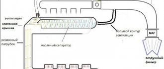
In the picture on the right is the crankcase ventilation system of the VAZ 2111 engine, which includes a breather:
- Crankcase.
- Breather.
- Hose from the breather to the valve cover pipe.
- Oil separator under the valve cover.
- A thin hose from the valve cover to the fitting with the throttle body nozzle.
- Fitting with jet on the throttle valve block.
- Thick hose from the valve cover to the intake pipe..
But the breather is installed not only in internal combustion engines. It is in:
- Gearbox. Otherwise, the gearbox would begin to operate jerkily, and the wear of the gears on the secondary shaft would increase many times over. Something similar is observed when the breather becomes clogged and ceases to perform its function.
- If the design of the car provides for a separate transfer case, then a similar mechanism may be in it.
- Front, and in rear-/all-wheel drive vehicles - in the rear axle. Moreover, this inconspicuous detail not only equalizes pressure, it protects the mechanisms from dirt and moisture when overcoming water obstacles.
However, even their appearance is often similar, and often identical: they perform the same function.
Malfunction: the crankcase ventilation system is clogged
Many car owners have a vague idea about the crankcase ventilation system of their car. Since for a long time, while the car has low mileage, it works unnoticed, without giving away its existence. After years and (or) hundreds of thousands of miles, the ventilation system gradually becomes clogged, showing the first signs of its malfunction.
Signs of malfunction: the crankcase ventilation system is clogged
Drives engine oil out of the engine under seals and gaskets
Since the ventilation system is responsible for the timely and effective removal of gases from the engine crankcase into its intake tract, the slightest narrowing of its channels due to the appearance of deposits in them leads to an increase in pressure in the crankcase and in the engine itself. Increased pressure causes engine oil to leak under the crankshaft and camshaft seals, pan gasket, valve cover gasket, and oil filler plug. Replacing oil seals and gaskets in such a situation does not solve the problem of oil leakage.
Engine air filter housing oil
(for carburetor engines)
Due to the reason described above for the increased pressure in the engine crankcase, the engine oil contained in it begins to be actively released along with gases under the valve cover and further into the air filter housing. Clogging the filter element and carburetor jets.
Increased engine oil consumption
Since engine oil begins to be actively released into the engine intake tract and burns out in the combustion chambers, its consumption increases accordingly. At first, almost unnoticeable, it gradually grows as the ventilation system becomes clogged.
Oiling of spark plug electrodes
Due to engine oil entering the engine intake tract and further into the combustion chambers, the spark plug electrodes become oiled. The spark plugs begin to work intermittently, the engine idles, there are dips and jerks in movement, and blue smoke from the muffler.
Causes of the malfunction: the crankcase ventilation system of the car engine is clogged
High car mileage
Sooner or later, the engine crankcase ventilation system ceases to effectively cope with its responsibilities since it constantly has to deal with crankcase gases carrying particles of oil, soot, etc. Over time, all this clogs the system’s oil separator and settles in the form of soot deposits on the walls its hoses and tubes.
Use of low-quality oils
The process of clogging of the crankcase ventilation system can be accelerated by constant operation of the car engine with low-quality and (or) engine oil unsuitable for the given engine. In this case, the amount of soot deposits increases significantly.
Wear of the engine piston group
A worn-out piston group of a car engine (rings, pistons, cylinders) allows a large volume of gases from the combustion chambers to break into the crankcase, increasing the pressure in it and contributing to the onset of negative consequences.
What to do if there are signs of clogging of the crankcase ventilation system?
Change the engine oil to an appropriate and high-quality one.
Check the compression in the engine cylinders to determine the degree of wear of its piston group.
Notes and additions
On engines in which the design of the ventilation system allows, there is a practice of eliminating the negative consequences of clogging of the ventilation system and piston wear, which consists of leading the main hose of the system under the engine. In this case, crankcase gases are released into the atmosphere. Since they are poisonous, the environment suffers.
Why is an engine crankcase ventilation system needed? The system is designed to remove gases from the engine crankcase into its intake manifold, which prevents an increase in their pressure and, as a result, oil leakage under the oil seals and seals. In addition, afterburning of harmful crankcase gases leads to a decrease in exhaust toxicity.
Closed crankcase ventilation system. With forced removal of gases (due to vacuum in the intake manifold). Gases are sampled through an oil separator, which cleans them of engine oil particles. Gases are removed through two circuits (main and idle).
Example: design of the crankcase ventilation system of a car engine.
1. Engine crankcase.
3. Hose from the breather to the valve cover pipe.
4. Oil separator under the valve cover.
5. A thin hose from the valve cover to the fitting with the throttle body nozzle.
6. Fitting with a jet on the throttle valve block.
7. Thick hose from the valve cover to the inlet pipe.
The second method of upgrading crankcase ventilation
The meaning of the following is to transfer the small ventilation circuit from the throttle part to the receiver, which helps reduce differences when switching modes. To complete this design, you will need to perform the following manipulations:
- The thin crankcase ventilation hose is disconnected from the throttle;
- The free end is connected to the free inlet fitting on the receiver, with preliminary removal of the plug;
- The free opening of the remote control is blocked by installing a plug;
- As a result, the flow of air mass increases, eliminating the possibility of a sharp response of the throttle valve to a jerk of the engine;
- In addition, crankcase ventilation increases and additional draft appears in the lower part of the mechanism.
Crankcase VENTILATION SYSTEM
The power plant of any car is a very complex device, including mechanisms and systems that interact with each other. At the same time, the engine is not a closed hermetically sealed circuit and it also has ventilation. Crankcase ventilation is a scheme that ensures the removal of gases from internal cavities. The fact is that during combustion of the working mixture in the cylinders, exhaust gases are formed, which are under pressure, due to which part of them penetrates into the sub-piston space - the crankcase, where it mixes with oil mist and moisture formed as a result of condensation. This whole mixture is called crankcase gases. If the engine were sealed, with an increase in the amount of gases in the crankcase, the pressure inside it also increased. Because of this, a breakthrough of gases along with oil through the breather, oil seals, seals or the hole in the oil dipstick is possible. Based on this, it follows that the main task of the ventilation system is to maintain pressure inside the engine and prevent it from exceeding the permissible norm by removing crankcase gases.
Changing the purge valve on Kalina
The replacement procedure itself is not a complex undertaking. To perform this, the owner will need to acquire a regular Phillips screwdriver and know where the valve is located.
Below we provide an algorithm of actions that allows you to quickly and efficiently complete this procedure.
- Disconnect the corresponding terminal from the negative terminal of the battery.
- You will need to disconnect the power connector from the valve itself.
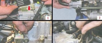
- For ease of access to the unit, we move the suction pipe of the intake system slightly to the side together with the “Max Air Mass Airflow” sensor. For this purpose, use the indicated screwdriver to loosen the clamp of the pipe and perform the action.
- Now we proceed to dismantling the unit. To do this, disconnect a pair of fittings located on the sides of the product. One of the fastening elements is fixed with a latch and to dismantle it, you will need to recess the latch, then lift the antennae and finally tighten the fitting to the side.
- Before installing a new component, we check that the markings on both valves match and make sure that they are identical.
- Installation and fixation of the product is carried out in the reverse order.
The canister purge valve has been replaced.
Cleaning the crankcase ventilation system
Over time, tarry accumulations of gases accumulate in the crankcase ventilation structure, which blocks their release into the engine cylinders for combustion. In this regard, the gas pressure increases, the oil gradually flows through the seals. To avoid this situation, keep the structure clean.
Helpful advice
Clean the crankcase ventilation after changing the oil.
To clean VAZ-21116, VAZ-11186 engines, take a “10” wrench, a Phillips screwdriver, and pliers.
1. Loosen the breather clamp of the large branch of the crankcase ventilation structure and unfasten it from the air supply hose.
2. Unfasten the other end of the breather from the pipe on the cylinder head cover and remove the hose.
3. In the same manner, remove the breather of the small branch of the crankcase fan structure. Unfasten it from the cylinder head cover and the intake module pipes...
4. ...and the inlet breather of the ventilation structure, unfastening it from the fittings of the cylinder block and the cylinder head cover.
5. Wash the breathers with gasoline. Clean all spans of pipes and fittings.
7. Unscrew the oil separator fixing bolts and remove the washers.
8. Unfasten the oil separator housing.
9. Remove the head screens from the block head.
10. Wash the grids, cylinder head cover, and oil separator housing thoroughly with kerosene.
11. Place the grids equally and fix them so that the grids rest against the bulges in the lid on one side, on the other...
12. ... the hole for fastening the bolt was visible. Place the oil separator housing and screw in the bolts.
13. Secure the cover to the block head.
14. Fix the structure’s breathers in the opposite order to disassembly.
To clean the crankcase ventilation structure of VAZ-21126, VAZ-21127 engines, do the following.
The work is depicted using the example of a VAZ-21126 engine. Identical work is carried out with the VAZ-21127 engine. The difference is in the intake pipe model.
Take an 8mm wrench, a screwdriver and pliers.
1. Unfasten the air filter.
2. Loosen the tie and unfasten the large branch breather from the air hose.
3. Having loosened the tie, unfasten the large branch breather from the cylinder head and remove it.
4. Using the same method, unfasten the breather of the small branch of the crankcase ventilation structure by removing it from the throttle body pipe and the cylinder head.
5. Loosen the tie, unfasten the supply breather of the ventilation structure from the cylinder head cover fitting.
6. In the same manner, remove the second end of the breather from the cylinder head pipe and unfasten the breather.
7. To connect the breathers, wash them thoroughly with kerosene and dry them, clean the pipes with compressed air.
9. Unscrew the 6 fastening bolts of the separator inside the cylinder head cover and remove it.
10. Grab the separator oil deflector fasteners with a clamp and remove it.
11. Carefully pry up the rubber ring using a screwdriver. Replace the ring that has lost its elasticity with another.
12. Secure the breathers and parts in the opposite order of removal.
Video
Tools:
- Open-end wrench 10 mm
- Open-end wrench 13 mm
- Open-end wrench 17 mm
- Medium Phillips screwdriver
Parts and consumables:
- Gasoline/kerosene
- Rags
- Sealant
- Automotive compressor
- Cylinder head cover gasket (if replacement is needed) -2108-1003270-10
Read more: Passing under a truck sign is prohibited, fine 2020
Notes:
The crankcase ventilation system of the VAZ Lada Kalina 1118 tends to accumulate tarry deposits from crankcase gases, which make it difficult to remove these gases into the engine cylinders for combustion. Because of this, the gas pressure inside the engine increases and oil leaks through the seals appear. We recommend cleaning the crankcase ventilation system before each oil change.
1. Remove the decorative plastic engine cover.
2. Loosen the clamp and disconnect the hose of the large branch of the crankcase ventilation system from the air supply pipe.
3. Disconnect the second end of the large branch hose of the crankcase ventilation system from the fitting on the cylinder head cover and remove the hose.
4. Similarly, remove the hose of the small branch of the crankcase ventilation system by disconnecting it from the fittings of the throttle assembly and the cylinder head cover.
5. Remove the supply hose of the crankcase ventilation system by disconnecting it from the fittings of the cylinder block and the cylinder head cover.
6. Rinse the hoses with gasoline or kerosene, blow with compressed air and dry. Clean the holes in the fittings and pipes for connecting the hoses.
7. Unscrew the two fastening nuts and remove the cylinder head cover.
8. Unscrew the long 1 and short 2 bolts securing the oil separator from the inside of the cylinder head cover and remove the washers.
9. Remove the oil separator housing.
10. Remove the mesh pack from the cylinder head cover.
11. Thoroughly rinse the screens, oil separator housing and cylinder head cover with kerosene.
12. Turn the grids in the bag so that they are oriented in the same way, and install the bag in the lid so that on one side it rests against the protrusions in the lid, and on the other side you can see the hole for the bolt that secures the oil separator of the VAZ Lada Kalina 1118.
13. Install the oil separator housing and tighten its mounting bolts.
14. Check the condition of the cylinder head cover gasket, replace if necessary.
15. The hoses of the crankcase ventilation system and the cylinder head cover of the VAZ Lada Kalina 1118 are installed in the reverse order of removal.
The article is missing:
- Photo of the instrument
- Photos of parts and consumables
- High-quality photos of repairs
If, while operating a LADA car, you notice that during load (when the air conditioner is running, the heating is on, etc.) in a traffic jam, the engine begins to operate unstably (troits, pulls poorly, etc.), perhaps the reason lies in the ventilation system crankcase The article proposes to solve the problem by installing a PCV valve from a foreign car.
Purpose of the adsorber purge valve
In the Lada Kalina model, as in principle in any other car equipped with distributed fuel injection, an adsorbing system is necessary to localize the resulting gasoline vapors. They accumulate inside the tank after the engine stops, and after a certain time necessary for the transformation of these vapors into a condensation state, they turn back into liquid fuel. The remaining volume of vapor that failed to return to the tank moves to the adsorber, where it is retained by two valves. The first (gravity type) is necessary to prevent fuel spillage when the LADA Kalina body turns over (in an accident, etc.), and with the help of the 2nd, the pressure indicator inside the tank is monitored.
see also
- Forced ventilation in plastic windows
- Automation of ventilation systems
- Plastic check valve for ventilation
- Installer of ventilation air conditioning systems, pneumatic transport and aspiration
- Ventilation for piglets
- Cutting shaped parts for industrial ventilation
- Museums art galleries heating ventilation air conditioning
- Aerodynamic ventilation tests
- Ridge ventilation for soft roofs
- How to make ventilation in the kitchen
- Fuel tank ventilation system
Alternative options
The next version of the improvement involves installing a hose with a small diameter into the crankcase ventilation circuit of the EPK valve of the “Cascade” model. In idle mode, the valve for standard exhaust gas outlet should be opened. Considering the fact that when installing the system in question, the supply of harmful impurities through the throttle valve stops due to the circuit opening. This is very important in the case of a transition of the engine operating mode from idle to light loads, when a lean air-fuel mixture is categorically unacceptable. Ventilation is carried out through the entire line, including the carburetor unit.
After further replacing the durite with a hose from the vacuum ignition advance device, it is reasonable to increase the diameter of the main jet of the first combustion chamber or simply reduce the input fuel flow to 4.5 mm. The scheme under consideration was tested on a model of the domestic VAZ 2101. At the same time, the following positive aspects became noticeable:
- The pedal drop during acceleration has disappeared;
- The engine's operation became smooth;
- There are no intermittent oscillations at idle.
Let's sum it up
The work of replacing the valve is simple, however, when the owner of a Lada Kalina is not confident in his capabilities or does not show the desire to carry out repair operations in such a high-risk unit as the fuel supply system, we recommend using the services of a specialized workshop.
The car's EGR Exhaust Gas Recirculation system is a very vague and rather capricious thing, especially with the very low quality of fuel that is found in our area, quite often. The ambiguity of this system lies in the fact that its purpose is purely environmental. waste recycling system
gases or USR, is designed to reduce the amount of nitrogen oxides in the car exhaust. What is the USR, why is it needed and how its malfunctions are expressed, we will talk about all this for now.
Modification of the crankcase ventilation system Kalina 8 valves
This system could be improved a little. One of the 3 pipes supplies crankcase gases directly to the throttle valve assembly next to the IAC. If they contain oil, it will definitely settle there. This is how the IAC becomes clogged. So, to avoid this, you can embed a regular fuel filter right in the middle of this pipe.
It will trap oil particles contained in crankcase gases. After a few hundred kilometers, you will see for yourself. Monitor the condition of this filter and promptly change it to a new one. On average, as practice shows, it needs to be changed every 1000 kilometers.
USR system management
recirculation system is controlled by the electronic engine control unit. And the command to open or close the EGR valve can be given based on:
- coolant temperature sensor;
- crankshaft sensor;
- throttle position sensor;
Read
In various car models, either all of the listed sensors are used to control the USR valve, or some of them, and in some cases, only the coolant temperature sensor.
What does the EGR valve look like on a Chevrolet Lacetti?
One way or another, the operation of the USR valve is always controlled by automotive electronics. And while this system functions normally, the driver practically does not feel its operation at all. The useful work of the USR system outside of environmental issues is very unnoticeable. This system allows you to save about three percent of fuel on gasoline engines. Also, in some cases, the USR system prevents fuel detonation in the engine. But this phenomenon in itself is rare and extraordinary. As for diesel units, if they have a properly functioning EGR system, they operate more smoothly, softly, and quietly. In addition, in diesel engines, the formation of soot is reduced through the USR. That's all the bonuses that the exhaust gas recirculation system provides the owner.
What is an EGR valve and what is an exhaust gas recirculation system for?
REAL TAXI DRIVER A huge flaw in the design.
EGR (Exhaust Gas Recirculation) System - Evil or Good?
In this video I explained in Russian why the EGR valve is needed
, but to jam it or not, draw your own conclusions.
Troubleshooting
- The first thing you need to pay attention to is the color of the exhaust, blue or black smoke, a sign of burnt valves or problems with rings.
- Next, you should check the compression in all cylinders. The value on gasoline internal combustion engines should be within 11-13 MPa.
- Disconnect the pipes from the valve covers, air vent and breather. Assess the degree of contamination. If the pipes are very dirty or clogged with oil deposits, use gasoline to clean them or a special carburetor cleaner.
- Check the condition of the oil separator. Unscrew the required bolts to get to this unit. Remove the oil separator and assess its condition. If necessary, clean or rinse followed by drying.
- Inspect and, if necessary, flush the breather valve. There are situations when the valve gets stuck, resulting in exhaust gases entering the crankcase and creating excess pressure. Remove the part and wash it; in most cases, this will resolve the issue of squeezing oil out of the breather.
Helpful advice! To distinguish stuck rings from a burnt-out valve, it is enough to perform several manipulations. After checking the compression in the cylinders, determine the cylinder with the lowest value. Then inspect the spark plug of this cylinder; if the rings are lodged in this cylinder, the spark plug will be covered with a thick oil layer. If the valve is burnt out, the spark plug will appear normal without any major abnormalities.
Finally…
The problem of oil escaping through the breather worries many motorists and causes a lot of trouble, but if the problem is detected in a timely manner and the right approach is taken, serious consequences can be avoided. It is important to ensure that the oil level is normal; as soon as you find that the engine is taking oil, monitor its level and constantly monitor it so that it does not fall below the permissible level. Also pay attention to the breather and filter; oil on the air filter in large quantities also does not bode well. Regularly monitor the condition of the engine and all systems, and also promptly correct any malfunction. This will save you from engine overhauls and unnecessary waste.
Source
Possible heater malfunctions
Your stove is not working or is not heating well. Look for the cause of the problem. The fan does not work or the heater radiator is leaking - obvious breakdowns that occur at any time.
Stove control unit:
- The engine was warmed up, but warm air did not enter the cabin.
- The damper drive cables may have come off. The only solution is to remove the console.
Dampers. Partially open or close. The rubber seal has come off in the air duct or foreign objects have gotten into it.
Antifreeze circulation. Start the engine and check the level in the expansion tank, and also check for any disturbances in the normal flow of antifreeze. Possible reasons:
- Pump. Cannot be repaired, only replaced.
- The cooling system is clogged. Clean or rinse.
Checking the thermostat. Warm up the engine to 75°C. If the upper pipe is cold, then the thermostat does not work correctly and does not allow coolant to move in a large circle. Replace the device.
Airlock. Remove the plug from the vehicle's engine cooling system.
Temperature sensor. Constantly blowing cold or hot air. If cleaning the contacts does not help, then replace the non-working temperature sensor.
Air filter. If the air flow is weak and there is no desired temperature, then replace the filter. Be sure to check the heater resistor, which controls the rotation of the fan and is located under the glove compartment.
Electric fan. The device does not turn on regardless of the selected mode. Check the fuse that controls operation. If the fan is turned on and its operation is accompanied by strange sounds, clean or replace it.
Dampers. It is difficult to determine the breakdown unless you replace the dampers themselves.
The cause of a heater malfunction may be a depressurization of the car's engine cooling system. The types of breakdowns described above cause malfunctions in the operation of the Lada Kalina car's stove. Such breakdowns do not require special knowledge; they are easy to understand and repair.