If your Starline alarm system does not work, we will help you find the source of the problem.
All types of faults can be divided into 3 large groups:
- The key fob does not work;
- The central control unit is faulty;
- Problems are associated with the influence of external factors (body parts, battery, wiring, radio interference, etc.).
Next, using Starline a91 as an example, let’s look at why the alarm system on your car stopped working.
First of all, eliminate the following problems (which, with a timely approach, are not problems at all);
- If the car stood idle for a long time, the alarm could glitch due to a dead battery. Or his contacts could have oxidized;
- Starline false alarms are most often associated with the need to reduce the sensitivity of shock sensors. The action is performed from the key fob, the algorithm is in the technical manual;
- The key fob, as usual, ran out of battery. Change;
- The control panels must be registered new (instructions in the manual).
Next, we move on to a detailed review of the reasons why the Starline alarm system in a car does not work (or does not function correctly).
Troubleshooting
Main symptoms of problems:
- lack of response of the alarm to commands sent from the remote control;
- the alarm siren goes off for no reason;
- after turning on the security mode, the alarm does not close one or more doors.
Problems with the power system
Problems of this kind can be associated both with the operation of the communicator and with the functionality of additionally installed equipment. The presence of voltage drops in the electrical network can ultimately lead to breakdown of the main control module. If there is no power, the anti-theft complex will be de-energized as the battery is discharged.
Signs of such a problem include the alarm not responding to commands sent from the remote control. This malfunction may be due to the battery installed in the device being discharged, this will lead to the display and indicator light turning off. If the battery is low, this will also reduce the operating range of the communicator. You need to diagnose the battery using a multimeter, and also check the status of the power source in the key fob.
Problems with electrical wires
Long-term use of the anti-theft complex, as well as temperature changes and moisture lead to wear and oxidation on the contact elements of electrical circuits. Because of this, voltage will not be able to pass through the power lines, the same thing happens when the circuits break. The reason is often related to the connection of additional equipment and electrical appliances, as well as an attempt to steal a car. Electrical problems are often caused by broken fuses.
Symptoms of a malfunction include a lack of response to commands sent from the remote control, although the communicator itself will be in working order. Diagnostics of the wiring is carried out with a multimeter; it is necessary to check each electrical circuit connected to the microprocessor unit.
Program failure on microprocessor device
Firmware problems will lead to incorrect functioning of the complex. The car alarm may turn on the alarm mode for no reason, and also not respond to sending commands from the communicator. Unreasonable blocking of the power unit is possible. You will not be able to detect this problem on your own.
Unreasonable activation of the siren
In reviews, motorists often complain about such a problem as the siren going off for no reason. In practice, malfunctions of this kind are usually caused by mistakes that the consumer made when installing and adjusting the operating parameters of the alarm. The user could incorrectly set the sensitivity of the shock sensor, as a result of which the alarm reacts to passing cars and animals.
If the sensitivity is too high, the siren may be triggered in response to loud sounds and wind. Incorrect operation of the shock sensor is due to its incorrect installation, for example, the user used a plastic or rubber gasket between the device and the surface of the body. In accordance with the instructions for a specific model, the sensitivity of the sensor is diagnosed.
Malfunctions in the communicator
If the device fails or functions incorrectly, the microprocessor device will not be able to receive signals from it. The problem is due to wear or mechanical or software problems. The device may have been dropped or water may have been spilled on it.
Incorrect operation at low temperatures
In winter frost, the electrolytes in the battery move more slowly, resulting in power problems in the on-board network. This is especially true in northern regions, where air temperatures may be lower than those allowed by the manufacturer.
Pakha Blue showed a “glitch” in the operation of the Starline anti-theft system.
Problems with the key fob
Immediately check whether the connection with the key fob works - when arming or disarming, the display on the screen changes according to the operation performed, regardless of whether the door locks are activated. If the alarm does not recognize commands from the key fob, then refer to the article we published about mechanical problems with StarLine key fobs; the key fob may need to be repaired or replaced.
How to repair it yourself?
If the feedback signal A91, A61 or another model does not work in the car, then you can try to diagnose the problem yourself.
If a problem is detected, repairs are carried out as follows:
- It is necessary to visually assess the condition of the main communicator for possible damage. Make sure there are no traces of moisture inside the case; to do this, the device must be disassembled. There should be no traces of condensation on the inside; if there are any, the remote control should be thoroughly dried. To get rid of traces of liquid, place the faulty device next to a household radiator or in the sun, next to any heat source. Don't forget that long-term exposure of the board to UV rays can lead to more serious problems.
- If there are no traces of liquid inside the device, the reason may lie in the presence of electromagnetic interference in the area. With this problem, the alarm does not work when the user sends commands to it from the communicator. Try to bring the pager as close to the transceiver as possible; if you can’t unlock the doors, click on the open button. If the A61 alarm or another model does not respond, then you need to replace the power supply in the communicator.
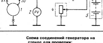
- If these actions do not produce results, then it is necessary to diagnose the power supply. To complete the task you will need a tester. The battery terminals are first cleaned of dirt and traces of oxidation. The multimeter probes are connected to the battery outputs in the engine compartment, then the engine is started. After the start, the tester display will display digital values, ideally they should be in the range from 13.5 to 14 volts.
- If the diagnostics showed that the voltage in the on-board network is 14.2 volts, this indicates a decrease in battery charge. The generator set operates in enhanced mode to replenish the battery charge. If after starting the engine the voltage is less than 13 volts, this indicates that the battery is not receiving enough charge. Disconnect all electrical equipment installed in the machine and check the parameter again, before checking, make sure the terminals are in good condition. Often the lack of charge is due to the absence or insufficiency of electrolyte inside the device; in the absence of liquid, its volume is replenished with distilled water.
- If the battery is normally charged, all power lines connected to the microprocessor signaling device are checked using a tester. The user should ring all contact elements; it would be useful to perform a visual check of the wires for integrity. If all electrical circuits are intact, then you need to diagnose the fuses. Damaged devices are replaced, the same goes for wires. We recommend additionally wrapping new electrical circuits with electrical tape to prevent rapid wear and damage.
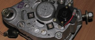
- If the diagnostics do not show the cause of the failure, the microprocessor unit, that is, the main module, is checked. The device must be dismantled and the housing must be visually inspected. If damaged contact elements are found on the plug, the connector is completely changed. The housing of the microprocessor unit is disassembled to diagnose the presence of traces of moisture inside. If there are traces of water, they are removed in the same way as on the communicator. Oxidized contacts must be cleaned with a brush. If there is no damage or traces of moisture, the cause is a malfunction in the software. It is necessary to perform an electronic check of the module; it may require flashing and resetting the unit.
Alexander Shestopalov spoke about diagnosing the car battery and generator set using a tester.
It is not recommended to repair a microprocessor device yourself; it is better to trust professionals for a high-quality result.
How to identify and change a dead battery in a key fob
The first thing you need to do when the alarm key fob does not work is to pay attention to the state of its battery, the insufficient charge of which is not able to ensure full signal transmission to the security system unit and, accordingly, it will not operate. You can determine the state of charge of the power supply by the dimming screen of the key fob or on the corresponding indicator icon. This malfunction can be eliminated by replacing the battery, after which the key fob can be fully used. It is changed using a small screwdriver, which is used to unscrew the screw connecting the halves of the key fob to each other. Having unscrewed the screw, the key fob is carefully disassembled and access to its power element is opened, which must be picked up and pulled out from the workplace, installing a new one there, and reassembling in the reverse order.
What to do if the alarm key fob does not work?
Malfunctions in the key fob can be corrected yourself.
Removing contaminants
Algorithm for cleaning the Starline signaling console:
- Using a cotton swab soaked in an alcohol solution or a damp cloth, clean the communicator body. This must be done in order to prevent contamination from entering the device during its disassembly and repair.
- Open or unscrew the back cover of the device, depending on the type of mount, and remove the battery from its mounting location. Using a soft brush, the battery seat is cleaned and all dust is thoroughly removed. If there is oxidation on the contact elements, use an alcohol solution, but it must be applied carefully, moistening a cotton swab.
- The key fob body is being disassembled. On the back cover there should be bolts that secure the two parts of the case; they are unscrewed with a screwdriver with a small blade and removed to the side. Parts of the case are disassembled, and the inside of the device is cleaned from dust. To clean, use a brush or cloth.
- Perform a visual diagnosis of the microcircuit installed inside. If there are traces of contamination, it is cleaned. To do this, you will need a cotton swab, the end of which is treated with alcohol. There should be little liquid so as not to flood the board. Any dirt and acidification is removed.
- When cleaning is completed, the case is assembled, the steps are performed in the reverse order. Connect all elements correctly, in particular, this applies to control buttons. When the device is assembled, it is tested.
Replacing the case and display
If the screen or case breaks, it will be difficult to find new parts. You can purchase a new pager on the market or in stores, but the manufacturer does not supply the components for sale. Therefore, it is advisable to look for a screen and housing on the secondary market or on the Internet.
Before performing repairs, do the following:
- The battery is removed from the control key fob; the back cover is removed to remove the battery.
- Use a small bladed screwdriver to unscrew the screws that secure the two parts of the housing. The back cover is removed and the buttons are removed from the communicator.
- If the display is broken, then this is not such a serious problem. It is much worse if its fragments damage the microcircuit. Remove the board by disconnecting the latches; the circuit is pulled out of the housing with the transceiver module. To dismantle the display from the microcircuit, you need to disconnect the LED backlights. Carefully, using a screwdriver or a utility knife, the graphite cable is disconnected from the board contacts. The cable is flexible, be careful when removing it.
- The microcircuit contact is cleaned. Then take the new screen and attach it to the body of the device, making sure that its dimensions correspond to the standard.
Roman Marketov demonstrated the procedure for replacing the screen on a Starline communicator.
Algorithm for repairing a communicator:
- First, wire needles must be attached to the contact legs, after which they are soldered. Repair of key fobs is carried out using a soldering iron equipped with a thin tip; its use will allow you to equip the so-called. bridges on the board. If your soldering iron is equipped with a thick tip, then before starting work you need to connect a piece of copper wire to it.
- Since the screen was removed, it must be installed back and securely fastened to the device body. Be careful at this stage; if you act carelessly, you can cause a complete failure of the communicator. Glue must not get on the display; it must be carefully applied only to the end components of the spare part. The screen is then fixed to the frame. If glue gets on the display, it must be cleaned immediately before it dries. Otherwise, a mark will remain on the screen.
- The board is being installed into the device case; at this stage there should be no problems. If the housing is changed and a new one is installed, then you need to make sure that the new spare part has holes for fastening. Sometimes plastic pins are located in the body of the replacement device to secure the two parts. If they should not be there, then they are removed with a stationery knife.
- When the two parts of the case are secured, installation and tightening of the screws is carried out; a screwdriver is required for this. After assembly, diagnostics of the key fob operation is carried out, and batteries are installed in the device. Once turned on, all icons and indicators should appear on the screen. The car alarm must respond to all commands sent by the user.
The Auto Launch channel demonstrated the process of repairing the communicator and replacing the screen with a cable.
Button repair
Key changing algorithm:
- The back cover of the communicator is removed and the battery is removed from the device body. There is a small bolt under the battery that can be unscrewed with a screwdriver. The bolt is retracted to the side; it must not be lost. There is a sticker in the seat for the battery; it must be removed, since there may be bolts under it. If they are, then they need to be unscrewed.
- The rear component of the device is being dismantled. When the two parts of the case and the microcircuit are in your hands, you need to diagnose the keys. If these elements are worn out and need to be replaced, their fixation will be weak.
- The worn key must be dismantled and removed. The main part of the communicator is installed on a flat and clean surface, for example, on a table, with the display facing down. There is a spring inside the device, it is used as an antenna module. If it is, then difficulties may arise during the soldering process.
- The communicator button has 4 contacts, they are installed in the corners, and plastic feet are also located here. The latter perform the functions of guides and are installed in the lower part; technological holes are provided for their installation on the board. To complete the fixing task, you will need glue and a toothpick, as well as tweezers, which will be used to fix the key. The legs of the new button are treated with glue, after which the part is fixed on the board.
- When the glue dries, you will need a soldering iron with a thin tip and tin, using the tool to solder the contacts. They are fixed at the corners of the diagram. Work carefully; at this stage it is important to ensure good contact between the key and the board.
- The remote control chip is mounted on the front component of the device body. The bolt is installed in place and screwed. We recommend inserting the bolt while hanging, since once the housing elements are connected, its installation will be difficult.
- The body parts are attached to each other using glue, then the bolt is tightened until it stops. The fasteners snap into place, the battery is installed in place, then the lid is closed.
- The communicator is activated and the time parameters are configured. This is important to do if you plan to use the remote start feature at a specific time. To synchronize the operation of the pager with the microprocessor unit, you need to press lock the door locks. Check all the buttons on your communicator.
Analysis of the component parts of the case
Identification of contacts and guides on the key
Why does the security system go off for no apparent reason?
One of the most common problems of many security systems and, accordingly, the A91 is that the alarm goes off on its own for no apparent reason, which is due to the increased sensitivity of the so-called shock sensor, which has several settings and is located in the vehicle interior. To carry out independent diagnostics of the sensitivity of the sensor settings, it must be turned off, for which you will need to perform the following steps:
- On the key fob with the display, press button No. 1 with a short double press, after which the car’s headlights should blink twice, and the key fob will emit a short sound melody and display on the icons the shutdown of signals from the shock sensor, called the first level.
- Next, the second level of sensor adjustment is turned off, to do this you need to press button No. 1 on the key fob twice again, after which the car’s head optics should blink three times, and the key fob should emit three short beeps and display icons for temporarily turning off the shock sensor on the display.
What is the price?
Starline car alarm repair prices vary depending on the city of residence and the model of the anti-theft system.
How much will it cost to repair the alarm system yourself?
| Name | Price, rub |
| Microprocessor device repair | From 300 to 3000 rubles depending on the nature of the breakdown |
| Diagnostics and repair of wiring | From 200 rubles and more, depending on the severity of the damage |
| Reflashing the control unit | From 500 rubles and above, depending on the model of the microprocessor device |
| Prices are relevant for three regions: Moscow, Chelyabinsk, Krasnodar. | |
How much will it cost to repair the key fob?
| Name | Price, rub |
| Communicator repair | From 200 rubles and more, depending on the model of the anti-theft system and the nature of the damage |
| The price is valid for three regions: Moscow, Chelyabinsk, Krasnodar. | |
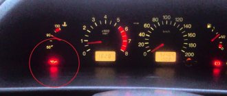
The brake icon on the key fob lights up
Before you figure out why the brake on the alarm key fob is on, you need to find out how the alarm itself is connected (by wires or via a CAN bus) and where the brake control circuit is connected. This could be the reason.
If control was set using the stop pedal, then the problems may be associated with:
- burnt-out incandescent lamps in the lanterns at the stern. After replacement everything should go fine.
- Poor mass in the lanterns. Only an auto electrician can fix this problem.
- With the CAN bus falling asleep, this is the case when a CAN adapter is installed together with the alarm system.
Where can I repair it if I can’t do it myself and how much does it cost?
To repair a Starline car alarm, you can come to the service station yourself; many services today offer the service of calling a specialist. The cost of a call, depending on the station, can average from 500 to 2 thousand rubles.
Costs by region are shown in the table:
| Region | Price | Firm |
| Moscow | from 2000 rub. | "Auto diagnostic" |
| Chelyabinsk | from 1500 rub. | "You Do" |
| Krasnodar | from 500 rub. | "Key Auto23" |
Video
An overview of Starline errors is provided by a video filmed by the author Roma Vug.
Security systems use a diagnostic system that displays an error code on the communicator display. The error “OS 7” displayed on the Starline remote control display (incorrect designation; the text “OST” is activated on the display, in which the letter “T” visually resembles the number 7) indicates a malfunction in the automatic engine start module.
Measures taken in the absence of startup
The siren will sound and the emergency lights will turn on at certain intervals.
Starline deactivation is complete.
Start the engine.
When installing an alarm system with auto start on modern cars, you should use the immobilizer bypass method. How does it work? The ignition key contains a transponder with an RFID tag. The immobilizer module communicates with the engine control unit and transponder via an antenna. By generating signals and decoding them, we begin to compare them with a given code. When the codes match, the engine start ban is lifted.
Bypassing the immobilizer is necessary to enable automatic remote engine start without a key with a transponder in the ignition switch.
Door locking when driving
With the ignition off, press the Valet service button five times;
When you turn on the ignition, the car beeps five times and lights up;
How to disable door lock
by briefly pressing the second and third keys, select the appropriate programming table (SF);
- The third button is pressed continuously and then briefly until a beep sounds;
- the corresponding function No. 12 is selected and parameter No. 4 is set;
- The parameters are output and saved automatically; you just need to turn off the ignition.
- The immobilizer relay is supplied with the alarm and is connected separately via additional channel 5.
- There are several ways to disable the starter lock on your security alarm system.
- Replace the control panel power element. After this time, the signals will become stronger, and the transceiver will be able to receive them without distorting the dialogue code;
through the Valet service button and a standard key. In this case, the alarm functions are disabled in the emergency mode described above;
Locking relay price
Data exchange between the immobilizer and the ECU occurs via K-Line, so it can be disabled by simply connecting the scanner to the diagnostic unit with the ignition on.
The fact that it was an external alarm blocking the engine from starting can be determined by a flashing control indicator, information on the monitor remote control, continuous operation of hazard lights (parking lights or headlights), freezes and inoperability. remote control buttons and buzzer operation.