If you want to say thank you to the author, just click the button:
Each hydraulic system, in addition to the pump, actuating hydraulic motors and hydraulic distribution equipment, contains valves. The number of valves, depending on the complexity of the system, varies from a few to several dozen, and in some cases their number is measured in hundreds. This article will describe the main types of valves most commonly found in hydraulic systems:
- Safety valves
- Reducing valves
- Check valves
- Controlled check valves
- Brake (counterbalance) valves.
Basic principle of valve operation
The principle of operation of the simplest valve is to balance the force created by the pressure of the working fluid on the seat area and the elastic force of the spring. The valve seat is a structural element that forms a working edge that ensures a tight fit of the shut-off element. The simplest valve has the design shown in Figure 1a. In the body 1 there is a working edge, to which the locking element 2, pressed by the spring 3, fits tightly. The force created by the spring 3 determines the pressure difference between the cavities P and T at which the valve opens. Figure 1b shows the valve in the open state, where the arrows indicate the direction of movement of the working fluid. Two-stage valves, depending on their purpose, can have different designs and will be discussed below.
Classification
There are several types of valves based on the type of shut-off element. The most common are: spherical (ball), conical, flat (see Figure 2). Due to their high sealing properties and manufacturability, spherical (ball) and conical valves are most widely used.
By installation method
There are valves of cartridge, pipe, butt (flange) and modular installation. Cartridge valves are further divided into screw-in (threaded) and embedded. There is another category - frameless valves. Frameless valves are typically a collection of valve components designed to be installed in a valve plate or body.
Cartridge and frameless valves can be used in a hydraulic system only as part of a valve block or installed in an individual housing. In Fig. 3, using the example of a valve block, cartridge and frame valves are shown before installation and in the installed state.
Pipe mounted valves have threaded ports for connecting hydraulic lines. Butt-mount valves are usually designed to be installed directly on a hydraulic unit (for example, a hydraulic cylinder or motor) and are secured by a group of threaded fasteners. Pipe and butt mounted valves are shown in Fig. 4. and fig. 5.
The subgroup of butt-mounted valves includes modular hydraulic equipment SETOR (see Fig. 6). Depending on the maximum flow of working fluid, the equipment is divided into several groups: CETOP 02, 03, 05, 07 and 08. The list of CETOP components includes a whole range of hydraulic components: these are all kinds of valves, hydraulic valves, flow control equipment, and even filtration of working fluid. All elements are mounted in groups or individually on mounting plates. An example of assembling a hydraulic system based on the CETOP 03 element base is shown in Fig. 7.
Safety valves
The safety valve is a short-term pressure control valve. It is installed in the hydraulic system to limit the maximum possible pressure in the line. Each hydraulic system has a safety valve in the high pressure line leaving the pump. Safety valves can be installed in lines where the pressure must not exceed a specified value. For example, safety valves are installed in the supply line of hydraulic motors to limit the pressure in them and, as a result, limit the maximum force generated by the motor. In addition to those mentioned above, safety valves have many typical applications.
According to GOST 2.781-96, safety valves on the diagrams are designated as shown in Figure 8.
In circuit designs, a safety valve can be used to ensure a minimum specified level of pressure or backwater in a hydraulic system line. In this application, safety valves are usually called retaining valves, which reflects the nature of their operation.
The design of a direct-acting safety valve is shown schematically in the figure. 9. A conical locking element 2 is installed in the body 1, pressed against the seat by a spring 3. The spring is adjusted with an adjusting screw 4. The locknut 5 is used to fix the adjusting position of the screw. The movable spring support 8 is sealed along the gap with the body 1. The closed volume 6 and the gap 7 act as a vibration damper for the valve shut-off element. Direct acting valves have a high response speed, which is their main advantage. Disadvantages include unstable operation and a tendency to self-oscillation. Also, as operating costs increase, the valve size also increases significantly.
Indirect-acting valves, which are often called two-stage or servo valves, do not have such disadvantages. The design of such a valve is shown in Figure 10. The main locking element 2 is pressed to the body seat 1 by a spring 9. The locking element has a throttle hole 3. The working cavity is separated from the drain line T by a pilot valve with a locking element 4, pressed to the seat by a spring 5. Adjustment mechanism The spring preload consists of an adjusting screw 7 with a lock nut 10, a support 6 and a seal 8.
The valve operates as follows: when the pressure in line P is below the valve response setting, the pressure levels in the working cavity and line P are the same, the main shut-off element is pressed against the seat by spring 9. The initial positions of the valve elements are shown in Figure 10. When the pressure reaches the pilot setting value valve, the latter opens, and the working fluid, passing through throttle hole 3, rushes into line T. When the working fluid passes through the throttle hole, a pressure difference is created between line P and the working cavity. This pressure difference acts on the locking element 2 and, overcoming the force of the spring 9, moves, which leads to the opening of the main valve.
How does a brake valve work?
Brake valves are designed to ensure smooth operation of hydraulic motors and hydraulic cylinders, limiting the speed of movement of actuators under the action of a passing load.
In lifting mechanisms, when lowering a load, the load acts in the same direction as the hydraulic motor. Under the influence of the load, the liquid will be forced out of the hydraulic motor at high speed, as a result of which the actuator can move very quickly, which can lead to shocks, breakdowns, and accidents.
In order to limit the speed of movement of the actuators, brake valves are used.
Working principle of brake valve
Consider the design of a one-way brake valve.
A spool is installed in the valve body, which is acted upon by a spring; the preload force is adjusted by a screw. Under the action of the spring force, the spool moves to the right (according to the diagram), the belt on the spool blocks the channel for fluid movement. pressure from the control line acts on the opposite end of the spool; under the influence of this pressure, the spool moves to the left (according to the diagram), tearing off the channel for fluid flow.
Consider the operation of a brake valve in a hydraulic system.
We will install the valve in the line connected to the rod end of the hydraulic cylinder; it will operate when the load is lowered. The control line must be connected to the fluid supply line to the piston cavity.
If there is no pressure in the piston cavity, the brake valve spool under the action of the spring will block the flow area, the liquid will not be able to flow out of the cylinder rod cavity, the rod will remain in place. When the distributor is switched, the liquid from the pump will enter the piston cavity, under the influence of pressure in the control line the brake valve spool will move, opening the flow area, the liquid will begin to flow out of the rod cavity, and the load will begin to lower. But it will not be able to accelerate significantly, since as the speed of its movement increases, the pressure in the piston cavity of the cylinder, and therefore in the control line, will fall, which will cause the spool to move and the passage gap to decrease, which means an increase in resistance to the exit of liquid from the rod cavity. That is, the liquid flowing out of the rod cavity will be inhibited, this will limit the speed of the rod movement.
To ensure that when liquid enters the cylinder cavity when lifting a load, it bypasses the brake valve, install a check valve parallel to it.
In industrial brake valves, the check valve is located directly in the spool.
Two way brake valves
If two brake valves are installed symmetrically in the housing, it becomes two-way and can be used to limit the speed of movement in two directions.
To supply fluid to the control channel, we will make a through channel in the spool; to separate the control channels, we will place a separating valve.
When pressure is supplied to the right channel (according to the diagram), the valve, under the influence of pressure, will be pressed against the end of spool 1 and the pressure will exert a control effect on this spool.
Let's consider the operation of a two-way brake valve using the example of a hydraulic drive of rollers.
When rotating clockwise, fluid from the pump will flow to the hydraulic motor. If the associated load begins to accelerate the hydraulic motor, the pressure in the control line will decrease, under the action of the spring force, spool 1 will shift, reducing the size of the gap through which the liquid flows, the resistance will increase, which will limit the speed of liquid outflow, and therefore the frequency of the hydraulic motor shaft.
Source
Checking the operation and replacing the vacuum booster check valve
Step-by-step instructions with photo accompaniment on how to check the operation of the check valve of the vacuum booster and replace it.
Step-by-step instructions with photo accompaniment on how to check the operation of the check valve of the vacuum booster and replace it.
If the first symptoms of poor performance appear with the brake system, then an inspection should be performed to find faults. Usually the first symptoms appear when you press the brake pedal. And this, in turn, is a malfunction of the vacuum brake booster - the main “assistant” of the entire braking system.
To check the functionality of the vacuum booster, with the car engine turned off, you need to make 5-6 consecutive presses of the brake pedal with an interval of 1-2 seconds and do not release the pedal for the sixth time - hold it pressed. Now, in this position, start the engine, the pedal should move forward. If nothing happens, then you need to check the vacuum hose and the operation of the check valve for leaks, which is what we will now do in this article.
The whole procedure is very simple and does not require additional outside help; everything can be done in the garage with your own hands. The most inconvenient and tedious thing is dismantling the trim under the hood, otherwise you won’t be able to get to the vacuum brake booster.
Vacuum booster functions
The main functions of a vacuum cleaner (a common designation for a device) are:
- an increase in the force with which the driver presses the brake pedal;
- ensuring more efficient operation of the braking system during emergency braking.
The vacuum booster creates additional force due to the resulting vacuum. And it is this amplification that, in the event of emergency braking of a car moving at high speed, allows the entire brake system to work with high efficiency.
Checking the operation and replacing the check valve of the vacuum booster:
1. Disconnect the wire with the “–” terminal from the car battery.
2. Remove completely the left and right noise-insulating upholstery of the engine compartment.
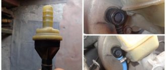
3. Inspect the vacuum hose for tightness of the connection with the fitting on the inlet pipe. If everything is fine here, then we move on.4. Check the connection of this hose at the other end - at the vacuum brake booster.
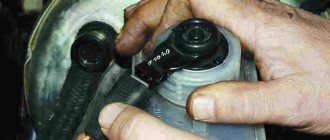
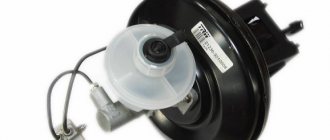
5. Here you need to loosen the clamp on the hose with the valve and remove it, after which the check valve can be removed from the vacuum booster.
6. You need to put a rubber bulb on the valve from the side of the large diameter fitting (the end that was inserted into the brake booster) and squeeze it. If everything is in order, then the air will calmly come out from the other side - through the valve.
7. If, when opening the pear, it remains in a clamped position, then the check valve of the vacuum brake booster is corrected. If air does not come out from the back side or the pear takes in air after opening it by hand, then the valve must be replaced with a new one. Replacement and assembly occurs in the reverse order.
This procedure can be done without a pear - blow through your mouth. Air should be freely blown out from the back of the valve and it should not be possible to blow into itself.VAZ
Source
Signs of problems
The vacuum brake booster and its causes of malfunction are divided into three types.
Let's list them:
Check valve failure.
Loss of tightness of the vacuum chambers.
Depressurization of the pipeline.
It turns out that VUT only has three problems, and problems with operating valves occur very rarely. If the amplifier fails completely, the car will still be able to drive. But in this case, the driver will have to make every effort to stop the vehicle. That is why the VUT should be checked while the car is started.
What is a brake booster valve
Many cars use a vacuum brake booster to increase braking force. It creates a constant flow of brake fluid into the master cylinder, increasing brake pressure and helping the vehicle stop faster. This element is very often found on cars, SUVs and pickup trucks. Over time, the brake booster can become damaged or wear out. The same thing can happen with the brake booster control valve.
Vacuum brake booster - how to diagnose a malfunction
Diagnosing a faulty vacuum brake booster is not difficult; it becomes noticeable - when pressed, the brake pedal becomes hard. But an indirect sign of a malfunction can also be a change in idle speed when the pedal is pressed . This is due to a lean fuel mixture caused by “excess” air entering the engine cylinders, which may even stall if the “suction” is too strong.
Most often this is due to damage to the brake booster diaphragm. And it’s not necessarily due to old age - sometimes the sealing rings of the main brake cylinder leak brake fluid, and it gets into the booster housing.
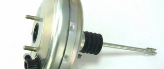
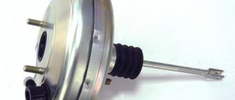
New vacuum brake booster for VAZ 2109
Some car owners manage to rebuild the brake booster themselves - they even sell repair kits for domestic cars. But, in general, this is a thankless task - the body of the “vacuum generator” is non-separable, and not everyone can carefully and tightly connect its parts.
In addition, the operation of the brake system is also affected by adjusting the protrusion of the “vacuum rod” from the housing - incorrect adjustment can reduce the efficiency of the booster or cause incomplete “release of the brakes” of the working brake cylinders. This method of checking the amplifier is common among car enthusiasts - start the engine after squeezing the brake. When starting the engine, the pedal should go to the floor.
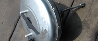
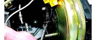
The process of removing the vacuum brake booster
If the booster is faulty, the brake pedal will remain “stiff”. In general, hissing associated with the operation of the vacuum brake booster is normal. But in the case when its volume increases for no apparent reason, get ready to replace the vacuum amplifier before it completely fails.
Symptoms of a problem
- Stiff brake pedal when the engine is running.
- When you press the pedal, the engine starts to rev, and when you slow down sharply, it stalls completely. The described symptom of malfunction is typical for cars in which the vacuum for VUT operation is taken from the intake manifold. If the membrane or vacuum tubes are not sealed, when you press the brakes, unaccounted air will be sucked in, so the engine stalls and begins to stall. The described symptom of VUT malfunction does not apply to cars in which the vacuum is created by a vacuum pump.
How to check?
A torn diaphragm is the main cause of vacuum brake booster failure. The operating principle of the amplifier is based on the difference in pressure in the vacuum and atmospheric chambers, which provides additional retracting force on the pedals. If the vacuum chamber, for example, due to a rupture of the membrane, is connected to a medium with atmospheric pressure, the vacuum created will not be enough for the normal operation of the amplifier.
- Start the engine and press the brake pedal all the way. The appearance of hissing indicates that the VUT is not sealed, so air is leaking through it;
- Press the brake pedal vigorously 3-4 times. Keep it pressed and start the engine. If the vacuum seal is working properly, after starting the engine, the force on the pedal will change and it will go down a little.
Repair or replacement?
During production, parts of the amplifier housing are connected by rolling. At home, it is impossible to replicate the factory quality of rolling. Gaps in the contact areas of the housing parts will lead to leaks in the system. Therefore, in the event of a malfunction, a complete replacement is recommended.
System design
You can learn the operating principle and design of the VUT from the article “How a vacuum brake booster works.” But for proper replacement with your own hands, it is much more important to understand the general structure of the brake system with a vacuum booster. The VUT is attached to the engine shield and is connected only to the main brake cylinder and the pedal lever.
Stiff brake pedal
When the brake booster control valve is working correctly, the brake pedal is pressed easily and smoothly. If the valve malfunctions, controlling the brake pedal becomes noticeably more difficult. Instead of being soft and light, the pedal becomes hard and tight. It is very difficult to press. This is due to increased pressure in the master cylinder, which the control valve is designed to regulate. Abnormalities in the brake pedal operation are a sign of possible brake malfunction and indicate the need for immediate diagnostics of the brake system.
Main reasons
First, let's look at how the mechanism works when braking.
The brake system has a vacuum booster. The vacuum structure consists of a brake pedal pusher, a hose, an air and check valve and an outlet to the brake master cylinder.
When braking, the pusher acts on the air valve. The valve rises and air leaks into the amplifier. The air mass presses on the diaphragm. The latter acts on the cylinder. A hissing sound occurs when a mass of air penetrates the structure.
During operation, the diaphragm bursts, tears and does not perform its functions. In this case, air enters the structure, allowing brake fluid to enter.
Damage to the vacuum booster and air in the system is the reason why noise is heard.
Hissing when you press the brake pedal is not always a consequence of problems. A slight hiss is considered normal and does not affect the functioning of the braking system.
Repair of VUT
Not all cars allow you to interfere with the design of the VUT. But sometimes this is possible, for example on old VAZ models.
On the subject: How to find and fix a coolant leak
Stem adjustment
On some cars, the amplifier design provides the ability to adjust the length of the rod. Usually, its protrusion beyond the amplifier flange when dismantled is normalized. It is extremely rare to carry out this operation, since all amplifiers are already adjusted at the factory, and this value does not change in the future.
But sometimes such an adjustment can reduce the undesirably large free play of the pedal. To do this, the VUT is dismantled, and the length of the rod is changed by rotating it with the locknut loosened.
This is interesting: What is the best sealant for the engine cooling system?
This cannot be done within large limits, since either the free play will increase unacceptably, or the VUT will spontaneously operate, braking the wheels while driving.
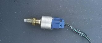
Check valve
This fairly simple part is installed between the amplifier housing and the vacuum hose.
It is easy to check; it should allow air to pass through when blowing in one direction and block it in the other. If there is the slightest doubt, this simplest part must be replaced.
Hoses
The simplest case may be the loss of tightness of the vacuum supply hose. It is easy and inexpensive to replace it with a new one; there are no special requirements for it, other than gasoline resistance and suitable dimensions.
The brakes stopped working
In the worst case scenario, the brake booster control valve fails completely, resulting in complete inoperability of the brake system. Fortunately, such an outcome is unlikely. But if suddenly it does occur, carefully stop the car, tow it home and contact a qualified specialist in the diagnosis and repair of brake systems. Depending on the severity of the case, the matter may be limited to only replacing the valve, but serious repairs of the entire brake system may be required.
The brake booster control valve is an important element of the braking system, ensuring driving safety. That is why the presence of the described symptoms should not be ignored or postponed “for later”. Contact a qualified mechanic who can professionally diagnose and repair your vehicle's brake system.
Failure of the “vacuum seal” is a rather rare failure, but unpleasant - to slow down and stop the car, the driver has to press the brake pedal hard. A sudden failure of the mechanism while driving can provoke an accident - the driver does not have time to change lanes and apply the required force at the right time. To identify signs of critical wear of an element, it is proposed to consider the operating principle of a vacuum brake booster (VBR) and diagnostic methods in a regular garage.
Vacuum brake booster device
Structurally, the vacuum amplifier is a sealed round-shaped housing. It is installed in front of the brake pedal in the engine compartment. The main brake cylinder is located on its body. There is another type of device - a hydraulic vacuum brake booster, which is included in the hydraulic part of the drive.
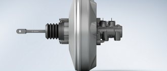
Brake booster circuit diagram
The vacuum brake booster consists of the following elements:
- frame;
- aperture (for two cameras);
- follow-up valve;
- brake pedal pusher;
- brake hydraulic cylinder piston rod;
- return spring.
The body of the device is divided by a diaphragm into two chambers: vacuum and atmospheric. The first is located on the side of the main brake cylinder, the second on the brake pedal side. Through the check valve of the amplifier, the vacuum chamber is connected to a source of vacuum (vacuum), which on cars with a gasoline engine is used by the intake manifold before supplying fuel to the cylinders.
Design and operating algorithm
The first passenger cars produced in the last century were not equipped with “vacuum seals”. To sharply slow down the car in case of emergency braking, the pedal had to be pressed with a force of about 80 kg. The device of the vacuum brake booster installed on modern vehicles makes it possible to reduce the mentioned force to a light press.
To diagnose malfunctions of this unit, you need to know its design and operating principle. The amplifier is a cylindrical metal housing, inside of which the following elements are located:
- a diaphragm pushed by a return spring;
- air valve with two channels - atmospheric and vacuum;
- in the center of the body there is a rod connected at one end to the brake pedal, the other to the main cylinder, and a diaphragm is attached to it;
- vacuum supply pipe from the engine intake manifold connected to the check valve.
In fact, the body of the “vacuum generator” is divided by a membrane into 2 separate chambers. The first is supplied with vacuum from the power unit, while in the second the air pressure is equal to atmospheric pressure. The chambers communicate with each other through the channels of the air valve, which alternately open when the driver presses and releases the pedal.
Design and principle of operation
The VUT is fundamentally simple; it is just a sealed housing, divided into two parts by a flexible partition-membrane.
On one side of the membrane, a vacuum is supplied from the manifold through a flexible reinforced hose, and on the other, the pressure can vary from the same as in the manifold to normal atmospheric pressure.
A rod is connected to the membrane, which applies the force arising from the pressure difference to the GTZ piston. The same place where the driver presses through the pedal with the rod.
If the pedal is not pressed, the interchamber valve is open, they both have no access to the atmosphere, the membrane does not experience unilateral pressure and does not create any force on the rod.
Related article: How to wash and clean a headlight inside and out without disassembling it
As soon as the driver starts braking, the communication between the cameras is interrupted, and outside air begins to flow into the atmosphere.
The pressure difference goes to work, helping the driver's foot. The harder the pressure, the more help. After stopping the braking, the valves return to their original state, and the membrane is retracted into place by a return spring.
The efficiency of amplification depends on the area of the membrane and the depth of vacuum in the vacuum chamber. Therefore, the amplifiers are made of considerable size, they are immediately visible when you open the hood.
Recently, for more precise and engine-independent control, separate vacuum pumps have also been used on gasoline engines.
Operating principle of a vacuum brake booster
Everyone probably knows that the brake system of a modern car is a hydraulic system.
Pressing the pedal creates pressure in the brake fluid, which presses on the pistons, and the pistons, in turn, press the brake pads against the surface of the brake discs. Accordingly, the main force and the force from which it all begins is the force of a person’s foot on the brake pedal. So, thanks to VUT, this effort can be increased several times. The vacuum brake booster consists of two chambers separated by a special membrane. The chamber located closer to the master cylinder is a vacuum chamber and is maintained at low pressure. The chamber facing the brake pedal is called atmospheric. This atmospheric chamber, with the help of a monitoring valve, can be connected either to the chamber where we create a vacuum, or to the immediate environment, that is, to an environment in which the air pressure is a certain and fairly significant value. The VUT also includes a follower valve pusher, which connects directly to the brake pedal, and another important component of the brake booster is the diaphragm return spring. As for the diaphragm, which separates the two chambers, it is equipped with a special nickel in the center, which presses on the piston rod of the master cylinder. When you release the brake pedal, the return spring, true to its name, returns the membrane to its original position.
Now let's describe the operation of the vacuum brake booster, so to speak, in dynamics. The vacuum chamber is connected through a special hose to a device capable of creating a vacuum, or, more simply, a kind of vacuum. Such a device can be either the engine itself, if it is a gasoline engine, or a special vacuum pump. Such pumps are required to be installed in vehicles with diesel power plants. Although, recently VUTs have also begun to be equipped with pumps in gasoline-powered cars. This is necessary for consistently high efficiency of the amplifier at different engine operating modes.
When the car is moving and there is no need to brake, a rarefied area is maintained in both chambers. But, as soon as you press the brake pedal, the valve closes the connection between the chambers and opens access to the atmospheric chamber, atmospheric air at the appropriate pressure. It is this air, plus the force of the person pressing the pedal, that acts on the piston of the master brake cylinder, which ensures the injection of brake fluid into the system. Essentially, a vacuum booster allows us to use atmospheric pressure to increase braking force. As they say: everything ingenious is simple. As for amplifiers that are equipped with vacuum pumps, this solution, in addition to increasing the stability of the VUT, is almost always used for the operation of electronic assistants in driving a car. For example, it is these vacuum pumps that ensure the operation of the ESP system, which is responsible for the car’s stability on turns and corners.
Brake force animation
A modern car is in most cases equipped with two intermediate systems that work as converters of pressure on the brake pedal into the force of pressing the pads against the discs: hydraulic and vacuum. The fluid circuit performs several functions simultaneously.
Its heart is the brake master cylinder (MBC), whose tasks include:
- Creating high braking force on the calipers by multiplying the pressure on the pedals and transferring it to the place of application.
- Reducing frictional wear of moving parts by replacing mechanical components with hydraulic ones.
- Distribution of braking force between the front and rear wheels.
- Providing design flexibility by creating work circuits that are independent from each other. This reduces the likelihood of brake failure.
- Providing technical simplicity compared to mechanical solutions.
- Simplify maintenance.
However, the speeds and masses of vehicles are so high that the hydraulic system's capabilities are insufficient for the force on the cylinder rod to be considered negligible.
Signs and causes of malfunctions
A breakdown of the booster does not lead to a complete failure of the braking system, but much more physical effort is required to slow down the car. The first and main symptom of VUT failure is a sharp decrease in braking efficiency and a feeling of “hardness” in the pedal. Other signs also appear:
- increase in free play (up to about half);
- unstable operation of the power unit, especially at idle;
- the mechanism continues to slow down the car after releasing the pedal - the brakes “stick”.
Note. The amplifier is unable to function normally without supplying vacuum from the motor. Therefore, symptoms of problems should only be checked with the engine running.
The above symptoms of a faulty vacuum brake booster occur for the following reasons:
- air leakage through a gust or loose connection of the vacuum hose;
- wear of the diaphragm leading to loss of tightness;
- failure of the air valve;
- depressurization of the housing;
- decrease in spring elasticity.
The first reason can be easily eliminated in your own garage; the main thing is to check the “vacuum unit” for functionality. Sealing connections or replacing the pipe will not be a big problem. Another issue is when the amplifier breaks down; usually the entire mechanism has to be replaced.
Symptoms and diagnostics
If the VUT malfunctions, the force on the pedals during braking may increase many times over. Driving under these circumstances is unsafe. All symptoms must be immediately diagnosed and the broken unit repaired.
Typically, the vacuum booster is not checked during routine maintenance, so it is important to watch for the following symptoms:
- The pedal became hard. The main indicator that the VUT is worn out or is not working correctly. This may happen gradually or happen suddenly. In addition, the pedal may be positioned higher than usual.
- The braking distance has lengthened. This occurs because it is impossible to obtain the force on the master cylinder rod necessary for the design speed of stopping the vehicle.
- The engine stalls when the brakes are applied. This occurs when the amplifier diaphragm has lost its seal and allows air to leak past the seals. In addition to reduced braking ability, engine stalling can cause major problems on the road.
- The brake system stops working. The failure may be due to a malfunction of the VUT valves.
There is a simple test to evaluate the performance of a servo amplifier. To begin the test, you need to bleed the brakes with the engine off. Five or six clicks will be enough. This will release the vacuum from the tank. Then you should start the engine while lightly pressing the brake pedal. If the amplifier is working properly, the pedal will give a little and then harden. If the VUT is not working correctly, then either nothing will happen, or the pedal will push your foot immediately after starting the engine.
A defective amplifier must be immediately replaced or repaired. If you suspect a malfunction, you cannot continue operating the vehicle. The possibility of self-intervention depends on the specific type of device. Replacing most amplifiers is not difficult for a home mechanic, but it is better to do this procedure in a service station. Working with a repair kit (it may include a diaphragm, valves, rubber seals) clearly requires knowledge and qualifications.
Methods for diagnosing VUT
If one of the above symptoms is detected, you should immediately check the vacuum brake booster for functionality without removing it from the car. Diagnosis is simple:
- Start and warm up the engine.
- Leaving the engine idling, use your hand or pliers to press down the vacuum outlet pipe leading from the manifold. Another option is to disconnect it from the fitting and plug the latter with a wooden wedge.
- Constant behavior of the motor indicates the tightness of the system. The serviceability of the air valve is checked in another way, described below.
- If the speed of the power unit has stabilized or increased, air is leaking through the VUT or supply hose.
Checking the membrane and chamber tightness
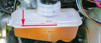
There are several ways to check the serviceability of the vacuum brake booster (VBS), but to ensure that it is 100% operational, it is better to use them all. First of all, press the brake pedal several times with the engine off. When pressed for the first time, the pedal will lower with a fairly insignificant force by about 1/3 of the full stroke, with each subsequent press it should become tighter and the stroke should decrease. If this does not happen, the VUT is most likely faulty, and diagnostics of the vacuum brake booster is required. Next, we will tell you how to check the vacuum brake booster on Kalina.
Thanks for subscribing!
If VUT diagnostics have shown ambiguous results and it is difficult to determine the difference in pedal stroke and pedal stiffness, you can try another method. Press the brake pedal two or three times and start the engine without removing your foot. There are several options for the development of events:
- If the pedal goes deeper a few centimeters, the vacuum brake booster is working properly. You can finally verify this by turning off the engine and not releasing the brake pedal for 30 seconds.
- If the pedal starts to rise, this indicates a leak in the vacuum chamber.
How to check the vacuum brake booster
The braking system of a car is constantly exposed to loads, and in the so-called aggressive style of driving on city streets, these loads increase exorbitantly. In general, influences of this kind are carried out constantly, even if you prefer a loyal level of speed. Therefore, the brake system must be diagnosed with enviable regularity in order to provide the motorist with the maximum degree of safety. Malfunctions in the vacuum amplifier occur, as a rule, due to the loss of condition of the diaphragm located inside this unit. It may burst or become cracked; there is also natural aging of rubber and loss of its qualities. What's the result? The diaphragm stops forming a vacuum. In some cases, the exhaust valve may also fail.
To check the functionality of the vacuum amplifier, you need to resort to the following manipulations:
- We start the engine and let it run a little at idle until the operating temperature level is reached.
- We stop the engine.
- Depress the brake pedal.
- The first movement will be no different from normal when the engine is running. The pedal must be pressed to the limit, in this case the diaphragm is set and a vacuum is formed.
- Release the pedal and press it a second time. If there are any malfunctions in the vacuum booster, then when you press it again you will feel a characteristic short pedal stroke.
- If the reaction of the braking system is the same as the first time, then everything is in order with the amplifier. When the deviations seem insignificant to you, it is worth examining the supply pipes for the presence of microcracks.
In general, each time you press the brake pedal, the engine speed will decrease slightly, however, if the difference becomes significant, it is worth visually diagnosing the hose connecting the amplifier to the power unit. If it has any defects, the collector will become leaky, and accordingly, you won’t have to count on normal mixture formation and the motor will operate unstable. The solution is simple - change the damaged hose.
Removing the vacuum brake booster, checking and replacing the check valve Lada Granta
Tools:
Parts and consumables:
Remove the vacuum brake booster for replacement if it fails.
Removing the vacuum booster
1. Disconnect the wiring harness from the fluid level sensor.
2. Remove the two nuts securing the master cylinder to the brake booster as described in this article.
To prevent air from entering the hydraulic drive of the brake system, do not disconnect the brake pipes from the master cylinder.
3. Carefully bending the brake pipes, remove the main brake cylinder (complete with reservoir) from the vacuum booster studs and move it to the side.
4. Remove the vacuum hose from the booster check valve fitting.
5. In the car interior, under the instrument panel, use a screwdriver to pry the locking bracket of the pin securing the vacuum booster pusher to the brake pedal with a screwdriver.
6. Remove the locking bracket and remove the pin securing the pusher to the pedal.
7. Using a 13 mm socket, unscrew the two nuts securing the amplifier to the pedal assembly bracket.
8. Remove the booster pusher from the bulkhead hole and remove the vacuum booster from the engine compartment.
9. Install the vacuum booster in reverse order.
Before installation, apply sealant to the surface of the amplifier adjacent to the front panel.
Checking and replacing the vacuum booster check valve
Replace the check valve of the vacuum booster or its sealing sleeve without dismantling the booster.
1. After removing the vacuum hose from the valve fitting, remove the valve from the amplifier hole.
2. Place a rubber bulb on the fitting where the check valve is inserted into the vacuum booster and squeeze it. In this case, the air should escape through the check valve.
3. Let go of the pear. If it remains compressed, then the check valve is working properly. Otherwise, replace the check valve in the vacuum booster.
If you don’t have a bulb, you can blow out the check valve with your mouth.
4. Remove the sealing sleeve from the vacuum booster hole. If the bushing is damaged in the form of tears and cracks or if the bushing loses elasticity, it must be replaced.
If the bushing is damaged in the form of tears and cracks or if the bushing loses elasticity, it must be replaced.
The article is missing:
- Photos of parts and consumables
- High-quality photos of repairs
How to change it yourself
Let's look at how to change the VUT using the example of the VAZ 2110, 2111, 2112. The design of the system is quite monotonous, therefore, after watching the video, you can replace the vacuum brake booster of the VAZ 2114 and many other cars.
- Remove the low brake fluid level sensor connector.
- Unscrew the 2 bolts 17 securing the brake cylinder to the VUT body. There is no need to unscrew the lines, just move the cylinder with the tank a little to the side.
- Disconnect the vacuum hose from the check valve. Check the condition of the valve and install it on the new brake booster.
- Unscrew the 4 bolts securing the VUT to the engine shield. The working space in the area of the pedal assembly on the interior side is limited, so an extended socket, extension and ratchet are best suited for unscrewing.
- Disconnect the brake sensor connector.
- Pull out the VUT along with the mounting bracket and the brake pedal.
- Using pliers, remove the locking plate of the brake pedal lever rotation axis.
- Pull out the “finger” that secures the VUT pusher in the lever.
- Unscrew the 2 nuts securing the vacuum body to the bracket.