No further changes were made to the text and diagram. Question 1 - why? Answer: - Price. 350-700 rubles per product for VAZ versus 800-2000 per product for Nexia, if the Chinese slag is Patron, AMD, Mobiletron, HUGO or about 4000 for GM - Reliability. In Nexie-like ones, the switch is shoved into a distributor, where there is a real hell inside. The distributor is screwed to the cylinder head, where the temperature is 80 and above. Electronics does not approve of heating and does ughhh. The size of the heat-conducting plate of the switch is 24*70, but whether the excess heat will be transferred to the distributor body is another question. In addition, the original switch is made like a sandwich: an aluminum plate with ceramics glued onto it, sputtered tracks on the ceramics, and sputtered resistors on the tracks. After heating cycles of all this junk, sooner or later demonic behavior begins.
VAZ switches are assembled on a regular printed circuit board, they have a lot of space, the transistor heatsink is many times larger, and the temperature is lower. — Reachability. VAZ switches are really pasture. They can be bought in the village of Verkhnie Syavki and replacement will come down to unscrewing 1 bolt and plugging the plug. Are there GM switches in the said village? Yes, if only it is a large regional center of the Verkhnesyavkinsky district. Otherwise, the transport company and Exist. For three days you can drink fresh milk and feel the tits of the local female population, laying them out in the cramped interior of Nexia in various interesting positions. — The L497B microcircuit (and its clones) in the VAZ switch is very responsible for pulling the coil. She has nothing else to do. She measures something there, counts, accumulates, charges, knows how to understand that she made a mistake and correct her mistakes in the next flash. Well, in general, she’s smart and an excellent student. She has one drawback: she can only work with Hall. And it starts at a “low” level. Rumors that VAZ switches are dying came to us from the 90s, when they were assembled by cooperatives from stolen goods from factories. It was not always possible to steal good parts. Now the circuitry has been improved. By no means, I do not encourage everyone to screw up the staff schemes. Don't touch the working mechanism. But if she started having problems and died - Wilkommen to the AvtoVAZ-handicraft-club. So, we take the switch 95.3734 (360 rubles), solder the BSZ harness from the classic (100 rubles)! and, using a soldering iron, we assemble Voltran like this hellish crap. Holy water works well as a flux.
Here you can take JPG or SPlan All attention should be paid to the “Ignition Pulse Shaper”. It can be assembled in any way, even on a relay. Pulses from the native switch should get to pin 6 of the VAZ switch in inverted form, and when a “high” level of 3-5V is supplied to the “SHUNT”, pulses from the UO bus from the ECU should get to pin 6 of the VAZ switch, also in inversion. If anyone wants, I will draw 30 variants of such schemes. It was more convenient for me to take a multiplexer. Small transistor VT1 is responsible for inversion. Accordingly, the “Output” direct is not used, unless you include in the circuit switching modules with a high level start, for example from 2110. The multiplexer works like this (see diagram): 2Y0 is connected to 2Z if S1 and S2 are “low”. If you raise S1, 2Y1 will connect to 2Z. Switch. The channel resistance is approximately 45 Ohms, you can make calls. The permissible load in the channel is 10 mA, do not check with a light bulb!
Structurally, I cut out a piece of the board with the said multiplexer, soldered the wiring and the inverter to it, filled it with urethane varnish and epoxy, and hid the resulting module in the wiring harness. Using zip ties and rag tape.
We check the operation of the multiplexer with a tester, from the OUTPUT contact to Pulses or UOS, at low and high levels at the shunt input, respectively. The engine performance does not cause any complaints, starting at -15 with half a turn, at high speeds (150 km/h in 4th gear) it pulls without failures or jerking. If you have any questions, I'm always ready to help. Your Serge. Especially for the radio circle in the village of Verkhnie Syavki, I added a simple version with a relay and the most wasteful parts, which are full of old electronic equipment. Even the most difficult to train pioneers solder. Asked by tema271
Daewoo Nexia 1.5 - unloading the ignition switch
Daewoo Nexia 1.5 - unloading the ignition switch
Is switch offloading a myth or reality? I want to figure it out.
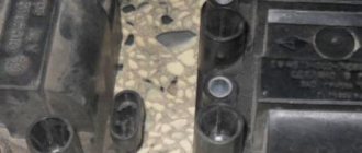
So, an experimental Daewoo Nexia 1.5 with a distributor, inside of which there is an inductive sensor and a switch.
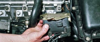
Having been tired of replacing cheap switches that burned out and having read various information on the Internet, the client brought me a VAZ switch and asked me to remake the spark control system in such a way as to relieve the load on the standard circuit using an additional switch from the VAZ.
Indeed, this is discussed on many Opel and Daewoo Nexia forums and very simple connection diagrams are provided. I haven’t tried to redo it, but looking at the proposed diagrams, I see that the engine won’t even be able to start. Are the proposed modification options workable? Let's speculate.
Here is the standard diagram for Daewoo Nexia.
Ramzes4, thank you for your solidarity.
Although in many topics, for example, here on the Opel Kadett C16NZ, the author states: “I connected it according to the diagram (attached) - crap, and off we go...”. However, looking at the oscillograms in the screenshot, you can see that there is no signal at all on Pin *E* (highlighted in purple) at the moment of starter cranking. What then is his statement “shut up and let’s go”? Push the car again until the ECU sees the idle speed and sends a signal to pin *E*
I’ll finish the topic with an analysis of possible connections so that everything is in one place.
1. Connecting the reference signal (green *C*) to the VAZ switch. We get a system without ignition timing control. The respected Shamil Zagidovich described it very eloquently
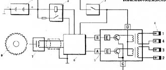
Star964 wrote: The switch consists of two functional parts - a pulse shaper for the ECU, and, in fact, the switch.
For those not fully initiated, a brief description of the operation: - in the start-up mode, +5 V pulses from the driver are sent directly to the switch. That is, the ECU does not participate in the formation of the spark. These same pulses go to the ECU as reference pulses. - when the engine reaches 400 RPM, a voltage of +5 V appears at the “shunt” terminal of the ECU, which is supplied to the switching circuit in the switch. The switching circuit disconnects the driver pulses from the power transistor and connects control pulses coming from the ECU to it. Thus, after 400 RPM, the ECU begins to control the SPD.
I’ll say right away that I’m an absolute beginner in the topic of diagnostics. I need your help. Half a year ago I bought a car from the topic, the mileage was 84,000, now it’s 91,000. From the very beginning there was a problem - it stalls at idle. I went to the service center, they changed 5 pieces of IAC, they charged me 6 thousand rubles. and released, but the problem did not go away. Well, I thought, “it’s not the gods who burn the pots,” I’ll try to figure it out myself, and I’m still figuring it out. I will briefly describe what was done during this time: -replacement of the IAC (5 pieces, at the service, why 5? - you need to ask the mechanic what he did) -replacement of the fuel pump grid -replacement of spark plugs -replacement of the ignition coil -replacement of wires -replacement of the coil in the distributor - checked coolant temperature sensor - good - cleaned the throttle - checked the fuel pump - good - Vince cleaned the ramp, injectors, RTD (there was a lot of dirt, it didn’t fix the problem, the dynamics improved exponentially)
This was all done almost “blindly”, focusing only on the readings on board. computer. About 3 days ago I bought a K-line cable and set up diagnostics on my computer. It turned out that all sensor readings were normal. The only thing that bothered me was the constantly jumping SOP, sometimes the graph shows that either right before it stalls or at that moment the ECU is trying to set the SOP = 89 degrees (according to my ideas about the operation of an internal combustion engine with such a SOP, nothing should work at all). Well, I decided to dig in this direction.
All this time I was driving at speed XX = 1100 without an electrical load, I set them by opening the throttle with a screw, in this mode the car runs stably. In general, having studied this point through the program, I found out that stable operation is observed if the idle speed is “set” by the damper, and you can set it to 800-900, the main thing is not to turn on anything as soon as the idle speed drops to 800, i.e. As I understand it, up to the point where the XX begins to regulate the electronics, everything is a disaster, it stalls and that’s it. After further studying, I realized that the electronics can regulate the idling speed on my car only through the ECU and IAC, well, the only thing left is to exclude the IAC, I found instructions on the Internet on how to disable the ECU adjustment of the IAC, I found it on the forum. I closed A+B in the diagnostic block and the problem went away as if by hand, the car began to regulate the speed only of the IAC, i.e. it turned out to be working (I even inserted my old one and it also turned out to be quite working, I think that the other 4 were also in order, there was no need to go through 5 pieces)
Afterwards I changed the distributor cap and the slider, the problem began to appear less frequently, but did not disappear at all. Well, now a question, or rather several: 1. What happens if you leave A+B closed and drive like that, does this ECU mode affect anything else? 2. Is it possible to programmatically prohibit the ECU from adjusting the idle speed according to the UOZ, without shorting the block (otherwise it is not possible to connect the computer)? 3. What else do you think can be checked in order to understand why the ECU cannot regulate XX SOP?
The ignition system of the Daewoo Nexia depends on the type of engine. On 8-valve engines, non-contact ignition with high-voltage centrifugal distribution is used. The 16-valve engines use a microprocessor ignition system with static high-voltage distribution.
Daewoo Nexia spare parts
Repairing the distributor cap of the Daewoo Nexia, despite the fact that it is considered a complex part and no less capricious, can be carried out on your own.
Therefore, I advise you not to be afraid and try to complete this process, while being sure to follow the given instructions. Emergency Note! For you, Nexia waters and Nexia lovers. If under the hood of your iron friend there is a four-cylinder, eight-valve engine, volume 1.
Distributor daewoo (nexia, matiz) 8 valves: checking the cover and the entire assembly, repair and replacement of the distributor
And it is especially useful for those happy owners of Daewoo Nexia cars. Daewoo Nexia who likes to change high-voltage wires and spark plugs on their own. And he does it very well.
So quickly that he forgets to remember in what order the high-voltage high-voltage wires are connected to the ignition distributor. Common situation? And naturally, in such a situation, the hurry-up starts calling a car mechanic he knows. He talks about the embarrassment that happened to him and asks for help over the phone.
Ignition system of Daewoo Nexia with 8 valve engines
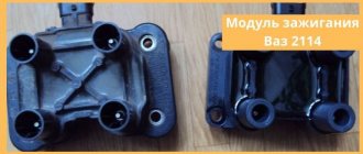
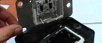
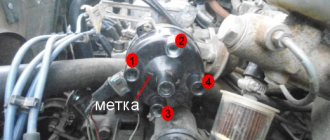
This ignition system, as stated above, is non-contact with a centrifugal distributor. That is, the system must necessarily consist of a distributor, a switch and an ignition coil. The distributor is attached to the cylinder head and connected to the camshaft. When purchasing parts for the distributor, I noticed that almost everywhere they sell a “Hall sensor” for distributors. The same statement is found on many sites on the Internet. But this statement is not true. An inductive sensor is installed in the distributor, that is, a coil on a magnetic circuit in the middle of which a permanent magnet rotates. In this case, an alternating voltage of approximately 3V is induced in the coil. This signal is fed to a switch, which converts the signal and, depending on it, controls the ignition coil. The switch is located inside the distributor.
Air conditioning Daewoo Nexia
Some Nexia cars were equipped with air conditioning. It was included in the most expensive configurations and worked quite reliably with proper maintenance and operation. The main reasons for the failure of the air conditioner, which relate to electrical equipment, were failures of the electromechanical clutch of the compressor drive and breakdowns of the climate control system. Despite the fairly reliable design of the air conditioner itself, there were annoying errors when assembling components, which sometimes led to premature wear of the compressor and evaporator.
Since the operation of the air conditioner is connected to the heating and blowing system, it could not help but respond to frequent failures of the air circulation drive motor. The engine itself cannot be repaired, but before you say goodbye to it, it’s worth checking the circuit right down to the fuses. If there is voltage on the circuit after the fuse, it is quite possible that the contacts in the motor power supply are to blame.
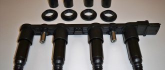
Ignition system of Daewoo Nexia with a 16-valve engine.
Unlike the ignition system, the 8-valve engine does not have a distributor. High voltage is generated by two ignition coils controlled by a two-channel switch, made in the same housing with the coils. This entire structure is called the ignition module. The distribution of high voltage in this case occurs by means of simultaneous supply of voltage in pairs to the cylinders. This system allows you to more accurately adjust the ignition timing depending on many factors.
Electrical diagram of Daewoo Nexia
The Daewoo Nexia electrical circuit diagram of which is presented in this section was not developed yesterday, and this greatly facilitates the repair of the main components of the car. The design of the car as a whole repeats the Opel Cadet of the 80s. Minor changes have been made to decorative elements and optics, and there are also options with a twin-shaft 16-valve engine, which in no way affected the electrical diagram that we posted below.
As you can see, the scheme is simple and to some extent identical to VAZ cars, and those who are familiar with the old Cadet will understand it without any difficulty.
Ignition coils
The ignition coils used with both ignition systems are dry type. On a 16-valve engine, two coils are connected in one housing and have 4 terminals. Two of them are power supply (+ and -), and two are control ones from the ECU. The ignition coil of an 8-valve engine also has four terminals. The two terminals of the coil are connected to each other. One receives the plus from the ignition switch, and from the second the plus is supplied to the switch in the distributor. The remaining two wires suitable for the connectors connect the coil to the tachometer and the switch.
Nexia fuse box
As in all European cars of those times, the Nexia has a fuse block with fork-type fuses. This is much more convenient than the old cartridge elements. Each fuse is responsible for a specific section of the circuit. In the event of an overload or short circuit, the fuse does not allow harm to electrical equipment located in the circuit after it. The basic rule, which cannot be neglected, is that any use of jumpers that short-circuit the contacts tightly, or bugs, is unacceptable. It is also unacceptable to use fuses that do not correspond to the rating. If the fuse has a resistance lower than the rated value, it will blow, and if it is significantly higher, it will burn out the equipment that it was supposed to protect.
For ease of use, fuses have housings of different colors. 10 amp fuses have a red body, 20 amp yellow, 30 amp fuses have a green body. The fuse board is located in the same housing as the relay block, and the entire mounting block is located on the driver's side under the instrument panel.
If there is no spark when starting the engine.
First, let's look at how to check for a spark. Modern ignition systems have a secondary voltage of about 25-32 kV; in early systems the voltage did not exceed 15 kV. The gap during testing should not exceed 10 mm; with a larger gap, the switch may fail. Reasons for the lack of spark on a 16-valve engine, as on most modern injection engines. You can read in detail in the article “Injection engine does not start.”
Troubleshooting on an 8-valve engine is somewhat different and first of all you need to check the presence of power on the positive wire of the distributor and the integrity of the control wire from the distributor to the coil. The most loaded part of the ignition system is the switch and it is also the cause of the malfunction in most cases. It is quite difficult to check it; for this you will need a stand that simulates the operation of the ignition system, or an oscilloscope. Usually it is simply replaced with a known good one. The ignition coil fails extremely rarely, but for some reason, when searching for a lost spark, it is the first to be replaced. Checking the coil is quite simple; you need to measure the resistance of the windings. The measurement value of the primary winding is approximately 0.4-0.6 Ohm, and the secondary winding is about 8.3-8.5 kOhm. When measuring, it is worth taking into account the magnitude of the instrument error. The most common malfunction is a break in the secondary winding, in which case the resistance value will differ significantly from the nominal value.
To check the inductive sensor of the distributor, it is also enough to check its resistance value, which is approximately 400-500 Ohms. A large deviation from the norm indicates a break in the coil and it must be replaced.
The ignition system of the Daewoo Nexia has evolved as the engine has been improved. In fact, the “bottom” of the engine remained unchanged - the crankshaft, cylinder block, crank mechanism and cylinder-piston group. Only the cylinder head has changed; it now has two camshafts. The 8-valve engine had a contactless ignition system with a distributor, switch and ignition coil. The ignition timing was adjusted by turning the distributor in one direction or the other.
The more recent 16-valve engine received a contactless electronic ignition system that does not require manual adjustment.
The design does not have a distributor; the high voltage current is generated by two coils and distributed by a two-channel switch, which in turn is controlled by an electronic engine control unit. Synchronization of ignition timing and injection timing occurs thanks to the precise alignment of the crankshaft and camshafts to the marks. The ignition timing is set by the ECU based on sensor data.
We set the ignition timing on a Nexia with an 8-valve engine
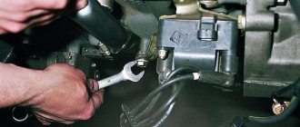
Setting the ignition on an eight-valve engine is quite simple. You can even do without a strobe, using only a standard tool. The operating procedure is as follows:
- We place the car on a level surface and put wheel chocks under the rear wheels.
- Raise the front end with a jack and engage 4th gear.
- Open the hood and look for the mark on the crankshaft pulley and on the timing belt casing.
We combine the marks on the pulley and on the timing belt casing.
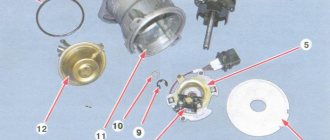
Remove the distributor cover and slider.
Using a 13mm wrench, loosen the distributor mounting bolt and align the protrusions of the magnetic rotor with the protrusions of the stator.
The procedure for connecting high-voltage wires of Daewoo
If we are considering an 8-valve Daewoo Nexia engine with a 1-3-4-2 ignition distributor, then we should remember that the countdown, as a rule, is carried out starting from the contact of the first cylinder in a counterclockwise direction. If you have found it, then now you should determine the desired contact on the distributor cover. To do this, turn the distributor body in your hands and find the arrow-shaped mark. It is this arrow that points to the contact of the distributor cover for the wire of the 1st cylinder.
Read also Magnolia tree photo Sochi
Typical faults
Switchgear of a Daewoo car
If the distributor in a Daewoo Nexia car fails, the symptoms will be as follows:
- The car will jerk while driving.
- The engine may not start at all.
- When the driver presses the gas pedal, detonation may occur - a metallic knock from under the hood.
- The vehicle as a whole picks up speed rather poorly.
- Fuel consumption may increase.
Of course, if such symptoms appear, this does not mean that the problem lies in the distributor. However, if such signs appear, you should first check the spark plugs, the condition of the high-voltage wires that are connected to them, as well as the distributor itself.
If we talk directly about breaker malfunctions, then it is characterized by the following breakdowns:
- burnout of the runner;
- The distributor cover does not work, in particular, the contacts are burnt out;
- Hall sensor failure;
- the bearing element of the sensor is jammed or it is worn out and it’s time to change it;
- presence of damage or cracks on the cover;
- The Hall controller is disconnected or its contact with the wiring is poor;
- Motor fluid got into the distributor (the author of the video is Nail Poroshin).
Ignition of 8 and 16 valves - what is the difference
The ignition system of the Daewoo Nexia has evolved as the engine has been improved. In fact, the “bottom” of the engine remained unchanged - the crankshaft, cylinder block, crank mechanism and cylinder-piston group. Only the cylinder head has changed; it now has two camshafts. The 8-valve engine had a contactless ignition system with a distributor, switch and ignition coil. The ignition timing was adjusted by turning the distributor in one direction or the other.
The more recent 16-valve engine received a contactless electronic ignition system that does not require manual adjustment.
The design does not have a distributor; the high voltage current is generated by two coils and distributed by a two-channel switch, which in turn is controlled by an electronic engine control unit. Synchronization of ignition timing and injection timing occurs thanks to the precise alignment of the crankshaft and camshafts to the marks. The ignition timing is set by the ECU based on sensor data.
We set the ignition timing on a Nexia with an 8-valve engine
Setting the ignition on an eight-valve engine is quite simple. You can even do without a strobe, using only a standard tool. The operating procedure is as follows:
- We place the car on a level surface and put wheel chocks under the rear wheels.
- Raise the front end with a jack and engage 4th gear.
- Open the hood and look for the mark on the crankshaft pulley and on the timing belt casing.
We combine the marks on the pulley and on the timing belt casing.
Remove the distributor cover and slider.
Using a 13mm wrench, loosen the distributor mounting bolt and align the protrusions of the magnetic rotor with the protrusions of the stator.
Ignition system
The contactless ignition system of the Daewoo Nexia works stably and there are no outright complaints about it. In the event that all elements are serviced and checked for mechanical integrity in a timely manner. First of all, this applies to highly loaded devices:
- ignition distributor;
- coils;
- high voltage circuit;
- electronic control unit.
Since 2008, an ECU without feedback has been installed on the car, so its operation has become more stable. In addition to all other corrective functions, the ECU also controls the operation of the ignition system. The control unit adjusts the operation of the system based on the following data:
- crankshaft rotation speed;
- throttle opening angle;
- data from the catalytic converter oxygen sensor;
- temperature and pressure of incoming air.
The ignition system must quickly respond to ECU signals and make adjustments to the advance angle. In case of any abnormal readings, the system informs the driver about the need for maintenance or repair.
Thus, any faults in the electrical equipment of the Daewoo Nexia can be localized, and the diagram posted on the page will help with this. Control the on-board voltage, and have a good trip!
Source
Removing and installing ignition coils for F16D3 and A15SMS Daewoo Nexia N150 engines
Tools:
- Open-end wrench 10 mm
- Ratchet wrench
- Extension
- Head 10 mm
- Medium Phillips screwdriver (for F16D3 engine)
Parts and consumables:
- Ignition module 96453420 (for F16D3 engine)
- Ignition coil 96253555 (for A15SMS engine)
Note:
Remove ignition coils for replacement and when repairing the cylinder head.
Removing and installing the ignition coil of the F16D3 engine
Note:
On the F16D3 engine, you can remove each of the two coils separately (for example, when replacing a faulty coil) or both coils simultaneously (for example, when repairing a cylinder head). Simultaneous removal of both coils is shown.
1. Disconnect the wire from the negative terminals of the battery.
2. While pressing the block latch (gray) of the engine management system wiring harness, disconnect the wiring harness block from the ignition coil connector of the 1st and 4th cylinders.
3. Similarly, disconnect the block (black) of the wiring harness from the ignition coil connector of the 2nd and 3rd cylinders.
4. Remove the ends of the high-voltage wires from the ignition coil terminal.
5. Using a 10 mm socket, unscrew the three nuts securing the ignition coil bracket to the cylinder head bracket.
6. Remove the bracket with the ignition coils from the cylinder head bracket studs.
7. Using a Phillips screwdriver, unscrew the two screws securing the ignition coil to the bracket and remove the coil.
Removed ignition coil from F16D3 engine
8. Remove the other ignition coil in the same way.
9. Install the ignition coils in reverse order.
Note:
Connect the ends of the high-voltage wires to the coils in accordance with the cylinder numbers marked on the wires and coil housings next to their terminals.
Removing and installing the ignition coil of the A15SMS engine
1. To remove the ignition coil on the A15SMS engine, release the lock of the engine management system wiring harness block and disconnect the wiring harness block from the ignition coil.
2. Remove the ends of the high-voltage wires from the ignition coil terminals.
3. Using a 10 mm socket with an extension, unscrew the three nuts securing the ignition coil to the bracket and remove the coil.
4. Install the ignition coil in reverse order.
Note:
Connect the ends of the high-voltage wires to the coil in accordance with the cylinder numbers marked on the coil body next to its terminals.
The article is missing:
- Photo of the instrument
Source:
Design Features
The one and a half liter single-shaft in-line petrol engine G15MF was created before the advent of Euro-2 standards, so the design feature is an extremely simple exhaust tract design without a catalyst and CO probe. The remaining nuances of the internal combustion engine are:
- modernization of the injection system - injection here is distributed, but simultaneous, regulated by a potentiometer, as on domestic Ladas;
- modification of the combustion chambers - these engines have a smaller cylinder diameter compared to the prototype, and a dome-shaped chamber, partially extended into the piston;
- according to the manufacturer, oil consumption is within 300 g/1000 km, and gasoline consumption is 8.8 l/100 km in the combined cycle;
- flat tooth timing belt from the leading brand Geitz with a service life of 200,000 km, although the safety of the valves is already ensured here, they cannot meet the pistons.
Timing belt G15MF
The gas distribution system is made according to the SOHC scheme with one camshaft. Compared to the sample, the volumes of the combustion chambers are reduced; power will be increased only in the next series of Daewoo engines - A15MF.
To increase the resource, the attachment is driven by a separate belt, the condition of which is recommended to be monitored every 20 thousand km, and changed after 50 thousand.
After the introduction of Euro-3 and even Euro-4 regulations, Daewoo management continued to install these obsolete power drives on Nexia and Espero until 2008. Compactly located attachments do not interfere with major repairs, including on your own.
Connection diagram for high-voltage wires Daewoo Lanos, Daewoo Nexia (Daewoo Lanos, Daewoo Nexia)
There is a contact in the middle of the distributor cap to which we connect the central wire that comes from the ignition coil.
So, the main thing is not to forget the main rule for installing high-voltage wires on Daewoo, Daewoo Lanos, Daewoo Nexia (Daewoo Lanos, Daewoo Nexia) - the cylinders are counted from the timing belt from left to right.
I think connecting high-voltage wires with your own hands is not a problem, the main thing is to follow all the above recommendations. If you have a different car, you should find the order of operation of the cylinders in the car's operating manual or on the Internet as a last resort and replace the high-voltage wires according to the same principle. In order to avoid the difficulties of finding information about replacing high-voltage wires in the future, you can make small marks with a marker on the distributor cover.
Let me remind you once again:
The order of connecting high-voltage wires of Daewoo Nexia (Daewoo Nexia) 1-3-4-2
The order of connecting high-voltage wires of Daewoo Lanos (Daewoo Lanos) is 1-3-4-2.
For the convenience of Daewoo Lanos car owners, we have collected all the Daewoo Lanos electrical circuits:
Characteristics
| Engine | 8 valves |
| Analogue | NP1332 |
| vendor code | PECE06 |
| Manufacturer | PARTS-MALL |
| Country of Origin | Korea |
High-voltage wires (spark plug) Daewoo Nexia SOHC 8-valves N100 up to 2008 (distributor)
Manufacturer - Parts Mall (Korea)
You can buy high-voltage wires for the Daewoo Nexia 8 cl until 2008 with delivery to the address you need in Moscow or other cities of Russia, or you can pick up your order from our store.
→ Product description → Go to Google images → Additional information on the supplier → Product delivery statistics
You can buy high-voltage wires Daewoo Nexia SOHC 8-valves until 2008 (distributor) PARTS-MALL (article PECE06) with delivery to the address you need in Moscow or other cities of Russia, you can also pick up your order from our store.
Read also: Volcano cake recipe with step-by-step video
INFORMATION FOR BUYERS
Prices are valid for the online store only and may differ from prices in our retail store. Be careful when picking up! Without ordering on the website, product prices will be retail prices!
Problems with power windows
The build quality of the Daewoo Nexia, unfortunately, very much depends on the factory at which the car was assembled. Most often, problems with window regulators arise on Russian-assembled Daewoos, and the components supplied to both Uzbekistan and Poland are, apparently, exactly the same. However, if problems arise with the window regulators, you need to make sure that the problem is in the electrical part. If everything is fine with the mechanics, then you should check the fuse in the mounting block.
If everything is in order with it, then most likely it is in the lift control unit. The main unit is located in the driver's door armrest. The most likely failure is failure of the control keys or lack of contact in the control unit. The fact is that the door is constantly subject to vibration, so due to poor quality assembly, the contacts may simply come off.
Create an account or log in to comment
How I adjusted the ignition Everything is correct. I hear a rattling ringing sound during acceleration when the engine is running tight - is that them?
And where should the sound come from? This is neither bad nor good. Remove the distributor cap and slider.
Remove the distributor cover and slider. We see a slot on the shaft, which should be directed either up or down.
Using a 13mm wrench, loosen the distributor fixing bolts. Using a 13mm wrench, loosen the distributor mounting bolt and align the protrusions of the magnetic rotor with the protrusions of the stator.
Now all that remains is to combine the protrusions of the magnetic rotor with the positive stationary ebbs. Theoretically, the advance angle is set, but, making adjustments for gasoline, we turn the distributor another mm clockwise. Install the slider and cover.
Conclusion We check the correct installation while running.
We set the ignition on the injection Daewoo Nexia: the difference between 8 and 16 valves
The operation of the engine in any mode almost completely depends on the accuracy of setting the ignition timing in the Daewoo Nexia engine. If you make a mistake by a millimeter, the engine will not be able to idle correctly, start normally and consume fuel economically. Setting the ignition on the Nexia is quite simple, the main thing is to strictly follow the instructions.
Create an account or log in to comment
How I adjusted the ignition Everything is correct. I hear a rattling ringing sound during acceleration when the engine is running tight - is that them?
And where should the sound come from? This is neither bad nor good. Remove the distributor cap and slider.
Remove the distributor cover and slider. We see a slot on the shaft, which should be directed either up or down.
Using a 13mm wrench, loosen the distributor fixing bolts. Using a 13mm wrench, loosen the distributor mounting bolt and align the protrusions of the magnetic rotor with the protrusions of the stator.
Now all that remains is to combine the protrusions of the magnetic rotor with the positive stationary ebbs. Theoretically, the advance angle is set, but, making adjustments for gasoline, we turn the distributor another mm clockwise. Install the slider and cover.
Conclusion We check the correct installation while running.
How to check the device for serviceability?
The distributor diagnostic procedure is carried out as follows:
- First, you need to look at the engine in the dark to see if there are sparks in the distributor area. If there is, then this indicates a violation of the insulation. Remember to always keep the lid dry.
- Also diagnose the integrity of the wiring - whether the contacts are intact or not. The terminals themselves on the cover must not be removed.
- Remove the cover and diagnose the integrity of the slider. After removal, look at the inside of the cover to see if the contacts are intact.
- Try shaking the slider - any gaps are eliminated. If there is play, there will be an unstable gap in the contacts.
- Diagnose the wear and gap in the contacts - it should be no more than 2 mm, the less the gap, the better. If the contacts are burnt, they must be cleaned.
- Then connect the lamp to the side terminal of the distributor and turn on the ignition. Try turning the engine manually - at this time the lamp should blink and go out at regular intervals. If this does not happen, then most likely there is a short circuit in the system, as a rule, this is due to the fact that the moving part touches the housing itself (the author of the video about diagnosing the distributor cap at home is Auto Electrics HF).