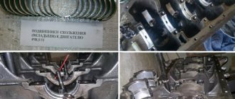
The procedure for tightening the cylinder head on a VAZ 2110 during repair
It’s probably no secret to anyone that our cars need servicing much more often than foreign cars. This applies primarily to VAZ cars of all generations. As a rule, these cars are purchased by people with average incomes and constant servicing of the car at a service station is an unaffordable luxury. To save money, you need to learn how to do some work yourself. For example, it is necessary to be able to correctly tighten the bolts of the cylinder head of the VAZ 2110 8 valves, the tightening order of which is strictly regulated.
This work is difficult at first glance, but in reality, car enthusiasts, faced with it for the first time, cope quite successfully, thereby saving their time and money. It is worth knowing that the tightening of bolts on an 8 valve and 16 valve engine has some similarities and some quite important differences. For example, if their tightening torque is the same, then the pattern according to which this process occurs, that is, the order, is completely different. This must not be forgotten, otherwise all the work will be ruined by simply not following the order of tightening the bolts. If tightened incorrectly, it is quite possible that the gasket will be skewed or squeezed and, as a result, depressurize the structure and loss of performance characteristics of the VAZ 2110 cylinder head.
Lada 110
Bolt tightening conditions
When installing the cylinder head, it is important to comply with the tightening technology, which includes a number of criteria:
- Tightening order;
- An effort;
- Condition of fasteners (for example, studs with nuts);
Each engine has its own tightening order, which must be followed to ensure uniform tightening of the head to the block and to prevent the occurrence of stress on any surface areas. For example, on a VAZ 2105 it looks like this.
Force is another important factor for the correct fastening of this engine element. Attracting the plate is carried out in several approaches (their number differs on different motors), each of which is performed with its own force.
The cylinder head fasteners are tightened with quite a lot of force, which leads to them being pulled out. Therefore, on many engines, bolts cannot be reused; they must be replaced. But there are also motors for which replacement of fasteners is not necessary and their re-installation is possible.
All information regarding the cylinder head tightening technology is indicated in the technical specifications. documentation for the car, it is also often indicated on the packaging of head gaskets and fasteners.
In what cases is it necessary to tighten the block?
It becomes necessary to tighten the bolts if the cylinder head was removed to change the gasket or repair some components. Also, some car owners recommend tightening after a certain period of operation of the car or after a certain mileage of the VAZ 2110. It is important to know that before installing the head it is always recommended to install a new gasket.
Reinstalling an old one, even if it is in good condition, may not give the desired result. A new gasket is inexpensive and for VAZ 2110 cars they are sold in almost all car stores. You also need to know that the bolts that secure the cylinder head wear out over time and, under constant stress, can even stretch to some extent. Re-installation of bolts is permissible, but only when their length is no more than 9.5 centimeters.
The length should not exceed 9.5 centimeters
They are also free from damage and rust. But since they are inexpensive, it is better not to skimp and purchase a new set of bolts.
Features of the work performed using the example of some cars
To prove the proposition that each power plant has its own characteristics of tightening the cylinder head, let’s consider the nuances of performing work on specific models.
VAZ-2112 16 valves
A number of modifications of the VAZ-2112 were equipped with two types of 16-valve power plants (factory indexes - 21120 and 21124). These two motors, despite some design features, have identical head tightening technology.
These units use 93mm long tension bolts. In this case, reuse of fasteners is allowed, but under one condition - if their length does not exceed 95 mm (if it is longer, they should be replaced). 10 bolts are used to secure the head.
Tightening is carried out in three approaches:
- The bolts are tightened according to the order with a force of 2 kg/m;
- Turning 90 degrees;
- Repeated tightening to 90 degrees.
The drawing diagram is shown below.
Between the 2nd and 3rd approaches you need to take a 20-minute break.
Since these engines use tensile bolts, additional tightening is not required during vehicle operation.
VAZ-2107
On the VAZ-2107, all installed modifications of power units are 8-valve.
The block head is attached to them with 11 bolts, 10 of which are main, and 1 is an auxiliary side bolt (installed in the side protrusion).
On this car, tightening fasteners is also performed in three approaches:
- 10 main bolts are tightened in order with a force of 3.5-4.0 kg/m;
- The same bolts reach with a torque of 11.5-12.0 kg/m;
- The auxiliary is tightened with a force of 3.5-4.0 kg/m.
Additional tightening of the cylinder head is not required when operating the VAZ-2107.
"Samara", 10th family, Priora
On models of the Samara family (2108-21099), as well as VAZ 2110-2112 with 8-valve units, tightening is already performed in 4 approaches:
- Tightening with a force of 2.0 kg/m;
- Reaching with a moment of 7.5-8.5 kg/m;
- Turn 90 degrees;
- Repeated rotation by 90 degrees.
The break between points 3 and 4 is 20 minutes.
As for the VAZ of the “tenth” family, which are equipped with 16-valve engines, their tightening technology is the same as that of the VAZ-2112 (described above).
The same applies to the Lada Priora; on 8-valve units, a method with 4 approaches is used (VAZ 2108-21099), and on 16-valve units, 3 approaches are used (VAZ 2112 with a 16-valve engine).
"Volga"
On ZMZ-406 engines installed on the Volga, according to the automaker’s technical documentation, tightening the engine block head bolts is carried out in two approaches:
- With a force of 4.0-6.0 kg/m;
- With a moment of 13.0-14.5 kg/m.
But many car owners of this car note that this technology does not allow the cylinder head to be properly tightened, so they use techniques with a large number of approaches.
A common method is the cross method, performed in 4 stages and with the following efforts:
Subsequent tightening of the bolts is not required when operating on this engine.
Tightening process and diagram (on an 8-valve car)
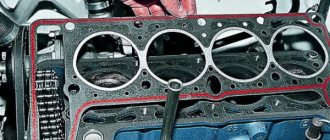
As we have already said, the procedure for tightening the cylinder head bolts on an 8-valve and a sixteen-valve unit is very similar. The tightening torque is the same in both cases, but the bolts are unscrewed and then tightened according to a completely different pattern. It is important to thoroughly clean the contacting surfaces before installing a new or old VAZ 2110 cylinder head. It is highly undesirable to do this with sandpaper, a file or other hard objects that can damage these surfaces.
Rough cleaning of the surface can lead to depressurization of the cylinder block system with ensuing dangerous consequences. For this purpose, special liquids are sold in the store. They are applied to a surface that may have remnants of an old gasket or other contaminants and are left to dry for some time. After some time, they are carefully removed and the surface remains perfectly clean.
Required Tools
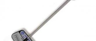
- torque wrench;
Key for tightening to the required torque
- rod compass;
- surface treatment liquid;
- knob;
- new gasket;
Tighten the engine bolts correctly
In the table below we have indicated the tightening torques for all threaded connections on the VAZ-2112 engine.
Tightening torque of threaded connections (table)
Measuring tool
Despite the fact that performing work according to the tightening rules requires a special approach, such a procedure will not take a lot of time.
The only thing required to perform such work is a torque wrench.
This wrench is used to measure the tightening torque.
You can get such a tool in any store, but its price is often steep and can sometimes reach 2,000 rubles.
see also
The cylinder head gasket has smaller holes for coolant
0 2 1k
The cylinder head gasket on 2112 was broken
- 0 1 809
What is needed to replace the cylinder head gasket on a 2112?
- 0 1 1k
I unscrewed the cylinder head bolts, do I need to change the gasket?
- 0 2 1k
How to eliminate craters on the block and cylinder head?
- 0 1 0
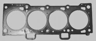
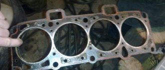
The cylinder head gasket is a perforated sheet made of iron and asbestos or aluminum paronite with edging on the sides and holes for cylinder chambers and connecting bolts. The main task of the cylinder head gasket is to seal the connection between the planes of the cylinder block. In addition, the gasket maintains the required internal oil pressure in the engine system and also prevents mixing of coolant and engine oil.
Operating procedure
- Disconnect the wire from the “–” terminal of the battery.
- Set the piston of the 1st cylinder to the TDC position of the compression stroke
- Drain the coolant.
- On fuel-injected models, reduce fuel system pressure if work is being done immediately after driving.
- Disconnect the muffler exhaust pipe from the exhaust manifold
- Remove the thermostat
- Unscrew nut 1 securing the bracket to the water pump supply pipe and loosen nut 2 securing the bracket to the exhaust manifold.
- Move the bracket to the side.
- Disconnect the block with wires from the oil level sensor in the engine crankcase.
- In addition, on the engine mod. 2111 unscrew or loosen the nut securing the support bracket 1, unscrew the bolt securing the support bracket 2 and...
- ...disconnect the block (white) with wires from the crankshaft position sensor by pressing the plastic latch.
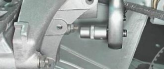
- Remove the camshaft drive belt from its timing pulley, tension roller, water pump timing pulley, move it to the side and remove the tension roller.
- Secure the camshaft timing pulley from turning by inserting a screwdriver (shown by the arrow) into its hole and resting it against the pin, unscrew the pulley mounting bolt and remove it along with the washer.
- Using two screwdrivers, remove the pulley from the camshaft. Do not damage the camshaft oil seal.
- Unscrew the nuts securing the rear timing belt cover. Let's dismantle it.
- Next, loosen all the clamps on the pipes using a Phillips screwdriver connected to the cylinder head exhaust pipe. We disconnect them.
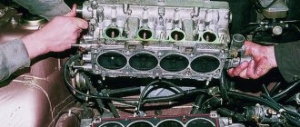
- Using a 10mm hexagon, unscrew the bolts (studs) securing the cylinder head to the block itself.
- Be careful as the bolts are removed along with the washers.
- Now you can dismantle the head along with the old gasket.
- Removed bolts should be checked for tension. Their length should not be more than 135.5 mm. Otherwise, replace them with new ones. Before installation, it is recommended to lubricate them with appropriate lubricant or engine oil (working will do).
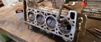
- The surfaces must be thoroughly cleaned of the old gasket and its adhering parts. The contact between the head and the cylinder block must be smooth, without defects, otherwise the cylinder head must be ground on a machine. Check all holes to ensure there is no oil or coolant in them.
- The new gasket being installed must be dry and clean. When installing, pay attention to the oil hole, which should be located between cylinders 3 and 4.
- In the installed cylinder head, the valves of the first cylinder must be in the closed position.
- The bolts should be tightened with a torque wrench strictly in the sequence indicated in the photo according to the following scheme: The first pass is 20 Nm, the second is 70-85 Nm, the third is turned by 90°, the fourth by another 90º.
- Then assembly occurs in reverse order. The camshafts and crankshaft should be kept stationary until the timing belt is installed. The camshaft pulley is installed with the protruding part of the hub facing the engine.
- Finally, it is necessary to adjust the timing belt tension and valve clearances.
We invite you to watch a video about removing the cylinder head.
1200 rub. for the photo report
We pay for photo reports on car repairs. Earnings from 10,000 rubles/month.
Write:
The cylinder head gasket is a perforated sheet made of iron and asbestos or aluminum paronite with edging on the sides and holes for cylinder chambers and connecting bolts. The main task of the cylinder head gasket is to seal the connection between the planes of the cylinder block. In addition, the gasket maintains the required internal oil pressure in the engine system and also prevents mixing of coolant and engine oil.
Signs of failure of the cylinder head gasket of a VAZ 2110
There are no specific warranty periods for the use of a cylinder head gasket. Its durability is influenced by such factors as: the degree of operation of the engine, its model, driving style and other reasons. However, there are several symptoms by which you can determine that the gasket has failed:
- at the junction of the block and the head there are leaks of engine oil or coolant ;
- using an oil dipstick, foreign light impurities or foam-like emulsion , which occurs when antifreeze penetrates through the connection with the cylinder head;
- the color of the exhaust changes to bluish-white, which indicates water entering the combustion chamber of the cylinder block;
- presence of oil stains in the coolant reservoir;
- The engine temperature rises due to the breakthrough of hot gases into the cooling system, which immediately heat the coolant.
Tips for replacing the cylinder head gasket
Removal and installation of the cylinder head gasket is carried out with the crankshaft set to TDC. It is also necessary to ensure that both valves of the 1st cylinder are closed.
It must be remembered that the cylinder head gasket must be changed after each removal of the engine head, even if this is not due to its unsuitability.
The procedure for replacing the cylinder head gasket on a VAZ 2110 on a 16-valve engine is generally similar to how to change the cylinder head gasket on an 8-valve engine, but has several nuances :
- The receiver must be dismantled.
- When removing timing belt pulleys, a mark is placed on two pulleys and two pulleys are removed.
- The fuel rail is removed.
- The order and tightening torques are carried out in accordance with the requirements for a 16-valve engine.
When is it necessary to remove the cylinder head?
On cars that came off the assembly line of the Volzhsky Automobile Plant, regardless of how many valves the power unit has and which drive (rear or front) is used, tightening is carried out after disassembling the cylinder block. As noted above, usually dismantling the head is needed to replace the gasket, the service life of which is 60,000 or a maximum of 80,000 kilometers. The deterioration of the sealing element seriously affects the operation of the engine, and therefore it is better not to use the machine until it is repaired.
What is needed to replace the cylinder head gasket of a VAZ 2110 (8 valves)
Required tools :
- ratchet with 10mm socket heads; “at 13”, “at 17”, “at 19”;
- wrench with Torx bit;
- screwdriver;
- torque wrench;
- wrench for removing spark plugs.
Suitable accessories :
- the TRIALLI gasket set has article number GZ1017022, its price is 500 rubles ;
- The VICTOR REINZ cylinder head gasket has article number 613666000, its price is 280 rubles ;
- The original VAZ (VATI) cylinder head gasket has article number 21083100302020, its price is 140 rubles .
The price of gaskets is relevant for the summer of 2017 for Moscow and the region.
Set the piston of cylinder 1 to the TDC position on the compression stroke. We fix the camshaft toothed pulley from turning with a clamp. We unscrew the candles.
A) Using a 10mm wrench, unscrew the two nuts securing the throttle drive cable bracket to the receiver and remove it. B) Remove the crankcase ventilation hoses and the supply hose from the valve cover fittings. C) Using a 10mm wrench, unscrew the two nuts securing the valve cover and remove it.
Using a 10mm wrench, unscrew the bolts of the front timing cover: two on the side and one in the center. Remove the timing cover.
We check the coincidence of the mark on the camshaft timing pulley with the installation antenna on the rear cover of the timing drive. Using a 17 key, unscrew the pulley.
Using a 10mm wrench, unscrew the nut securing the protective casing and bend the casing.
We see that the timing belt also requires replacement.
Disconnect the oil level pressure sensor connector.
Using a 10mm wrench, unscrew two nuts and one bolt securing the plug. Evenly, using a 13mm wrench, unscrew the six nuts securing the rear camshaft bearing housing. Remove the rear camshaft bearing housings from the studs.
Then, also evenly and using a 13mm wrench, unscrew the four nuts securing the front camshaft bearing housing and remove it.
Unscrew the four nuts securing the muffler to the exhaust manifold.
Using an E14 Torx head, unscrew the 10 bolts on the cylinder block and remove the block.
Removing the cylinder head - key points
Now it’s the cylinder head’s turn. First, use a socket wrench of the appropriate size to remove its casing. Place the removed nuts and washers so as not to lose them. In addition, to gain access to the head, the timing chain must also be disconnected. Carefully loosen the tensioner and remove it completely after unscrewing the gear. To prevent the chain from slipping off the last one, it is tied together with any soft wire.
Next, the camshaft is disconnected - it is attached in nine places. If the tightening is too strong, then use WD-40 again.
After dismantling the shaft, remove the fuel supply hose and exhaust manifold from the cylinder head. We will not dwell on this point - everything is simple here.
Now unscrew the head bolts - there are 11 of them (one is in the lower left corner on a separate “ear”). If the cover is stuck to the gasket, carefully pry it off using a long screwdriver as a lever (rest it on the pipe leading to the manifold).
Replacement intervals for the cylinder head gasket on the VAZ-2110
The most important thing that interests owners is the replacement interval for this part.
It is very difficult to say how long a particular gasket will last.
- Manufacturer of the part.
- The quality of the material from which the gasket is made.
- The conditions under which these parts were stored.
Since the gasket is made of rubber, storage conditions directly affect its service life. For example, a part purchased at the market, which was stored for a long time in a damp and unheated container, will be worse than the same spare part purchased in a store.
The main function is to ensure maximum sealing of the cylinder block with the cylinder head. If you do not monitor the condition, the engine life will be significantly reduced.
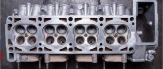
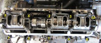
Procedure for installation and dismantling
The cylinder block is the basis for mounting the head, which is held on by 10 screws. Unscrewing is carried out with a special socket wrench - “ten”.
The photo shows the correct folding order:
- Top right corner.
- Bottom right corner.
- Top left corner.
- Bottom left corner.
- Top second from left.
- Top second from the right.
- Second bottom from the right.
- Second bottom from the left.
- Top in the middle.
- Bottom in the middle.
Signs of a broken gasket
You can find out that the seal of the connection is broken for the following reasons:
- White vapor appears in the exhaust gases.
- You may notice oil stains in the antifreeze.
- Leak in cylinder head connections.
- There is a large amount of oil in the pan.
- You may notice foam around the filler cap.
Although it seems that it is very difficult to notice the vapors in antifreeze, this can be done by placing a bag over the neck of the open expansion tank. If there are gases in the antifreeze, the bag will inflate.
Articles
Before you start replacing the gasket, you should purchase this gasket. Although any car store will select a suitable spare part for you, it is better to know its part number. The most suitable gaskets for the VAZ-2110 are:
- The original VATI gasket, which has the article number 21083100302020.
- Part VICTOR REINZ. This item is of higher quality than the original. Its article number is 613666000.
- TRIALLI gaskets, which have the article number GZ.
It’s better to immediately buy a better quality spare part than to bother with disassembly again later.
Tools
Although this part can be replaced right near the house, it is better to carry out all replacement operations in the inspection hole. To replace you will need the following tools:
- Set of sockets for ratchet. Heads must be from 10 to 19;
- Torx key;
- Several screwdrivers;
- Candle key;
- Torque wrench.
A special liquid, WD-40, will also come in handy, which will help when unscrewing soured bolts. As the practice of such repairs shows, during disassembly it is often necessary to use other tools, so having them will never hurt.
Setting the screw tightening torque
It is very important to follow the instructions for accurate tightening. It must be carried out using a torque wrench in order to keep track of the tightening torque of the VAZ 2109 cylinder head. If the torque does not vary when turning the bolt, then this is normal, since the fastening can stretch. As the torque increases, it is necessary to achieve movement of the screw, since the amount of stretch in this case is small.
Article on how to install: Timing belt Lada Priora
Bolts have their own service life, their structure can be subject to destruction, since they are subject to heavy loads and often with temperature fluctuations.
Rules for tightening screws:
- You must strictly follow the instructions in the car manual.
- Work only with a torque wrench and not with other tools.
- Bolts for tightening must be intact and in good condition. They must match the engine installed on the VAZ 2109.
- Before tightening, make sure that the holders are in good working order.
At the beginning of the process, the current condition of the bolts is checked. Proper use of the vehicle minimizes the need for a cylinder head tightening.
Replacement procedure
The replacement process occurs as follows:
- First you need to disconnect the battery; to do this, remove the negative terminal.
- You need to disconnect the exhaust pipe from the muffler.
- We dismantle the carburetor.
- Next, you need to disconnect all the sensor terminals, and all the wires are disconnected from the spark plugs.
- The next step is to disconnect the vacuum booster from the intake manifold.
- The distributor sensor is disconnected.
- Disconnect the high-voltage wires.
- Unscrew the nuts and remove the sensor.
- The fuel pump and the housing of auxiliary devices are dismantled.
The roller and timing belt are removed.
- The pulley is dismantled, after which you need to remove the timing cover.
- Disconnect the hoses and unscrew the cover nuts.
After this, all that remains is to unscrew the bolts and remove the block head. After removing the old gasket, you need to carefully inspect the contact surfaces of the head and cylinder block. There should be no dirt or residue from the old gasket on them. All obvious signs of contamination must be eliminated.
Tightening torques for threaded connections
| Detail | Thread | Tightening torque, N m (kgf m) |
| Engine | ||
| Cylinder head bolt (cylinder head bolt) | M12x1.25 | see note 2 at bottom of page |
| Nut of the stud securing the intake pipe and exhaust manifold | M8 | 20,87–25,77 (2,13–2,63) |
| Tension roller nut | M10×1.25 | 33,23–41,16 (3,4–4,2) |
| Camshaft bearing housing stud nut | M8 | 18,38–22,64 (1,87–2,31) |
| Camshaft pulley bolt | M10 | 67,42–83,3 (6,88–8,5) |
| Accessory housing mounting bolt | M6 | 6,66–8,23 (0,68–0,84) |
| Nut of the stud securing the exhaust pipe of the cooling jacket | M8 | 15,97–22,64 (1,63–2,31) |
| Main bearing cap bolt | M10x1.25 | 68,31–84,38 (6,97–8,61) |
| Oil sump bolt | M6 | 5,15–8,23 (0,52–0,84) |
| Connecting rod cap bolt nut | M9x1 | 43,32–53,51 (4,42–5,46) |
| Flywheel bolt | M10x1.25 | 60,96–87,42 (6,22–8,92) |
| Coolant pump mounting bolt | M6 | 7,64–8,01 (0,78–0,82) |
| Crankshaft pulley bolt | M12x1.25 | 97,9–108,78 (9,9–11,1) |
| Coolant pump inlet pipe mounting bolt | M6 | 4,17–5,15 (0,425–0,525) |
| Muffler exhaust pipe fastening nut | M8×1.25 | 20,87–25,77 (2,13–2,63) |
| Nut securing the flange of the additional muffler | M8×1.25 | 15,97–22,64 (1,63–2,31) |
| Nut securing the clutch cable to the engine bracket | M12x1 | 14,7–19,6 (1,5–2,0) |
| Front engine mount bracket bolt | M10x1.25 | 32,2–51,9 (3,3–5,5) |
| Front engine mount bolt nut | M10 | 41,65–51,45 (4,25–5,25) |
| Nut of the bolt securing the left suspension support of the power unit | M10 | 41,65–51,45 (4,25–5,25) |
| Nut securing the bracket of the left suspension support of the power unit | M10 | 31,85–51,45 (3,25–5,25) |
| Bolt securing the rear suspension support of the power unit | M10x1.25 | 27,44–34 (2,8–3,47) |
| Nut of the power unit rear suspension bracket mounting bolt | M12 | 60,7–98 (6,2–10) |
| Bolt securing the oil receiver to the main bearing cover | M6 | 8,33–10,29 (0,85–1,05) |
| Bolt securing the oil receiver to the pump | M6 | 6,86–8,23 (0,7–0,84) |
| Oil pump mounting bolt | M6 | 8,33–10,29 (0,85–1,05) |
| Oil pump housing bolt | M6 | 7,2–9,2 (0,735–0,94) |
| Oil pump pressure reducing valve plug | M16x1.5 | 45,5–73,5 (4,64–7,5) |
| Oil filter fitting | M20×1.5 | 37,48–87,47 (3,8–8,9) |
| Oil pressure warning light sensor | M14x1.5 | 24–27 (2,45–2,75) |
| Carburetor mounting nut | M8 | 12,8–15,9 (1,3–1,6) |
| Cylinder head cover nut | M6 | 1,96–4,6 (0,2–0,47) |
| Clutch | ||
| Nut securing the clutch housing to the engine block | M12x1.25 | 54,2–87,6 (5,53–8,93) |
| Bolt securing the clutch housing to the engine block | M12x1.25 | 54,2–87,6 (5,53–8,93) |
| Clutch release bearing guide flange bolt | M6 | 3,8–6,2 (0,39–0,63) |
| Bolt securing clutch housing to flywheel | M8 | 19,13–30,9 (1,95–3,15) |
| Nut securing the clutch housing to the gearbox | M8 | 15,7–25,5 (1,6–2,6) |
| Bolt securing the bottom cover to the clutch housing | M6 | 3,8–6,2 (0,4–0,6) |
| Transmission | ||
| Conical screw for fastening the drive rod joint | M8 | 16,3–20,1 (1,66–2,05) |
| Gear selector mounting bolt | M6 | 6,4–10,3 (0,65–1,05) |
| Shift Lever Housing Bolt | M8 | 15,7–25,5 (1,6–2,6) |
| Nut securing the drive rod and torque rod clamp | M8 | 15,7–25,5 (1,6–2,6) |
| Nut of the rear end of the primary and secondary shafts | M20x1.5 | 120,8–149,2 (12,3–15,2) |
| Reversing light switch | M14x1.5 | 28,4–45,3 (2,9–4,6) |
| Bolt securing the forks to the rod | M6 | 11,7–18,6 (1,2–1,9) |
| Differential driven gear bolt | M10x1.25 | 63,5–82,5 (6,5–8,4) |
| Speedometer drive housing fastening nut | M6 | 4,5–7,2 (0,45–0,73) |
| Gear selector shaft mounting bolt | M6 | 11,7–18,6 (1,2–1,9) |
| Nut securing the rear cover to the gearbox housing | M8 | 15,7–25,5 (1,6–2,6) |
| Reverse fork clamp plug | M16×1.5 | 28,4–45,3 (2,89–4,6) |
| Conical screw for fastening the gear selector rod lever | M8 | 28,4–35 (2,89–3,57) |
| Clutch housing and gearbox mounting bolt | M8 | 15,7–25,5 (1,6–2,6) |
| Drain plug | M22x1.5 | 28,7–46,3 (2,9–4,7) |
| Front suspension | ||
| Nut securing the upper support to the body | M8 | 19,6–24,2 (2–2,47) |
| Nut securing the ball pin to the lever | M12x1.25 | 66,6–82,3 (6,8–8,4) |
| Nut of the eccentric bolt securing the telescopic strut to the steering knuckle | M12x1.25 | 77,5–96,1 (7,9–9,8) |
| Bolt securing the telescopic strut to the steering knuckle | M12x1.25 | 77,5–96,1 (7,9–9,8) |
| Bolt and nut securing the suspension arm to the body | M12x1.25 | 77,5–96,1 (7,9–9,8) |
| Extender fastening nut | M16x1.25 | 160–176,4 (16,3–18) |
| Bolt and nut securing the stabilizer bar to the arm | M10x1.25 | 42,1–52,0 (4,29–5,3) |
| Nut securing the stabilizer bar to the body | M8 | 12,9–16,0 (1,32–1,63) |
| Bolt securing the brace bracket to the body | M10x1.25 | 42,14–51,94 (4,3–5,3) |
| Nut securing the telescopic rod rod to the upper support | M14x1.5 | 65,86–81,2 (6,72–8,29) |
| Bolt securing the ball joint to the steering knuckle | M10x1.25 | 49–61,74 (5,0–6,3) |
| Rear wheel hub bearing nut | M20x1.5 | 186,3–225,6 (19–23) |
| Front wheel hub bearing nut | M20x1.5 | 225,6–247,2 (23–25,2) |
| Wheel bolt | M12×1.25 | 65,2–92,6 (6,65–9,45) |
| Rear suspension | ||
| Nut securing the lower end of the shock absorber | M12x1.25 | 66,6–82,3 (6,8–8,4) |
| Rear suspension arm mounting nut | M12x1.25 | 66,6–82,3 (6,8–8,4) |
| Nut for securing the suspension arm brackets | M10x1.25 | 27,4–34 (2,8–3,46) |
| Nut securing the upper end of the shock absorber | M10x1.25 | 50–61,7 (5,1–6,3) |
| Brakes | ||
| Bolt securing the brake cylinder to the caliper | M12x1.25 | 115–150 (11,72–15,3) |
| Bolt securing the guide pin to the cylinder | M8 | 31–38 (3,16–3,88) |
| Brake to steering knuckle bolt | M10x1.25 | 29,1–36 (2,97–3,67) |
| Rear brake to axle bolt | M10x1.25 | 34,3–42,63 (3,5–4,35) |
| Nut securing the vacuum booster bracket to the bracket booster | M8 | 9,8–15,7 (1,0–1,6) |
| Nut securing the master cylinder to the vacuum booster | M10 | 26,5–32,3 (2,7–3,3) |
| Nut securing the vacuum booster to the bracket booster | M10 | 26,5–32,3 (2,7–3,3) |
| Brake pipe connection nut | M10 | 14,7–18,16 (1,5–1,9) |
| Front brake flexible hose end | M10x1.25 | 29,4–33,4 (3,0–3,4) |
| Steering | ||
| Steering gear housing mounting nut | M8 | 15–18,6 (1,53–1,9) |
| Steering shaft bracket mounting nut | M8 | 15–18,6 (1,53–1,9) |
| Steering shaft bracket mounting bolt | M6 | Screw until the head comes off |
| Bolt securing the steering shaft to the gear | M8 | 22,5–27,4 (2,3–2,8) |
| Steering wheel nut | M16x1.5 | 31,4–51 (3,2–5,2) |
| Tie rod end coupling bolt | M10 | 19,1–30,9 (1,95–3,15) |
| Ball stud fastening nut | M12x1.25 | 27,05–33,42 (2,76–3,41) |
| Bolt securing the steering linkage to the rack | M10x1 | 70–86 (7,13–8,6) |
| Steering gear bearing nut | M38x1.5 | 45–55 (4,6–5,6) |
| Electrical equipment | ||
| Spark plug | M14x1.25 | 30,67–39 (3,13–3,99) |
| Generator mounting bolt nut | M12x1.25 | 58,3–72 (5,95–7,35) |
| Generator mounting stud nut | M10x1.25 | 28,08–45,3 (2,86–4,62) |
Notes: 1. The given torque values can be rounded to tenths within tolerance. 2. The cylinder head mounting bolts must be tightened in four steps: 1 – to a torque of 20 Nm (2 kgf); 2 – torque 69.4–85.7 (7.1–8.7 kgf); 3 – turn 90°; 4 – turn it 90° again.
Installing a new part
The new part to be installed must be undamaged, dry and clean.
When installing, you need to make sure that the hole intended for the passage of oil is located between the third and fourth cylinders.
Before installing the cylinder head, be sure to ensure that the valves of the first cylinder are closed. The bolts must be tightened according to a certain pattern, in four stages.
Basic rules for adjusting cylinder head holders.
tightening the cylinder head bolts
Regardless of the characteristics of the engine of a particular car, there is a general set of rules that must be followed during work. It is necessary to strictly follow the parameters specified in the manufacturer's instructions. The work should be carried out using a torque wrench. Using an analogue may lead to undesirable results. Only bolts that are in good working order can be tightened. Before starting work, carefully check the condition of the holders. Tightening torque indicators must be strictly taken into account and not deviate from those specified by the manufacturer. When repairing the cylinder head of a VAZ 2109, you should follow the tightening instructions specified in the included instructions.
Most of the particularly important features of bolt adjustment are indicated in the instructions for a particular car. Therefore, it is necessary to carefully study the operating and maintenance manual of the machine. When operating a vehicle, comply with the manufacturer's requirements and regularly maintain the vehicle. Correct engine operation prevents the need to adjust the cylinder head holders.
cylinder head tightening wrench
Since the cylinder head has a complex structure, it is necessary to carry out repairs only with full confidence in your knowledge. If problems arise in the operation of the car engine, it is necessary to promptly carry out professional diagnostics. Thereby, you will prevent large-scale car repairs and high costs.
A short video about how not to repair the cylinder head:
Repairing the cylinder head is a complex procedure that requires a sufficient amount of knowledge and certain experience. To carry out repairs, special equipment is used, which is usually available only in specialized service centers. Repairing the cylinder head involves changing the cylinder head gasket and adjusting the torque of the bolts. For correct adjustment, you must strictly follow the requirements specified in the instructions reviewed. Follow the manufacturer's specifications and use quality tools. With a careful approach, you can successfully make adjustments, obtaining the desired result. Happy renovation!