Comments: one Published: 07/11/2016
Rating:
Tags:Philips ledDaytime running lightsClassic 2101/2103/2106/2107LED running lights
Daytime running lights have nothing to do with dimensions and are lighting devices that improve the driver's visibility during the daytime.
The standard DRLs are LEDs, which shine brightly and have a long service life. When you use daytime running lights on a VAZ 2107, you should not additionally turn on the low beam or fog lights.
Daytime running lights for VAZ 2107
The essence of modernization
The technology of connecting DRLs from a car generator did not arise by chance. After all, the main GOST requirements for the functioning of DRL are as follows:
- powerful light-emitting diodes must be turned off when the head light is activated, which is the “near”, “far” or luminous flux from the PTF;
- DRLs should automatically start when the body that controls the engine operating modes moves to the “on” position;
- it must be possible to turn off the running lights without the help of an external tool, i.e. button.
Legal requirement
The placement of DRLs on a car is regulated by GOST requirements and determines both the location of the headlight in relation to the road surface and the car body, and the parameters of the emitted light during its use.
Requirements for DRL are given in the table below:
| №p.p. | Index | Unit _ | Magnitude |
| 1 | Distance between headlights | mm | not less than 600 |
| 2 | Distance from the edge of the body to the DRL | mm | no more than 400 |
| 3 | Distance to road surface | mm | not less than 250 |
| 4 | Vertical luminous angle | degree | 25 |
| 5 | Vertical luminous angle | degree | 55 |
| 6 | Minimum luminous surface area of each DRL | cm2 | at least 40 |
| 7 | Luminous flux strength | Kandel | 400–800 |
Schematic representation of GOST requirements for the placement of DRLs on a car
Daytime running lights, or so-called DRL lighting devices, are popular among domestic car owners because it helps reduce the load on the vehicle’s on-board network and increase the life of standard optics. The issue of installing additional DRLs is relevant for all older models of VAZ cars, including owners of the VAZ-2110.
The content of the article
Hello, dear friends! I think many people are interested in an effective connection diagram for DRLs, that is, daytime running lights.
For several years now, there have been rules in the country according to which, when driving a car during the day, you should indicate your presence with the help of appropriate headlights. Fog lights, low beam headlights and the DRLs themselves are used as such lamps.
The use of fog lights and headlights has objective disadvantages. Therefore, it is best to connect the DRLs from the generator or battery yourself.
There are various ways and schemes for implementing the idea. Some do this without a relay, others combine DRLs with turn signals, others even control the daytime lights with a separate button, etc. To do everything right, you need to know some important points. And then automatic activation will be carried out without violating traffic rules.
Self-connection of non-standard DRLs from the car generator via a four-pin relay
The instruments and materials used for the operation are:
- crimping device or pliers;
- wire cutters, soldering iron and knife;
- lighter or hair dryer (necessary for laying shrink tape);
- two-core wire for connecting a pair of lights to each other;
- single wires;
- four-pin 12 V relay;
- heat shrink tape;
- plastic clamps;
- 10 A fuse;
- button for forcibly turning off “automation”.
The simplest ideology for connecting DRL is no more complicated than installing a heated separator for diesel fuel. It involves activating the lights when the ignition is turned on, and turning them off when the car engine is stopped. A noticeable disadvantage of this solution is that it does not meet the requirements of GOST, because daytime running lights light up regardless of the activity of the head lighting and cannot be deactivated with a button.
Let's look at how to connect DRLs from the generator via a four-pin relay :
- The 87th contact is connected to the plus of the daytime running lights;
- The 86th contact extends to the plus side lights;
- The 85th contact is connected to the positive terminal from the ignition switch;
- The 30th contact is connected to the positive terminal of the generator (D+) through a 10A fuse.
Bolt terminals are soldered and crimped directly to the negative terminals of the lamps. The insulation is made by heat shrink and the terminals are firmly attached via a bolted connection to the ground of the vehicle. The DRL forced shutdown button is built between the generator and the four-pin relay, i.e. between pin 30 and pin D.
The system operation scheme is as follows:
- When the engine starts, the plus from the generator goes to the relay and the LEDs light up.
- When the lights are turned on, the DRLs go out.
For your information
- An alternative to connecting from a generator is the technology of connecting from a battery. In this case, the 30th contact is connected to the positive terminal of the battery and the running lights come on when the ignition is turned on.
- You can additionally connect “+” from the handbrake to the 86th contact of the relay. Then, when the parking brake is activated, the DRLs will go out.
Lada 2107 Green-Devil › Logbook › Installing DRLs on the “seven”
As you know, in 2022, on January 1, we will be required to have daytime running lights (DRLs). That's why it's worth installing them today. We connect them in series with the ignition key, so that when you turn the key, the daytime lights come on immediately. There is also the option of introducing DRLs through a five-pin relay, which will be connected to the oil pressure light, then at start the “running lights” will turn on themselves. But there will be an additional load on the generator, and this is not very profitable.
Daytime lights can be bought, but the price is 600-800 rubles. Their installation and installation is much simpler than homemade ones. However, such DRLs are disposable and have certain limitations on current strength, so it is better and cheaper to assemble everything yourself. Then you can replace something if it breaks, and adjust the intensity of the light from the “running lights”, and here we have it regulated!
You can etch the DRL board yourself. To do this, take the workpiece, clean it, degrease it. Next, we apply a protective coating and remove excess residue (etch). We drill holes for contacts and fasteners. The last stage is to roll everything up with flux and puddle it. That’s it, we have the preparation, let’s make a couple for it. We solder 30 LEDs per board, connecting every 3 LEDs with a 500 Ohm resistor. After installing the LEDs on the boards, we ennoble our circuits into plastic cases, treating everything with sealants. Some experts recommend drilling holes directly in the DRL housing for ventilation, so that there is no greenhouse effect when there is a temperature difference, and your electronics do not become damp or short-circuited. We assembled ready-made DRLs, tested them via power supply, if everything works, then we go to install them in the bumper.
We drill holes and fix the DRLs according to the regulations (the edges of the lighting should be at a distance of 600 mm, this distance can be reduced to 400 mm if the width of the car is less than 1300 mm). The horizontal angle is 20 degrees outward and inward, and the vertical angle is 10 degrees up and down from the horizontal. In general, daytime running lights are not designed to illuminate the road, but to identify your car to other vehicles. This means they are aimed directly at the eyes of the oncoming driver, while having a brightness of at least 400 cd in order to be noticed. And no more than 800 cd, so as not to blind the driver of an oncoming vehicle.
READ Lg 42ld555 how to connect to the Internet
Unfortunately, due to different design features, when installing DRLs on a VAZ 2107, some traffic cops confuse them with “fog lights,” and it’s no wonder, since they are located very close. There is an option to put it under the bumper. If this does not go against GOST, curbs and snowdrifts can easily damage or even break the protective frame and even the LEDs themselves. “Fog lights” with built-in LEDs are also sold, however, this also has its disadvantages: the location of the DRLs under the “fog lights” can be much lower than normal, and the headlight itself is not designed for LEDs and simply does not provide the necessary illumination.
According to the regulations, daytime running lights must be turned on with the main headlights, but there are exceptions when they are used for a short period of time, for example to indicate an alarm. For the “seven” it is still possible to make a separate switch for the DRL, but not all traffic controllers will treat this with understanding.
By and large, DRLs are not listed anywhere in the design of the VAZ 2107, which means that when installing such a device, it must be certified. So far, the regulations do not say anything about this, but perhaps in the future they will introduce an “obligation” for the certification of DRLs. Especially if they are homemade. After all, we all know how our government loves to enrich itself by forcing ordinary car enthusiasts to buy expensive “stampings”, which, although they have a certificate, break down with surprising frequency.
Source
Topical guide: how to connect DRLs from a standard generator via a five-pin relay
The circuit with a five-pin relay involves the use of only four contacts and can be used to connect daytime running lights on the Lada Priora VAZ 2170. Output No. 87 is not used. Otherwise, the procedure for connecting DRL via a relay is as follows:
- the plus from terminal “D” of the generator is connected to the 30th contact;
- the positive wire from the dimensions is connected to the 85th output;
- “+” is removed from contact 87a, which goes to power the daytime running light units;
- The 86th pin is connected to the vehicle ground in any suitable place.
This connection of the DRL from the generator also involves the use of a button. The control mechanism is built into the lines between the generator and the 30th relay contact. When the button is turned on, the essence of the circuit’s functioning is as follows:
- when the engine is turned on, “+” from the generator goes through the switched on button to the 30th contact of the relay, from where current flows to the positive terminals of the DRL (negative terminals are connected to ground), as a result of which the LED lights light up;
- when using “dimensions”, the coil between contacts 85 and 86 is activated and the 30th contact is connected to the 87th, no current flows to output 87a and the lights go out.
The main thing is to start
Gorbachev’s famous phrase helps with motivation to achieve a specific goal like nothing else. The beginning of our installation process is to purchase the required running lights from an auto parts store. There are many different manufacturers and even more models, so an inexperienced person can easily get confused.
When approaching the procedure, motorists must take into account certain requirements:
- brightness of LEDs and their rated power;
- technical characteristics and distinctive features of their vehicle model;
- size, shape and type of front bumper.
DRL installation kit The installation location will depend on the block (meaning its size and shape), but this does not create problems, since regardless of the shape (rectangular or oval), the dimensions of the block are small. When considering the main and “favorite” places to install emitters, one cannot fail to mention the air intake and bumper, where motorists most often install LEDs.
Read more: Description of the instrument panel Lada Priora and Kalina » Lada.Online || Instrument panel on Lada Priora description tuning troubleshooting
DRL installation kit
Eventually
The daytime running lights are connected to the vehicle’s on-board network via either a four-pin relay or a five-pin one. In this case, the “+” of the power circuit is taken from terminal D of the generator. In this state of affairs, the headlights are activated when the engine is turned on. The relay allows you to turn off the LED lights when the side lights are turned on. In particular, you can turn off the running lights when you turn on the low beam by taking the “+” from the positive contact of the low beam instead of the “dimensions”.
On the territory of the Russian Federation, amendments to the rules of the road (TRAF) have been in force for more than 8 years, according to which a moving vehicle during daylight hours must be indicated by low beam headlights, fog lights (FTL) or daytime running lights (DRL). Using headlights and fog lights for these purposes has a number of disadvantages. Therefore, drivers prefer to buy ready-made running light modules and install them in their cars themselves. How to properly connect daytime running lights so that their operation is safe and does not contradict current laws?
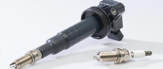
Philips LightGuide
Philips LightGuide New for winter 2012. Philips LightGuide daytime running lights consist of two LED strips that produce a continuous light, as opposed to individual LEDs. Compact size and compliance with GOST requirements. Our technicians will install Philips LightGuide at an affordable price.
- Depth: 20 mm.
- Width: 163 mm.
- Height: 34 mm.
Attenuation - yes. Price with installation: 8800 rub.
Legacy Philips models:
- Philips LED 4
- Philips LED 5
- Philips LED 8
The nuances of turning on running lights
The basic requirements regarding installation, technical parameters and connection of navigation lights are listed in paragraph 6.19 of GOST R 41.48-2004. In particular, the electrical functional circuit of the DRL must be assembled in such a way that the running lights turn on automatically when the ignition key is turned (the engine starts). In this case, they should automatically turn off if the headlights are turned on.
Clause 5.12 of this standard states that headlights (FGS) should be turned on only after the lights are turned on, with the exception of short-term warning signals. When connecting DRLs yourself, this feature must be taken into account.
Correct connection of DRLs is not limited to a well-thought-out functional diagram. It's time to think about the stabilization unit for LEDs. In the running lights themselves, resistors act as a current limiter; however, due to voltage drops, resistors cannot limit the current to the same level. That is why a voltage stabilizer in the running lights connection circuit is extremely necessary. Otherwise, the service life of LED DRL modules is significantly reduced due to constant changes in on-board voltage. Some car enthusiasts claim that it is possible to connect running lights without a stabilizer.
Connecting and installing an LED driver is a waste of time, because the DRLs on LEDs shine regularly for months without any stabilization...
However, this statement is easy to dispute. The fact is that with each voltage surge, more than 12 V appears on the LED module, the forward current through the LEDs exceeds the nominal value, which leads to overheating of the emitting crystal. The brightness of the LEDs decreases, such DRLs will no longer be able to fulfill their immediate task - to warn oncoming drivers from afar, and over time they will begin to flicker and fail.
Using LED DRLs without a voltage stabilizer means spending at least several hundred rubles every year on new modules and wasting time replacing them.
For ease of understanding, the circuits below are shown without using a stabilizer.
Switching on through dimensions or low beam
The second version of the DRL connection diagram involves using the power circuit of the side light bulb. To do this, the positive wire from the running lights is directly connected to the “+” from the battery. In turn, the negative wire is connected to the “+” of the side light, which is currently electrically neutral. As a result, the following current flow path is formed: from the “+” of the battery through the LEDs to the size, and then through the light bulb to the body, which serves as the minus of the entire circuit. Due to the low current consumption (tens of mA), the LEDs begin to glow, and the lamp spiral remains extinguished. If the driver turns on the side lights, then +12 V appears on the positive side of the side lights, the potentials on the DRL wires are equalized and the LEDs go out. The circuit goes into normal mode, that is, current flows through the side light bulbs.
This circuit solution has several disadvantages:
- running lights remain on when the engine is turned off, which is contrary to current regulations;
- the circuit will not work if LEDs are also installed in the dimensions;
- the circuit will not work correctly if the DRLs contain powerful SMD LEDs, the rated current of which is comparable to the current of a light bulb;
- For safety reasons, an additional fuse must be installed.
This connection method can be improved by connecting the positive wire of the LED module not to the “+” of the battery, but to the “+” of the ignition switch, thereby eliminating the first drawback. Some motorists use schemes for turning on running lights through a low beam lamp. That is, when the low beam is turned on, the DRLs automatically go out, but in other cases they work. In addition to the above disadvantages, this method does not comply with GOST R 41.48-2004 and traffic rules.
When parking a car at night, side lights are used to indicate it; the use of DRLs is prohibited.
How to change the reverse sensor on a VAZ 2107
Before replacing the sensor, it is advisable to clean the gearbox of dirt. If this is not done, it may get into the oil, which is located in the crankcase. Replacement of the VAZ 2107 reverse sensor is carried out in the following sequence:
Note: if the sensor is “stuck” and cannot be unscrewed with a wrench, you can try to unscrew it using a chisel and hammer. However, this must be done extremely carefully so as not to damage the gearbox housing, which is made of a fragile aluminum alloy.
Connection via a 4-pin relay from a generator or oil sensor
The following two methods have a common basis and imply the operation of daytime running lights only after the engine is started. The circuit for switching on DRL from the generator is based on switching a four-contact relay and a reed switch.
The DRL relay contacts are connected as follows:
- 30 – to the positive terminals of LED modules;
- 85 – to the positive wire to the dimensions;
- 86 – to any reed switch output;
- 87 and the second terminal of the reed switch - to the “+” of the battery.
After checking the reliability of all contacts, proceed to setup. To do this, start the engine and, by moving the reed switch near the generator, achieve its activation and a stable glow of the DRL. Then the reed switch is hidden in a thermal tube and fixed in the found place using nylon ties.
At the moment of starting the engine, and then the generator, the contacts of the reed switch and relay close, supplying power to the LED running lights. In this case, the side lamps remain turned off, since the current through the relay coil is small to light them.
How to make daytime running lights with your own hands
To make your own DRLs, you usually use cheap fog lights, LED strip, aluminum plates, silicone sealant and a soldering iron. The assembly sequence will be approximately as follows:
- First, the old fog lamp is disassembled and the internal filling is removed.
- Next, an aluminum plate is cut to the size of the flashlight body.
- A piece (or 2 pieces) of LED strip is cut to the size of the plate.
- An adhesive-sealant is applied to the degreased aluminum surface, and the LEDs are attached.
- All that remains is to use a soldering iron to connect the pieces of luminous tape and the electrical wire in series.
- The headlight is already assembled with a new filling.
To connect such DRLs, select one of the circuits suitable for a given car (it is better to connect via a DRL controller or via a relay and oil pressure sensor, as in the video below).
Installing daytime running lights on a car with your own hands becomes not only an interesting pastime. The result of the work will be a reason for pride for the car owner, because he managed to create a new image for his iron horse on his own.
Connection via 5-pin relay
Now it's time to learn how to connect running lights via a five-pin relay. The scheme is the most universal, and was assembled to eliminate the disadvantages of previous options.
First, about connecting the relay for DRLs:
- 30 – to the positive terminals of LED modules;
- 85 – to the positive wire of the side lamp;
- 86 – on the car body;
- 87a – to “+” from the ignition switch;
- 87 – do not connect (isolate).
The circuit with a five-contact relay works as follows. When you turn the key, +12 V is supplied to the DRLs, thereby turning them on. If you turn on the side lights or headlights, the relay will open contact 87a and close inactive contact 87. As a result, the DRLs will go out and the side lights will turn on. The circuit fully complies with the requirements of GOST and traffic regulations and can work with side lights even based on LEDs.
However, the circuit still has one negative point - the DRLs will turn on immediately after turning the ignition switch. That is, if you turn the key in the ignition but do not start the car, the DRLs will light up.
Despite the existing drawback, the circuit is quite successful, but in order to correctly connect the DRL via a five-pin relay, you will need to supplement the circuit with a voltage stabilizer.
This switching option is interesting because the path of current flow through the running lights is independent. This allows you to install light sources of any type and power in headlights and DRLs.
It couldn't be simpler
This is the simplest scheme, which involves connecting to a battery or generator as a power source.
Springs for a passenger trailer: which ones to choose and how to install them yourself Category: Passenger trailers
The scheme provides that the DRLs will be activated simultaneously with the engine starting. The point is to connect the plus to the positive terminal from the ignition switch of your Renault Logan or the same Lada Largus, and fix the minus on the car body in any convenient place. Everything looks simple and extremely logical. But you should not rush to conclusions, nor should you make such a connection. After all, it has an obvious drawback.
If the system is assembled according to this scheme, the diodes from the DRLs will start working constantly while the key is in the ignition switch. There is no question of any coordination with other headlights here. Therefore, such a connection contradicts GOST and traffic regulations.
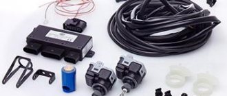
DRL control unit
The most reliable and simplest option is to connect DRLs without a relay, but using a special running lights control unit. It ensures that the DRL turns on after starting the engine, guarantees safe operation, protects against overloads and can be installed on cars with any type of lamps, including LEDs.
Unfortunately, among the variety of industrially manufactured DRL units, the vast majority do not comply with GOST and have mediocre build quality.
This applies, first of all, to products from AliExpress, which do not meet the requirements in almost all respects.
Among all the diversity, only 2 options can be noted: the Russian DayLight+ DRL control unit and German products from Philips and Osram. The DayLight+ control unit was developed by Russian radio engineer Fedor Isachenkov, taking into account all the features of the vehicle’s on-board network and has a number of positive aspects:
- there is built-in voltage stabilization;
- full compliance with GOST;
- the maximum long-term load power is 36 Watts (significantly less is required for DRLs);
- simplest connection diagram.
In addition to the points described above, the DayLight+ unit is universal and is suitable for all cars with an on-board 12-volt network, and also has good build quality and a high degree of protection from moisture and dust.
German products from Philips and Osram also have all the above-described advantages of the DayLight+ unit, however, German control units are supplied only together with daytime running lights and are more expensive.
DRLs or daytime running lights can be connected to the car in several ways. All of them involve connection via a generator or battery.
Main advantages
The main colors of LED lights used by drivers are bright blue or white. The advantage of this coloring is good illumination and efficiency.
Types of daytime running lights
Front lamp emitters, unlike ordinary headlights, are special industrial devices. They have many advantages, for example: reducing fuel consumption and saving battery power. Installation of DRLs does not cause any difficulties.
What to do if the reverse lights do not light up? More detailed information can be found here.
What is DHO
ATTENTION! A completely simple way to reduce fuel consumption has been found! Don't believe me? An auto mechanic with 15 years of experience also didn’t believe it until he tried it. And now he saves 35,000 rubles a year on gasoline! Read more"
Modern traffic regulations provide for the mandatory use of daytime lights. The solution was implemented for safety reasons, because a car with its lights on will be much more visible to other road users even during the day. As a result, the risk of accidents is reduced.
Today, traffic police officers can legally stop a vehicle that does not use daytime running lights. And the owner of the car will bear the same responsibility for this as if he did not have low-beam headlights or PTF.
Daytime lights are a mandatory element in the list of standard equipment of new car models. But this does not mean that all is lost for owners of used cars.
Despite the fact that for some Russian drivers, connecting the DRL is too expensive, it can be done without “raping” the family wallet.
Using low beam or PTF as an alternative, unfortunately, does not bring anything useful. The constant operation of optics leads to the fact that the headlights wear out faster, and as a result, such savings lead to even greater costs.
But you can really help save on service costs by connecting the DRL according to a scheme that is easy to implement with your own hands.
Only an independent connection diagram, preferably in accordance with the following mandatory rules:
- daytime LEDs go out a priori when the head optics (low beam, high beam or PTF) are activated;
- it must be possible to turn off the DRL using a separate button, without the use of extraneous tools;
- The running light must turn on randomly as soon as the engine is started.
Installation process
After purchasing regular or flexible DRLs with a turn signal function, you are faced with the question: how to connect new devices to the VAZ? This requires:
take a five-pin relay from a domestic manufacturer;
Five-pin relay of a domestic manufacturer
- to contact No. 30, take a positive charge from the ignition (alternatively, a wire from the button responsible for heating the rear window);
- connect connection No. 86 to the low beam using the button for activating the headlights and low beams;
- No. 85 - throw on ground;
- No. 88 - connect to DRL;
- No. 87 is not required during operation and is not connected to anything.
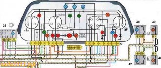
Connection diagram for daytime running lights on VAZ 2107
Relay - put it in the cabin. Under the car hood, run only the wiring that goes directly to the lighting fixtures. This connection diagram for the daytime running light on the VAZ 2107 automatically turns on the LEDs when the ignition key is inserted and turns them off when the engine is turned off. In addition, when the vehicle's low beams are on and the engine is running, the lights will go out and turn on again when the daytime running lights are turned off.
A simple diagram for connecting LED DRLs. Verified.
I did it myself according to this scheme:
Many will not understand why I made it more dependent on the starter, when it would have been possible to get by with the 1st relay from the gene, but before that I already had it that way, and when you turn the key to the ignition position, the DRLs would light up for a split second, even if current is the current on the control circuit, i.e. it jumps from the control circuit to the power circuit and ends up on the DRL, how to explain this? Arc or what?
Yes, and I recently became an electrician, and of course, while I’m “green” and my hands are itching, I want to experiment, so I did that, but now nothing blinks, but turns on with a slight delay after starting. The DRLs go out when the lights are on, but the other headlights don't.
Hi all. It is no secret to everyone that from November 20 you will need to drive with low beam headlights on (clause 19.5 of the traffic regulations) or you can use fog lights (clause 19.4 of the traffic regulations). Here I also offer a diagram for connecting daytime running lights (DRLs). Their installation is regulated by GOST R 41.48-2004 (I provide an extract from it) ************************************ *********** 6.19. Daytime running light 6.19.1. Installation Optional on vehicles. Prohibited on trailers. 6.19.2. Number Two. 6.19.3. Installation diagram There are no special instructions. 6.19.4. Placement 6.19.4.1. By width - the point of the surface visible in the direction of the reference axis that is furthest from the median longitudinal plane of the vehicle must be located at a distance of no more than 400 mm from the edge of the overall width of the vehicle. The distance between the inner edges of two visible surfaces must be at least 600 mm. This distance may be reduced to 400 mm if the overall width of the vehicle is less than 1300 mm. 6.19.4.2. In height - at a distance from 250 to 1500 mm above ground level. 6.19.4.3. In length - on the front of the vehicle. This requirement is considered to be satisfied if the emitted light does not interfere with the driver directly or indirectly as a result of reflection from mirrors (rear view mirrors and/or other reflective surfaces of the vehicle. 6.19.5. Geometric visibility Horizontal angle beta = 20° outward and inward. Vertical angle alpha = 10° up and down from horizontal 6.19.6 Direction Forward 6.19.7 Functional electrical diagram If installed, daytime running lights shall turn on automatically when the engine start/stop control is turned to the "on" position. The ability to activate and deactivate the automatic activation of daytime running lights without the use of a tool. Daytime running lights must turn off automatically when the headlights are turned on, except when the headlights are turned on for a short period of time to signal road users. **** **************************************** ************** Taking into account the requirements for turning on and off the DRL in automatic mode, I propose a diagram (I drew and developed it myself)
Scheme options
So, you can connect in several ways.
- The DRL turns on as soon as the ignition key is turned. The lights do not go out until the car engine stops. It is considered the simplest method, which does not involve the use of an on-board network. It is enough just to connect the negative from the lights to any place in the car body, and connect the positive from the lock to the output of the high-voltage module, always through a fuse.
- The same scheme, only the DRLs go out immediately as soon as the low beam is turned on. To implement this connection option, you need to adhere to the diagram described above, with the only difference being that the negative is connected to one of the positive wires of the low beam lamp. As soon as the low beam on the car is turned on, a positive impulse will appear on the minus DRL and the lights will go out. The DRLs will light up again as soon as the high beams are activated or the headlights are turned off.
- Connection diagram, which involves automatic connection of the DRL as soon as the car engine starts. It is considered the most reliable option for self-integrating LED daytime running lights. To implement this scheme, the minus of the DRL is connected to the car body, and the plus is connected to the relay contact.
Simple circuit with 4-pin relay
There is a simplicity in circuit number 1, implemented through a 4-pin relay. However, this option does not always satisfy the requirements of GOST, since the DRLs will shine separately from the head optics. The lights are not turned off by a push-button mechanism, everything happens automatically.
The photo above shows exactly this circuit, connected via a 4-pin relay. It implies the following procedure:
- when the engine starts, an impulse is sent from the generator to the relay, and the LEDs light up;
- As soon as the headlights are turned on, the DRLs turn off.
This connection method is also possible without using a generator. Then, instead, the voltage source will be the battery, the positive of which should be connected to the 30th contact in the photo.
It is also possible to connect the plus from the parking brake. In this case, as soon as the handbrake is activated, the daytime lights will go out - that's the button.
Circuit with 5-pin relay
It involves the use of 4 contacts. Ideal connection option for Priora cars. The difference from the above diagram is not only in the number of relay contacts. This circuit does not provide for the use of output 87. An alternative to ground is output 86.
The circuit with a 5-pin relay provides for the use of DRL control. The push-button mechanism is built between the generator and the 30th relay contact.
The operation of the DRL is as follows:
- the internal combustion engine is started, thereby the impulse from the generator goes to the 30th contact of the relay, and from there to the plus of the DRL;
- the lights come on, the minus is connected to any part of the car body;
- when the dimensions are used, the coil is activated, the 30th contact is integrated with the 87th, the pulse no longer arrives - the DRL is turned off.
With reed switch
In a circuit using a reed switch, three important automotive systems are simultaneously activated: the generator, battery and relay.
The photo above shows a detailed connection diagram for the option using a generator. The plus is integrated, as can be seen from the diagram with point 30. The relay contact, marked with point 87, is integrated with the battery positive. Another relay contact, marked with number 85, is connected to the vehicle ground through the DRL.
Attention. This scheme implies the mandatory use of a reed switch - a device capable of changing the state of a connected electrical circuit when exposed to a magnetic field.
The contact marked on the diagram with point 86 is connected to the reed switch. From the reed switch there is a connection to the plus of the generator.
Thus, the scheme implies the following. As soon as the internal combustion engine starts, the driver activates the reed switch with a button, the relay is activated, and the DRL turns on. The reed switch must be packed in thermopolymer and securely fixed to the generator.
Advice. It is important that the reed switch is fixed exactly in the place of the generator where the relay would operate.
Without reed switch
A variation of circuit number 3, only without using a reed switch. In this case, the contact marked 86 is integrated with the oil pressure lamp in the instrument panel. Thus, the option of turning on the DRL after the engine is started is supported.
It is noteworthy that this scheme is much easier to implement with your own hands than the option with a reed switch.
Video: how to connect DRL from a generator
As you can see, connecting the DRL to the vehicle’s on-board network is carried out using several circuits. The plus is taken from the output of the generator, less often from the battery.
Forget about fines from cameras! An absolutely legal new product - Traffic Police Camera Jammer, hides your license plates from the cameras that are installed in all cities. More details at the link.
- Absolutely legal (Article 12.2);
- Hides from photo and video recording;
- Suitable for all cars;
- Works through the cigarette lighter connector;
- Does not cause interference to radios and cell phones.
Front lights
The front part of the car usually attracts more attention, so amateurs begin to tune primarily the headlights.
Evil headlights
It’s very easy to give your car a menacing, gloomy and even evil look: just perform tuning like “evil headlights”. This is one of the easiest ways to give the “seven” an unusual appearance.
Depending on the owner’s capabilities, tuning can be done using a variety of materials:
- thin plywood;
- sheet metal;
- tinting film;
- paints.
The “evil” squint of a car gives you goosebumps.
The essence of this tuning is as follows: cover part of the headlight so that the remaining uncovered headlight resembles evil eyes. If any materials from plywood or metal are selected, then a blank is cut out in advance and glued into the cavity of the headlight. Using film or paint is even easier - just remove the headlight and apply darkening on the inside.
Tuning headlights from plywood painted black
Angel eyes
In tuning, angel eyes are the luminous rings on the “face” of a car - like a BMW. Today everyone can afford this lighting option - it’s inexpensive and fast. In addition, the body of the VAZ 2107 will somewhat resemble an expensive BMW and thereby increase the status of the owner.
Headlights that are very unusual for the “Seven”
There are several technical solutions for making angel eyes with your own hands. The easiest option is to use LEDs. To work you will need:
- white LEDs 5 mm - 2 pcs.;
- 0.25 W resistor;
- wiring;
- transparent rod made of organic glass or plastic (diameter 8–10 mm);
- auxiliary materials (soldering iron, hair dryer, drill and glass jar).
The work is quite painstaking:
- Take the rod and clamp it in a vice.
- Using a drill, drill holes for the LEDs at both ends of the rod.
- Give the rod the shape of a ring - bend it around the jar and heat it with a hairdryer so that the workpiece remains in this shape.
- Solder wires to the LEDs, connect a resistor to one of the wires.
- Assemble an electrical circuit similar to the circuit of lighting devices that is already available on the “seven”.
- Insert the LEDs into the holes of the workpiece and glue them with superglue.
Video: how to make angel eyes
You can buy ready-made angel eyes at a car store - this will make it much easier to connect new lighting fixtures to the standard equipment of the car.
Using LEDs of different shades, you can achieve an even more impressive effect.