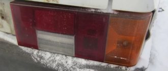
The functioning of the rear lights of any car is necessary for road safety reasons. These devices at the rear of the car perform a lighting and information function (warn road users about the movement of the car).
On VAZ 21099 and other models, the lights turn on automatically when changing gears and moving the car backwards.
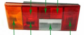
Structurally, the lights at the rear of the car combine the following components of the lighting system:
- reversing lighting;
- side lighting;
- brake lights;
- turn signals;
- emergency alarm.
Rear view lights for VAZ 21099
The structure of the lighting devices is as follows:
- body made primarily of plastic (in some cases glass);
- lamp holder;
- latch for holding wires;
- diffuser of light rays for uniform illumination of the road surface. It is glued to the back of the product body, so if it breaks, it needs to be replaced along with the body.
The device of the rear light on VAZ 2109-2108 and 21099
The following types of rear lights can be installed at the rear of a VAZ 2108 or 2109:
- incandescent lamps. Inexpensive, but they break down relatively quickly and are not bright enough. Such lamps burn with a yellow light, which is not very visible in unfavorable weather conditions;
- halogen light bulbs . They are considered more modern and durable, since air is pumped out of their flask and inert gas is pumped in. There are models with H1 and H3 sockets on sale;
- LEDs . They burn with a cool white light and last several times longer than incandescent lamps. They are sold in strips and today often replace obsolete incandescent lamps.
LED tail lights for VAZ 2108
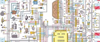
Relay and fuse box diagram 2109
Fuse block 2114-3722010-18
K1-relay for turning on headlight cleaners; K2-relay-breaker for direction indicators and hazard warning lights; K3 - windshield wiper relay; K4-relay for monitoring the health of lamps; K5-power window relay; K6 - relay for turning on sound signals; K7-relay for turning on the electric heating of the rear window; K8-relay for high beam headlights; K9-relay for low beam headlights; F1-F16 - fuses.
Fuse block 2114-3722010-60
K1 - Headlight wiper relay, K2 - Turn signal and hazard warning relay, K3 - Windshield wiper relay, K4 - Brake light and parking light relay, K5 - Power window relay, K6 - Horn relay , K7 - Rear window heating relay, K8 - Headlight high beam relay, K9 - Headlight low beam relay, F1 - F16 - Fuses, F1 - F20 - Spare fuses.
Source
Installation and testing of rear lights of VAZ 2109
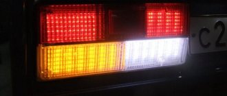
The rear lights (headlights) of the VAZ 2108, VAZ 2109, VAZ 21099 have the following bulbs: 1) Brake lights. 2) Dimensions. 3) Reverse. 4) Turns. 5) Fog lamp.
Tail light board
A wiring harness goes from the mounting block to the rear lights. The purpose of each individual wire in the harness can be understood by its color: 1) Brake lights - red 2) Dimensions - yellow 3) Reverse - green. 4) Turns - blue. 5) Fog light - orange-black.
Remove the connector from the rear light board
Naturally, you need to understand that if the car is old and a lot of people have done the wiring, then the color match of the wire to its purpose may be disrupted. That is, the red wire can be converted not to brake lights, but, for example, to dimensions. But in general, this is a very important point: AvtoVAZ developers specifically marked the functional purpose of the wire with a certain color to make it easier to use.
Flashlight board
If some light signal in the rear headlight of a VAZ 2109 does not work, then before climbing into the mounting block and opening the electrical circuit, we check the following: 1) The reliability of fastening the rear light mass to the body. 2) Check the reliability of fastening the wire connector to the headlight. 3) Integrity of the light bulb 4) Quality of contact between the light bulb and the flashlight board. It often happens that everything is intact, the light bulb and the mass are good, and 12 Volts come to the light bulb, but it does not light. The reason is poor contact between the light bulb and the board. In this case, you need to clean both the light bulb base and the area on the lantern with fine sandpaper. As one smart person said: “Electrics is the science of contacts.” To disassemble the rear light of the nine, first remove the protective plastic cover. Then disconnect the black wire of the flashlight from ground. Then we remove the connector from the flashlight board and remove the board itself with the bulbs from the headlight housing. If it is necessary to replace the headlight itself, then unscrew the remaining bolts securing the headlight to the car frame and remove it.
Lantern body
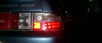
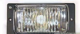
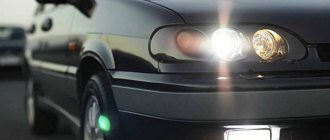
There is one important point that many owners of the ninth model Zhiguli do not know. This is the rear fog light. It is turned on by a button between the hazard warning button and the heated rear window. The rear fog light will only work if: 1) The ignition is turned on. 2) Low beam headlights are on. 3) The flashlight power button is pressed. The fog light bulb is the only one that has a reflector inside the headlight. Thanks to this reflector, the glow of the lantern becomes brighter.
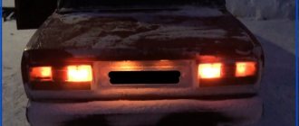
Enabled clearance
Rear fog light on
Rear light bulb power: Dimensions 5 Watt Fog light 21 Watt Reverse 21 Watt Stop light 21 Watt Turn signal 21 Watt
Fuse blown
No. 6 for mounting block 17.3722, F3 for 2114.
If it burns out, replace it with a new one. Subsequently, it will be necessary to find out the reason for the blown fuse, perhaps a small short circuit somewhere.
Fuse No. 6 for brake lights (stops) VAZ 2108, 2109, 21099 with mounting block 17.3722
Video “Refinement of rear lights”
You can learn more about modifying the rear lights on the VAZ 2109 from the author of the video, Dmitry Sergeevich.
The rear lights (headlights) of the VAZ 2108, VAZ 2109, VAZ 21099 have the following bulbs: 1) Brake lights. 2) Dimensions. 3) Reverse. 4) Turns. 5) Fog lamp.
Rear light board for VAZ 2108, VAZ 2109, VAZ 21099
A wiring harness goes from the mounting block to the rear lights. The purpose of each individual wire in the harness can be understood by its color: 1) Brake lights - red 2) Dimensions - yellow 3) Reverse - green. 4) Turns - blue. 5) Fog light - orange-black.
We remove the connector from the rear light board of VAZ 2108, VAZ 2109, VAZ 21099
Naturally, you need to understand that if the car VAZ 2108, VAZ 2109, VAZ 21099 is old and there are a lot of people doing the wiring, then the color match of the wire to its purpose may be violated. That is, the red wire can be converted not to brake lights, but, for example, to dimensions. But in general this is a very important point: the developers of the VAZ 2108, VAZ 2109, VAZ 21099 specifically marked the functional purpose of the wires with a certain color to make it easier to use.
Flashlight board VAZ 2108, VAZ 2109, VAZ 21099
If some light signal in the taillight of a VAZ 2108, VAZ 2109, VAZ 21099 does not work, then before climbing into the mounting block and opening the electrical circuit, we check the following: 1) The reliability of fastening the mass of the taillight to the body of the VAZ 2108, VAZ 2109, VAZ 21099. 2) Check the reliability of fastening the wire connector to the headlight. 3) Integrity of the light bulb 4) Quality of contact between the light bulb and the flashlight board. It often happens that everything is intact, the light bulb and the mass are good, and 12 Volts come to the light bulb, but it does not light. The reason is poor contact between the light bulb and the board. In this case, you need to clean both the light bulb base and the area on the lantern with fine sandpaper. As one smart person said: “Electrics is the science of contacts.” To disassemble the rear light of a VAZ 2108, VAZ 2109, VAZ 21099, first remove the protective plastic cover. Then disconnect the black wire of the flashlight from ground. Then we remove the connector from the flashlight board and remove the board itself with the bulbs from the headlight housing. If it is necessary to replace the headlight itself, then unscrew the remaining bolts securing the headlight to the car frame and remove it.
Useful tips
The VAZ 2109 wiring diagram is necessary without any intention of making changes to the car’s structure, because during operation the wiring is subject to:
Accordingly, the owner is required to perform a preventive inspection of the standard wiring in order to identify insulation violations and mechanical damage. Timely detection of a malfunction will allow you to quickly correct and prevent more significant failures in the operation of the vehicle’s electronic devices.
Conclusions: we hope that the issues covered in this article will protect you from thoughtless intervention in the electrical circuit of your car. And if you need to replace the standard wiring, you will do it in accordance with the manufacturer’s recommendations.
VAZ 2109 generator circuit
If you lose charge, this is most often due to a failure of the generator, and most often it is the generator brushes, but it happens that there are winding breaks and a short circuit in the circuit or an open circuit. In this case, I recommend that you familiarize yourself with this generator circuit for the VAZ 2109.
Numerical designations on the diagram
| 1. Generator. | 2. Negative valve. | 3. Additional diode. |
| 4. Positive valve. | 5. Battery discharge warning lamp. | 6. Instrument cluster. |
| 7. Voltmeter. | 8. Mounting block. | 9. Additional resistors of 100 Ohm, 2 W. |
| 10. Ignition relay. | 11. Ignition switch. | 12. Rechargeable battery. |
| 13. Capacitor. | 14. Rotor winding. | 15. Voltage regulator. |
How to fix starter malfunctions with your own hands
The electrical component of the starter consists of the following structural elements:
- winding;
- brush assembly;
- solenoid relay.
When checking the solenoid relay, skip the starter operation, bypassing its switching. The relay has 3 terminals at once, one of which is the control terminal. The remaining 2 large terminals, located at the input to the battery and at the output of the starter, are closed using a screwdriver or wrench. Closing for a short period of time is enough, the main thing is that the tool you are using does not touch the metal body directly under the hood.
Remember that starting the engine in this way is prohibited, because the main gear of the device does not engage.
Most likely, the contact planes on the inner plane simply burned out, and therefore a dielectric layer of metal oxides formed on top. To burn the contacts, there is no need to make great efforts; just one start of the VAZ-2109 engine is enough.
There are 2 ways to repair the VAZ-2109 solenoid relay:
- Dismantle the device and disassemble it into components, clean the contacts.
- If it is financially possible, it is better to replace the relay completely. Practice shows that if a relay fails, the contacts will have to be cleaned more and more often to restore its operation. If you want the repaired relay to last a long time, give preference to this option for repairing the starter if the device does not spin or click.
Repair and tuning of rear lights on the legendary Nines - VAZ 2109
The rear lights of the VAZ 2109 can not only cause inconvenience with their breakdowns and malfunctions. If, of course, this happens, below you can find out how to eliminate some of them
It is also important that the lights can be tuned
Causes of failure of the rear parts of the lighting system and driver actions
You can find out what the breakdown may be and how to solve the problem below. We will talk about modified nines.
Possible malfunctions of brake lights and their elimination
- Due to a voltage drop, a short circuit may occur and the paws will burn out.
- If it's time to strip the wires because the contacts have oxidized and the terminals do not conduct current well enough.
- Often, in the event of a voltage drop, it may be necessary to remove and replace fuses.
- If the reverse sensor contacts are broken or damaged.
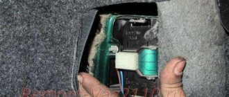
Removing the brake light switch sensor
In case of the problems listed above, the easiest way, of course, is to install a new lamp. This happens without any difficulty: you just need to turn off the lights, open the trunk and remove the wiring block. After this, holding the fixing elements that are installed on the sides, remove the panel and unscrew the lamp. In its place, install a new light device and assemble the assembly in the reverse order. If we talk about stops, both lamps and one of them may not work, that is, only in one headlamp.
If such a problem occurs, it is necessary to immediately diagnose:
- Check the fuse and, if necessary, replace it with a new one. Fixing a breakdown is not enough, because, as in the case of human diseases, a burnout may be a fault in the system that needs to be corrected. If this is not done, you can change the device until the end of the life of the VAZ 21099. One of the reasons may be a short circuit.
- If the wiring in the signal lamp sockets has oxidized, the lamp needs to be twisted a little in the socket to scrape off the damaged layer. To make the work done more effective, you can clean the contacts with sandpaper.
- If the lamps in the stops burn out, you need to replace it with a new one and check whether the system will work. And if the contacts are bad, they need to be cleaned both on the board and on the wire block.
- If the tracks in the headlight circuit board are burnt out, then you can remove the board and visually diagnose its integrity. If there are burnt tracks, they can be modified by replacing the wiring.
- The sensor is faulty or the electrical circuit is broken. First, you need to remove the red and white wires from the sensor and connect them with a piece of wire. If the brake lights come on, then the sensor needs to be replaced; if not, you need to check the electrical circuit. It needs to be checked for broken contacts.
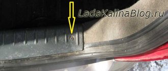
Removing and replacing rear lights
- It is best to make the replacement before wiring problems begin.
- To work you need to remove the lights. On the VAZ 21099 it is hidden by a plastic decorative trim in the trunk.
- Now unscrew the fixing screws on the trim and remove them.
- Disconnect the block with wires and carefully remove it, being careful not to damage the board, because it sits tightly in place.
- Now, using a 10mm wrench, unscrew the 4 nuts securing the headlight housing. Remove the part from the machine. Now you can install the new part and calmly begin the replacement.
- The collection is done in reverse order (the author of the video is Automaniac1994).
Replacement process
The rear lights are attached to the body of a VAZ 21099, 2108 or 2109 car using 4 nuts. To dismantle the lighting system you will need:
The operating algorithm is as follows:
- To access the nuts, remove the 21099 luggage rack at the appropriate location (if the rack is installed).
- Disconnect the power plug that is attached to the board.
- Unscrew the 4 nuts using a wrench.
- When removing the last nut, hold the taillight outside to prevent it from falling and breaking.
- After removing all 4 nuts, remove the light.
When installing a new headlight on the rear of model 21099, do not forget to connect the wiring to ground, which is attached to one of the studs.
Flashlight tuning process:
Fuse box of the new VAZ 2109 model
1. 8A Backup fuse2. 8A Backup fuse3. 8A Backup fuse4. 16A Coil of the radiator fan relay, electrical circuit of the switch and heater motor5. 3A Hazard warning switch in turn signal mode, turn signal breaker, turn signal switch, turn signal indicator light, turn signal indicator light, reverse optics switch, reverse lights, tachometer, voltmeter, gasoline level indicator, gasoline level sensor, gasoline level indicator light, coolant temperature indicator, temperature sensor, warning lamp and emergency oil pressure sensor, brake emergency lamp, brake system hydraulic switch, handbrake switch6. 8A Switch and brake light bulbs, interior lighting7. 8A Room lighting lamps, indicator lamp for turning on the parking lights, illumination lamp for the heater and cigarette lighter handles, glove box illumination lamp, switch and instrument panel illumination lamp8. 16A Horn, horn switch, radiator fan motor9. 8A Left side lamp, left rear side lamp 10. 8A Right side lamp, right rear side lamp, fog light switch, fog light indicator lamp 11. 8A Turn signal switch and breaker, turn signal lamps, warning lamp in emergency mode12. 16A Cigarette lighter, socket for carrying lamp13. 8A High beam of the right headlight14. 8A Main beam of the left headlight, high-range optics warning lamp 15. 8A Low beam of the right headlight16. 8A Low beam left headlight
Wiring diagram for power windows on a VAZ 2109
Tired of lifting windows with ordinary “oars”? Then install electric windows using the wiring diagram for electric windows on a VAZ 2109.
Numerical designations on the diagram
| 1. Mounting block. | 2. Ignition relay. | 3. Ignition switch. |
| 4. Right door electric window motor. | 5. Left door electric window motor. | 6. Right door power window switch. |
| 7. Left door power window switch. | K7. Power window power relay. | A. To terminal “30” of the generator. |
| B. To the wiring harness block connected to the heater lever illumination display. |
Dimensions + turn signals in mirrors - Community “VAZ: Repair and Improvement” on DRIVE2
Hello everyone, maybe someone will be interested in my option for connecting the lights to the turn signals. After installing the mirrors, I wanted the mirrors to light up like the lights and at the same time the repeater would blink, after a week of torment and searching for the correct circuit, I achieved the desired result.
A circuit of 2x 5 contact relays, each relay to its own mirror, nothing complicated, the minus for the repeaters was powered from a guitar (blue with a black stripe left turn signal, just blue right turn) + took the dimensions from the light switch (block number 6) turn signal in the mirror and the turn signal in the headlight are activated simultaneously.
scheme
2 relays 5 pin
guitar, located under the steering cover (where the knob turns on the turn signals)
I took advantage of the opportunity and glued the steering casing or whatever it was correctly... otherwise it creaked and rattled on bumps)
STP and bitoplast
www.drive2.ru
Equipment diagram for VAZ-2109 injector
The VAZ 2109 wiring for the injector has many connectors for connecting sensors to the computer.
- TPS (throttle position sensor);
- DPKV (crankshaft position sensor);
- DT (temperature sensor);
- DSA (vehicle speed sensor);
- Canister purge valve;
- MAF (mass air flow sensor);
- DD (knock sensor) and others.
Since the mid-90s, VAZ 2109 began to use engines with an injection system, which greatly changed the electrical layout of the engine compartment and instrument panel. Below is an electrical diagram of a 1999 car with an ECM type GM ISFI-2S and January 4/4.1.
- 1 - nozzle system;
- 2 - candles;
- 3 — ignition control module;
- 4 — diagnostic connector;
- 5 — General Motors or January controller;
- 6 — connector for connecting the instrument cluster;
- 7 — main relay of the system;
- 8 — fuse for power supply wiring of the controller and ignition system module;
- 9 — protection of the speed sensor and air flow meter circuits;
- 10 — fuel supply pump power protection;
- 11 — fuel pump controller;
- 12 — engine temperature meter;
- 13 — idle system;
- 14 — detonation meter;
- 15 — tank purge system for collecting fuel vapors;
- 16 — crankshaft position meter;
- 17 — speed meter;
- 18 — air flow meter;
- 19 — lambda probe;
- 20 — throttle position angle meter;
- 21 — electric fuel pump complete with fuel level sensor;
- 22 — connection of the ignition system;
- 23 — control lamp;
- 24 — ignition switch;
- 25 - switching block;
- 26 — radiator cooling fan.
Engine compartment modifications
In addition to replacing the power unit after it has exhausted its life, there are many components in the engine compartment whose wiring also needs to be replaced:
- high-voltage wires from the ignition unit;
- wiring of various control sensors;
- battery power cables (connections are most susceptible to corrosion).
Numerous sensors in the engine compartment require special monitoring:
- Coolant temperature sensor - if the electrical wiring is faulty, the driver will not notice overheating of the power unit;
- Brake fluid level sensor in the expansion tank - a leak or low level can lead to brake system failure;
- ABC system sensors - oxidation of contacts or disruption of wiring integrity can lead to system failure;
- Exhaust gas sensor - based on its readings, the electronic unit “prepares” the fuel-air mixture. If the sensor does not work, gasoline consumption will increase.
A useful addition to the functionality of the car is the acquisition of a modern anti-theft system.
Installing a modern alarm system is a special topic, since its work affects several main components and systems of a VAZ family car:
- General electrical system;
- Supply system;
- Sound and light circuit and actuators (side lights, headlights, sound signals);
- Standard immobilizer.
General alterations
Installing additional fog lights is a general modification because:
- Affects equipment in the engine compartment;
- Interferes with the instrument panel inside the cabin;
- Connects to the vehicle's standard power supply system;
- Attached to the power body.
To install and connect fog lights, you will need a wiring diagram for the VAZ 2109, because the package includes:
- Connecting wires;
- Terminal blocks;
- Switching relay;
- Actuators (buttons);
- A backlight lamp (or LED) indicating the status of lighting fixtures.
Injection engine
The VAZ 2111 engine is built, one might say, on the basis of the VAZ 21083 - the block and cylinder head remain the same. Only the parts of the connecting rod and piston group have undergone minor changes - on the VAZ 21083 engine the piston pin is pressed into the connecting rod head, on the VAZ 2111 it has a loose fit. The connecting rod, pin and piston assembly are interchangeable.
The engine power supply and ignition systems have radically changed - instead of a carburetor, a ramp with injectors is installed on the intake manifold, injecting fuel into the inlet channels of the cylinders. The fuel pump is electric, installed in the fuel tank. Changing the quality of the fuel mixture and ignition timing is carried out by an electronic control unit.
The change in the power system did not affect the rated engine power (70 hp), but improved its traction characteristics - the maximum torque on the injection VAZ 21099 is achieved at 2800 rpm, on the carburetor - at 3400 rpm.
For car enthusiasts, in terms of operation and maintenance of the injection VAZ 21099, the changes affected the identification of problems in the engine control system. The same work as changing the oil, timing belt or even a blown cylinder head gasket is carried out in the same way for both engines.
VAZ 2109 fuse diagram
Has the fuse blown again? Because you loaded your VAZ 2109 with a powerful light or installed a sub for which the wiring and fuse box were not designed? Then this fuse diagram will come in handy!
| № | Ampere | Purpose |
| 1 | 8 | Right fog lamp |
| 2 | 8 | Left fog lamp |
| 3 | 8 | Headlight cleaners (at the moment of switching on) Headlight cleaner switching relay (contacts) Headlight washer switching valve |
| 4 | 16 | Headlight wiper motor Headlight wiper relay (winding) Heater motor Window washer motor Rear window wiper motor Rear window washer timing relay Windshield and rear window washer activation valve Cooling system electric fan relay relay coil Coil of the rear window heating relay coil Rear window heating control lamp Wardrobe lighting lamp box |
| 5 | 8 | Turn indicators in turn signal mode and the corresponding indicator lamp Rear lights (reversing lamps) Indicator lamp for fuel reserve, oil pressure, parking brake, brake fluid level, carburetor choke Voltmeter and indicator lamp for charging the battery Gearmotor and windshield wiper switch relay Generator excitation winding (at start-up) “STOP” indicator lamp Coolant temperature and fuel level indicators |
| 6 | 8 | Rear lights (brake lights) Body interior light Power windows and power window relay |
| 7 | 8 | License plate lights Engine compartment lamp Indicator lamp for turning on side lighting Instrument lighting lamp and cigarette lighter lamp Heater lever illumination panel |
| 8 | 16 | Engine cooling fan electric motor and its activation relay (contacts) Sound signal and its activation relay |
| 9 | 8 | Left headlight (side light) Left rear light (side light) |
| 10 | 8 | Right headlight (side light) Right rear light (side light) |
| 11 | 8 | Direction indicators and hazard warning relay (in hazard mode) Hazard warning lamp |
| 12 | 16 | Heated rear window element and heating relay Cigarette lighter Socket for portable lamp |
| 13 | 8 | Right headlight (high beam) |
| 14 | 8 | Left headlight (high beam) High beam indicator lamp |
| 15 | 8 | Left headlight (low beam) |
| 16 | 8 | Right headlight (low beam) |
| Relay | ||
| K1 | Rear window washer time relay (451.3747 / 2108-3747110, 2108-3747110-06) | |
| K2 | Relay-breaker for direction indicators and hazard warning lights (493.3747 / 2108-3747010-02) | |
| K3 | Windshield wiper relay breaker (522.3747 / 2108-3747710) | |
| K4 | Contact jumpers in place of the lamp integrity monitoring relay. Lamp integrity monitoring relay (4402.3747 / 21083-3747410, 21083-3747410-06) | |
| K5 | Headlight high beam relay (113.3747 / 2105-3747210-10, 2105-3747210-12) | |
| K6 | Headlight cleaner relay (112.3747 / 2105-3747210, 2105-3747210-02) | |
| K7 | Power window relay (13.3747 / 2105-3747210-10, 2105-3747210-12) | |
| K8 | Relay for turning on sound signals (13.3747 / 2105-3747210-10, 2105-3747210-12) | |
| K9 | Relay for turning on the electric cooling fan (13.3747 / 2105-3747210-10, 2105-3747210-12) | |
| K10 | Relay for turning on the heated rear window (13.3747 / 2105-3747210-10, 2105-3747210-12) | |
| K11 | Relay for low beam headlights (13.3747 / 2105-3747210-10, 2105-3747210-12) |
What can be changed in the electrical circuit
Let's figure out what exactly car owners undergo alterations.
Moreover, we will indicate only those alterations that are not prohibited by the manufacturer and current regulations:
- Installation of a new instrument panel;
- Alteration of internal (interior) lighting;
- Installation of additional turn signal indicators in the rear view mirrors;
- Installation of additional headlights (fog lights);
- Installation of an acoustic and multimedia system;
- Immobilizer installation.
Interior modifications
Many owners come to mind with the desire to improve the lighting in the car interior.
Let us remind you that inside a passenger vehicle there are several places equipped with lighting sources:
- The salon itself (interior lighting);
- Glovebox;
- Cigarette lighter;
- Instrument panel (instrument cluster lamp and symbol lamp)
If you, as the owner, like a high panel in the cabin, then you cannot do without replacing the standard wiring. Because the:
- Control devices have a different location on the panel;
- The standard length of wires is not enough;
- Terminal blocks may also differ.
Connection diagram
Before we talk about typical malfunctions of the VAZ 2110 rear light, let’s look at the electrical diagram for connecting it to the on-board network.
Electrical circuit for powering external lighting devices of the VAZ 2110
We are interested in the following positions:
- 2 – mounting block;
- 3 – external lighting switch;
- 4 – ignition switch;
- 6 – rear marker lamps;
- 7 – brake light lamps;
- 10 – reverse signal switch;
- 11 – brake light switch;
- 13 – reverse indicators.
The scheme is quite simple and does not require any special explanation. The side light is controlled by the external lighting switch 3. The reversing lamps are activated by limit switch 10 located on the gearbox. The brake signal turns on limit switch 11 - it is located in the cabin above the brake pedal and is activated when you press it. The side light turns on, bypassing the ignition switch, the brake and reverse signal - through it, and they can only be activated when the ignition is on.
Connection diagram for turn signals VAZ 2110
Here we need the following positions:
- 2 – mounting block;
- 3 – ignition switch;
- 4 – alarm switch;
- 6 – direction indicator lamps in the rear lights;
- 7 – direction indicator switch;
- K3 – relay-interrupter of direction indicators.
Design features, useful tips
Design features, useful tips
Repair and operation manual - Electrical equipment - Design features, useful tips The headlight switching diagram is shown in Fig. 9.15. The low and high beam headlights on a VAZ 2108, VAZ 2109, VAZ 21099 are switched on using auxiliary relays K5 and K11 (K8 and K9 for mounting block 2114). The control voltage to the relay windings is supplied from the headlight switch 6 if the exterior lighting switch 4 is fully pressed.
Regardless of the position of the switch key 4, you can briefly turn on the high beam headlights by pulling the headlight switch lever 6 towards you. In this case, voltage is supplied to contact “30” of switch b from contact “INT” of ignition switch 3. Some VAZ 2108, VAZ 2109, VAZ 21099 vehicles are equipped with a hydraulic headlight leveler, which is used to adjust the headlight angle from the driver's seat depending on the load on the vehicle.
The diagram for switching on external lighting on a VAZ 2108, VAZ 2109, VAZ 21099 car is shown in Fig. 9.16. The side light is turned on by switch 5 of the external lighting. Until 1988, a system was used to turn on the parking lights in the parking lot. The parking light was turned on by switch 6 if the ignition key 11 was in position III (parking). At the same time, the side light lamps on the left or right side of the car came on, depending on the position of switch 6.
The diagram for switching on the direction indicators and hazard warning lights on a VAZ 2108, VAZ 2109, VAZ 21099 is shown in Fig. 9.17. The turn indicators on the right or left side are turned on by switch 9. In emergency mode, switch 8 turns on all turn indicators. The flashing of the lamps is ensured by the relay-breaker K2.
Useful tips
If the headlights on a VAZ 2108, VAZ 2109, VAZ 21099 car suddenly start to shine dimly, and when the turn signal is turned on, the side light lamp begins to blink - restore contact of the ground wire with the car body.
Make it a habit to regularly change your bulbs (especially your headlights). Over time, the lamp bulb becomes cloudy and the brightness of the lamp decreases. Moreover, this process occurs quite slowly and the driver does not notice the gradual deterioration in road illumination.
Recently, more and more cars are appearing with headlights that shine like a Christmas tree in various shades of blue. All this is called “xenon” and is considered very cool. There is no doubt, xenon headlights, installed as standard on the latest models of foreign cars, illuminate the road much better, and the car looks much more impressive with them. It is not surprising that many are also trying to improve their car, especially since now a lot of “xenon lamps” of various manufacturers (most often Chinese) have appeared on the shelves. Don't buy it cheap - these lamps have nothing in common with real xenon discharge lamps without filaments. These are ordinary lamps with painted glass. The light transmission capacity of such glass is significantly lower than that of standard lamps; the filaments of fakes, as a rule, are set out of focus, and a headlight with such a lamp, while outwardly effective, illuminates practically nothing, and additionally mercilessly blinds oncoming drivers. In addition, manufacturers of such lamps, in order to compensate for the decrease in luminous flux, increase their power beyond the norm. Often their installation leads to melting of the wire insulation and burnout of the printed circuits of the mounting blocks. And a fire is also possible. It’s better not to buy a headache with your money, but buy high-quality ordinary halogen lamps.
Sooner or later, the bulbs in the taillights burn out. It would seem that it would be simpler - take a new light bulb, suitable for the size of the base and voltage, and install it in place of the burnt out one. However, keep in mind that the rear lights use lamps with the same base, but of different power: 4W and 21W. And this is not an insignificant detail: 4-watt lamps are installed for side lights, and 21-watt lamps are installed in turn indicators and brake lights. Do not confuse lamps. If you install low-wattage bulbs in your brake lights and turn signals, other drivers simply won't see your signals in inclement weather. And powerful lamps in “dimensions” will greatly disturb drivers driving behind and irritate them. Their attitude towards you will be corresponding.
Rice. 9.15. Diagram for switching on headlights and fog lights on a VAZ 2108, VAZ 2109, VAZ 21099:
1 — block headlights; 2 — mounting block; 3 — ignition switch; 4 — external lighting switch; 5 — rear lights; 6 — headlight switch; 7 - rear fog light circuit fuse; 8 — rear fog light switch; 9 — instrument cluster with indicator lamps for high beam headlights (right) and rear fog light (left); K5 - headlight high beam relay; K11 - low beam headlight relay. A - view of the headlight plug connector: a - low beam plug; b — high beam plug; c — side light plug; g - ground plug. B - to terminal “30” of the generator.
Rice. 9.16. External lighting switching diagram with fragment (a) of the parking light system connection diagram (for VAZ 2108, VAZ 2109, VAZ 21099 cars produced before 1988):
1 — engine compartment lamp switch; 2 — block headlights with side light lamps; 3 — engine compartment lamp; 4 — mounting block; 5 — external lighting switch; 6 — parking light switch in the steering column switch; 7 - instrument cluster with indicator lamp for external lighting; 8 — rear lights with side light lamps; 9 — license plate lights; 10 — instrument lighting switch; 11 — ignition switch; 12 — contact jumpers at the installation site of the lamp health monitoring relay; A - to the “INT” terminal of the ignition switch; B - to terminal “P” of the ignition switch; B - to plug “6” of block Ш1 of the mounting block; G - to instrument lighting lamps and to backlight lamps for displays and switches.
Rice. 9.17. Scheme for switching on direction indicators and hazard warning lights on a VAZ 2108, VAZ 2109, VAZ 21099:
1 — block headlights with front direction indicators;
2 — side direction indicators; 3 — mounting block; 4 - ignition relay; 5 — ignition switch; 6 — instrument cluster with indicator lamps for direction indicators (top) and hazard warning lights (bottom); 7 — rear lights; 8 — alarm switch; 9 — direction indicator switch in the steering column switch; K2 - relay-interrupter for direction indicators and hazard warning lights; A - to terminal “30” of the generator; B — terminals of the rear light printed circuit board: a — to the side light lamp; b - to the fog light lamp; c - to the turn signal lamp; d — to the reversing lamp; d - to mass; e - to the brake light lamp. Design features of the headlights of the VAZ-2108, VAZ-2109, VAZ-21099
To illuminate the road at night, two block headlights (right and left) are installed. They consist of rectangular headlights with head and side light lamps, interlocked with the side turn signal section. The headlight units are attached to the front of the car with four 28 studs and nuts with a serrated edge, which protect them from loosening themselves. The low and high beam headlights are switched by the left lever of the steering column switch 43 if the exterior lighting switch is turned on. In addition, the electrical circuit provides for the possibility of light signaling, i.e. short-term switching on of the high beam headlights at any position of the external lighting switch. In this case, the high beam headlights are turned on by pulling the left lever of the steering column switch towards you, and power to the light signaling contacts in the headlight switch 43 is supplied directly from the “INT” plug of the ignition switch 40, bypassing the exterior lighting switch.
The threads of two headlight lamps consume a fairly significant current of 8-10 A. Therefore, in order to relieve the contacts of the headlight switch 43 and increase its durability, the headlights are turned on not directly by switch 43, but through additional relays 39 and 44 of type 113.3747. They have powerful contacts and are installed in mounting block 38. Relay 39 turns on the low beam in both headlights, and relay 44 turns on the high beam. As a result, only the power current of the relay windings flows through the contacts of the headlight switch, not exceeding 0.2 A.
The reflector 1 of the headlight is made of steel and has the shape of a paraboloid, limited at the top and bottom by horizontal planes. To create a mirror reflective surface, the inside of the reflector is coated with a special heat-resistant varnish, and then a thin layer of aluminum is applied to it in a vacuum. This coating reflects 90% of the light incident on it.
The headlight lens 5 is made of colorless silicate glass with a high degree of transparency. A complex system of lenses and prisms is pressed onto its inner surface, scattering light in a horizontal plane and concentrating the light flux in the required directions in accordance with international standards.
Lamp 24 headlights halogen. The lamp bulb is made of quartz glass and filled with iodine (halogen) vapor and some inert gas. Halogen lamps have increased luminous efficiency, which is ensured by a higher heating temperature of the filament and an increased service life due to the chemical process occurring in the lamp. The process is as follows. When burning, tungsten particles evaporate from the filament and are deposited on the walls of the lamp. Iodine vapor comes into contact with them and, under the influence of temperature, tungsten iodide is formed. This compound is unstable at high temperatures and, when it enters the area of the hot filament, it decomposes into iodine and tungsten, which is deposited on the filament, and the iodine moves to the walls of the flask. Thus, when the lamp is turned on, there is a constant transfer of tungsten from the walls to the filament. Therefore, the walls of the bulb remain clean, the filament thins more slowly, and the longevity of the lamp increases.
When replacing halogen lamps, you must be careful and handle the lamp with gloves or a handkerchief so as not to leave greasy fingerprints on the glass of the lamp. If there are such traces on the lamp, remove them with alcohol. Grease causes the lamp glass to darken as it heats up to high temperatures. As a result, it overheats and quickly fails.
The lamp contains two tungsten filaments: one (55 W) for low beam and the other (60 W) for high beam. The high beam thread 7 is at the focus of the reflector, and therefore the high beam rays are collected into a narrow beam, directed almost parallel to the road and illuminating it well at the maximum distance from the car. The low beam thread 9 is brought forward from the focus of the reflector and covered from below by a special metal screen 8. This is done in order to limit the upward spread of the low beam. If you direct the low beam beam at the wall, the light spot will have the shape of an ellipse with the top half cut off. On the left side of the spot, the upper boundary of the illuminated area will run exactly along the horizontal axis of the ellipse, and on the right side along a line emanating upward from the center of the ellipse at an angle of 15 degrees to its horizontal axis. This shape of the light beam provides good illumination of the road in front of the car (especially its right side and the side of the road) and reduces the possibility of dazzling oncoming drivers.
The direction of the headlight beam in the horizontal plane can be adjusted with screw 27, and in the vertical plane with screw 17. When screw 27 rotates, the left edge of the reflector moves forward or backward, and it rotates relative to the lower support 2 and the ball head of the upper holder 13. When screw 17 rotates, the reflector through lever 15 it rotates relative to the lower support 2 and the ball head of the screw 27. Depending on the load of the car, the angle of inclination of the headlight axes relative to the road changes and, accordingly, the direction of the headlight beams deviates.
To adjust the direction of the light beam depending on the load, a manual hydraulic headlight leveler is installed on some vehicles, which can be used to adjust the direction of the headlight beam in the vertical plane within small limits from the driver’s seat. If the vehicle does not have a hydraulic corrector, then plug 12 is inserted into the headlight housing instead.
The headlight hydraulic corrector consists of a transmission mechanism (or master cylinder) secured with a nut on the instrument panel, two working cylinders installed on the headlight housings, and connecting tubes. The cylinders and tubes are filled with a special liquid that does not freeze at low temperatures. The design of the hydraulic corrector is non-separable, and in case of damage it must be replaced entirely, complete with cylinders and tubes.
When the vehicle is loaded by only one driver, the piston 32 of the drive mechanism is fully pushed into the housing cylinders, and the rods 20 of the working cylinders are extended out of the housings as much as possible. If you put a load in the trunk, the rear of the car will lower and the headlight beam will rise up. To return it to its previous position, turn the hydraulic corrector handle 34 all the way counterclockwise. In this case, the piston 32 extends back from the cylinders and sucks liquid from the tubes and working cylinders. Using return springs, the rods of the working cylinders are pushed into the housings, and the headlight levers 15 are turned by springs 16 counterclockwise. The top of the headlight reflector moves forward and the headlight beam rises.
Design features of VAZ-2108, VAZ-2109, VAZ-21099 headlights:
1 - reflector; 2 — lower support of the reflector; 3 — wiper brush limiter; 4 — lower reflector holder; 5 — headlight lens; 6 — lamp flange; 7 — main beam thread; 8 — low beam filament screen; 9 — low beam thread; 10 — direction indicator lens; 11 — lamp A12-21; 12 — plug installed instead of the hydraulic corrector working cylinder; 13 — upper reflector holder; 14 — tension spring; 15 — lever; 16 — lever return spring; 17 — screw for vertical headlight adjustment; 18 — cover; 19 — bushing; 20 — rod of the working cylinder; 21 - cuff; 22 — working cylinder body; 23 — headlight casing; 24 — lamp AKG12-60+55; 25 — screen; 26 — lamp A12-4; 27 — screw for horizontal headlight adjustment; 28 — headlight mounting stud; 29 — headlight housing; 30 — body of the main cylinder of the hydraulic corrector; 31 — tubes connecting the main cylinder with the workers; 32 — double piston; 33 - drive screw; 34 — handle; 35 - nozzle; 36 - cover; 37 — block headlight; 38 — mounting block; 39 — relay for turning on low beam headlights; 40 — ignition switch; 41 — external lighting switch; 42 — control lamp for high beam headlights; 43 — headlight switch; 44 — relay for turning on the high beam headlights; II - operating diagram of the headlight hydraulic corrector; A - car with one driver; B - a car with a driver and cargo in the trunk; III - view of the headlight plug connector: a - low beam plug, b - high beam plug, c - side light plug, d - ground plug.
Quote
Original diagrams of VAZ 2109 modification VAZ -21093
Here are high-quality electrical circuits of additional equipment installed on modifications of the VAZ-2109 car, model VAZ-21093
Electrical diagram for connecting the front fog lights on a VAZ 21093
| Position number on the diagram | Explanation of position |
| 1 | front fog light |
| 2 | front fog lamp connection connector |
| 3 | relay and fuse box |
| 4 | ignition switch |
| 5 | size switch |
| 6 | Checking the connection of the front fog lights |
| 7 | front fog light switch with light bulb |
| A | to terminal “30” of the generator |
| B | to the instrument panel light switch |
Connection diagram for front door windows on VAZ-21093
| Position number on the diagram | Explanation of position |
| 1 | relay and fuse box |
| 2 | ignition stick |
| 3 | ignition switch |
| 4 | right door electric window motor |
| 5 | left door electric window motor |
| 6 | right door power window connector |
| 7 | left door power window switch |
| K7 | power window power relay |
| A | to contact “30” of the generator |
| B | to the terminal block, a bundle of wires connected to the lighting panel of the stove levers |
| IN | to the stove lever lighting display |
| G | conventional numbering of terminals in the gear motor block |
Diagram of the VAZ 21093 door lock system
| Position number on the diagram | Explanation of position |
| 1 | relay and fuse box |
| 2 | ECU |
| 3 | electric motor for locking the right front door lock |
| 4 | Right rear door locking gearmotor |
| 5 | electric motor with gearbox for locking the left rear door lock |
| 6 | electric motor with gearbox for locking the left front door |
| A | to contact “30” of the generator |
| B | order of allowed terminal numbering in the ECU block |
| IN | method of relative numbering of contacts in blocks of electric motors with gearboxes |
Contact diagram in the terminal connector of the trip computer
| Addresses of output plugs of the trip computer VAZ 2109 modification VAZ 21093 | ||
| Plug number | Connected wire color | Plug address |
| 1 | green | Gasoline consumption meter output |
| 2 | orange | Fuse “5” (to contact “87” of the ignition switch) |
| 3 | red with blue | Fuse “12” (to “+” battery |
| 4 | black | to minus |
| 5 | white | "+" speed meter |
| 6 | blue | "-" gasoline consumption sensor |
| 7 | pink | “+” of the gasoline consumption meter |
| 8 | brown | Fuse “7” (to the headlight switch) |
| 9 | grey | "-" speed meter |