When the engine is running, it heats up, and accordingly all its parts expand. In order for the valve to close tightly, it is necessary to provide a thermal gap.
That is, when the camshaft cam is positioned with the back of the head towards the rocker (pusher), there should be a certain gap between them, which for VAZ 2107 engines is 0.15 mm in a cold state.
It would seem that such a gap is too small, but when heated, the valve increases in diameter, and because... its shape is wedge-shaped, it goes down and when the engine is warm, the gap increases and becomes sufficient for its full operation at high speeds.
During engine operation, all its parts, rotating, rub against each other. The gas distribution mechanism (GRM) with a valve group is no exception. As the parts wear out, the gap between them increases, but the valve, on the contrary, shrinks during the wear process - the seat and the working chamfer of the valve disc wear in.
These processes occur unevenly: depending on the engine oil used, the service life of the beds, camshaft journals and rockers varies. Therefore, sometimes the valve shrinks faster than all the rubbing surfaces of the timing belt wear out, and vice versa. And depending on this, the gap between the rocker and the camshaft will be different and it is recommended to check it every 10,000-15,000 km.
Adjusting valves on VAZ-2104-2107
When the engine is running, it heats up, and accordingly all its parts expand.
In order for the valve to close tightly, it is necessary to provide a thermal gap. That is, when the camshaft cam is positioned with the back of the head towards the rocker (pusher), there should be a certain gap between them, which for VAZ 2107 engines is 0.15 mm in a cold state.
It would seem that such a gap is too small, but when heated, the valve increases in diameter, and because... its shape is wedge-shaped, it goes down and when the engine is warm, the gap increases and becomes sufficient for its full operation at high speeds.
During engine operation, all its parts, rotating, rub against each other. The gas distribution mechanism (GRM) with a valve group is no exception. As the parts wear out, the gap between them increases, but the valve, on the contrary, shrinks during the wear process - the seat and the working chamfer of the valve disc wear in.
These processes occur unevenly: depending on the engine oil used, the service life of the beds, camshaft journals and rockers varies. Therefore, sometimes the valve shrinks faster than all the rubbing surfaces of the timing belt wear out, and vice versa. And depending on this, the gap between the rocker and the camshaft will be different and it is recommended to check it every 10,000-15,000 km.
Features of timing belt
For example, the gas distribution mechanism - with the upper position of the valves and camshaft. shaft The timing drive of the engine was carried out via a chain, and this is on all models.
A special feature of the valve mechanism is the use of push levers, also known as rockers. They are located between the camshaft and the end of the valve stem. That is, the cam acts on the valve not directly, but through the rocker. Also, thanks to the push lever, it is possible to adjust the thermal gap.
This gap is needed in order to compensate for the change in the geometric parameters of the constituent elements of the valve mechanism that occurs as a result of heating, during which the metal expands. If this gap did not exist, then after heating the power plant there would be a violation of the valve timing. To put it simply, when heated due to the expansion of the metal, the valves do not close completely, which leads to loss of compression and, as a result, a drop in power.
The list of maintenance work for the power plants of these models included such an operation as adjusting the valves. This is due to the design features of the valve mechanism. During operation, the working surfaces of the valve end, rocker and camshaft cams are erased, which leads to a violation of the thermal clearance.
Fortunately, the same design is quite simple, so the adjustment work is quite simple and you can do it yourself. It is only important to know the order of work and the sequence of adjusting the valves on the “Classic”. It is noteworthy that the operation is identical for almost all models, so the procedure for adjusting the valves of the VAZ-2101 and, for example, the VAZ-2105 is the same, only in the VAZ-2107 it is slightly different.
Since for most models the operation is done identically, then all Zhiguli models belonging to the “Classics” will appear below.
The first and basic rule of the operation is that it is performed only on a cooled engine. This is due to the same expansion of the metal. If the valve adjustment on a VAZ-2102 or any other model is done on a heated unit, then the operation will not give a positive result, because when it cools, the metal will return to its original shape and the gap will not correspond to the norm, it will simply increase.
You also need to know when the VAZ-2105 valves should be adjusted. A sure sign that the valve mechanism is out of adjustment is a loud metallic knock from the engine compartment when the engine is running. Moreover, its intensity changes in proportion to the increase or decrease in speed.
Adjustment of valves on the VAZ-2104 must also be carried out every time repair work is carried out on the cylinder head associated with removing the camshaft.
Malfunctions requiring valve adjustment
The main malfunctions include:
- unstable idle;
- the engine does not develop full power;
- Excessive noise (knocking) at the top of the engine.
When the clearance between the rocker and the valve is below normal or absent altogether, it does not close tightly and the pressure in the cylinder drops. In addition to the fact that engine operation is disrupted and it loses power, this is also fraught with valve burnout, which entails repair of the cylinder head.
When the gap between the camshaft and the rocker is higher than normal, the valve, on the contrary, does not open enough, and filling or purging of the cylinder worsens. This also leads to loss of power and unstable engine operation. In this case, excessive noise appears in the timing belt.
Signs and consequences of improper clearance
Hydraulic engine mount, why is it needed and where is it located?
After starting the engine, it itself and all its parts begin to heat up significantly and automatically expand
It is also worth taking into account the natural wear and tear of the elements in contact with each other. All this is the basis for ensuring strictly established gaps between certain parts
Deviations from the norm can lead to certain problems. The list of them depends on which direction the gaps have changed - more or less.
Gap too big
If the gap is larger than the required size, the driver will begin to hear the characteristic clatter of the engine, which gradually goes away as the car warms up. With increased clearance, the camshaft fist does not push through the rocker of the valve stem, but simply begins to knock on it.
Such long-term shock load leads to such unpleasant consequences as:
- significant reduction in valve life;
- riveting;
- chipping of the end, which further increases the gap;
- increased noise during engine operation.
At the same time, engine power decreases due to serious disruption of gas distribution processes.
Gap too small
With a very small gap, the car engine will not be able to fully realize its functionality. This will automatically affect the overall speed and dynamic characteristics of the vehicle. At the same time, there will be significant overheating of all exhaust valves with melting of their edges. Among the main consequences of a reduced gap size are the following factors, based on the loss of combustion chamber tightness:
- Reducing compression due to the release of the air-fuel mixture.
- During the working stroke, exhaust and hot gases break through and lead to severe burnout of the valves.
- The plates no longer touch the seats, which disrupts heat transfer.
- The valves are heated to temperatures that significantly increase corrosion and oxidation.
- Increased load on timing belts.
Based on everything said above, we can conclude that adjusting the gaps must be done without fail. The process must be carried out if the following signs are present:
- in the upper part of the cylinder head of installed cylinders there is an extraneous, slightly ringing noise;
- repair of the gas distribution mechanism;
- the adjustment was made more than 20 thousand kilometers ago;
- a clear decrease in engine output;
- increased fuel consumption.
The engines of modern cars are designed in such a way that thermal clearances must be adjusted manually. For some it may seem simple, while others consider this process serious and responsible. It all depends on the driver’s experience, the availability of certain skills and tools. Moreover, there is no difference between diesel and gasoline engines. The adjustment process is carried out here according to the same scheme.
We recommend: Instructions for beginners on driving a car with an automatic transmission
It is advisable to combine the adjustment with an oil change. This will prevent dirt, sand and dust from getting into the engine.
Adjusting valves VAZ 2107
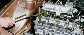
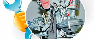
To adjust the valves on a carburetor engine, you will need to remove the air filter housing and disconnect the carburetor throttle actuator. On an injection engine, you just need to disconnect and put aside all interfering pipes and wires. Unscrew the bolts securing the valve cover and remove it.
Next, if the engine is carburetor and equipped with a ratchet, insert the manual engine start handle into it and use it to turn the crankshaft.
On an injection engine, using a special 38mm wrench, turn the crankshaft by the pulley bolt to the top dead center position of the first cylinder. If there is no such key, support the front wheels of the car, turn off the handbrake, use a jack to lift one rear wheel and engage fifth gear.
The wheel will rotate easily on it, and so will the engine crankshaft. While rotating the wheel, set the TDC mark on the crankshaft pulley or on the camshaft gear.
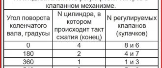
Next, use a 0.15 mm wide feeler gauge to check the gap on closed valves according to the following scheme:
ATTENTION! Thermal clearances are checked on a cold engine!
It is also possible to determine whether the valve is closed or not without a diagram. To do this, you can reach under the kick pedal with your hand and feel the position of the camshaft cam relative to the valve pusher. It should be directed towards him with the back of the head .
When checking the clearance, the feeler gauge should fit between the camshaft and the rocker with slight tension. If the probe passes too easily or, on the contrary, does not pass at all, then this valve must be adjusted.
To do this, hold the adjusting bolt with a 13 wrench (a), release the locknut with a 17 wrench (b) and, rotating it, achieve such a gap so that the dipstick “bites” slightly, but it can be inserted and pulled back out. Having set the gap, hold the adjusting bolt and tighten the locknut.
After adjustment, you need to recheck the gap. We repeat the same operation for all valves.
After successful adjustment, we assemble everything in the reverse order and at this point the valve adjustment can be considered complete.
Thermal gap size
The clearance in the internal combustion engine valves is also set differently, and it also depends on the specific model of the power unit. The value of the thermal gap (GG) is calculated by developers based on the thermal expansion of the metal used in the motor, and manufacturers use different materials for manufacturing. It should also be noted right away that the factory-recommended specifications are not always strictly followed by repairmen, since in practice it turns out that other clearance values are in practice more suitable for a particular engine model, and with them the engine operates in optimal mode.
Technical specifications must be optimal, no more and no less than required. If the gap is too small:
If the gap is too large:
On average, the valve specifications are in the range of 0.15-0.45 mm, and for exhaust, the gaps are always set larger - with small specifications, the exhaust valves are prone to burning out.
Valve adjustment (VA) is usually done when it is cold, but on some models, car manufacturers recommend performing adjustment work on a warm internal combustion engine.
The result of the work done
As a result of correct adjustment of the valve mechanism, engine operation stabilizes, power and traction appear again. A correctly configured gas distribution mechanism stabilizes fuel consumption, because if configured incorrectly, it increases.
If there is no excessive wear in the timing mechanism parts, then, as a rule, excessive noise in the valve cover area disappears. To keep the engine in full working order and its performance within normal limits, this operation must be performed every 10,000-15,000 km.
Valve lid
Owners of the VAZ 2105, like other classic models, often encounter the problem of an oily engine. An unpleasant situation can manifest itself in the form of both small and significant leaks, which indicates failure of the valve cover gasket. Replacing the seal is not a complicated undertaking and will require a minimum of effort and tools, such as:
- flat screwdriver;
- wrench 10;
- ratchet wrench 10.
Replacing the valve cover gasket on a VAZ 2105
We carry out the work of replacing the valve cover seal on the “five” in the following sequence:
- To free access to the cover, remove the air filter and the housing, which is attached to the carburetor.
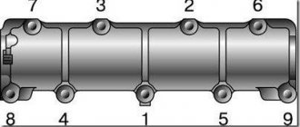
Valve cover tightening procedure
To avoid distortions when installing the valve cover, the nuts must be tightened in a certain order, as can be seen from the figure below.
The appearance of any malfunctions or even their signs associated with wear of the valve seals or the valves themselves should not be ignored. If you replace a failed part or make the necessary adjustments in a timely manner, you will be able to avoid costly engine repairs. Therefore, it is important to monitor the technical condition of the power unit and perform the necessary maintenance according to the manufacturer’s recommendations.
vote
Article rating
Do-it-yourself valve adjustment on a VAZ 2107 with an injector
Owners of VAZ 2107 cars know that these cars are available in both carburetor and injection versions. And if everything is more or less clear with the maintenance of carburetor cars, then questions still arise with the injector on the “sevens”. For example, is it possible to adjust the valves on this machine with your own hands? And if so, how can I make the adjustment correctly? We will try to answer these questions in this article.
What are valves, their role in the operation of internal combustion engines
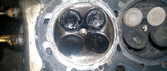
Experienced car enthusiasts can safely skip this part, but for beginners this information will be useful. In order for the engine to work, two valves are needed for each cylinder. Now they are used disc-shaped, with rods. In order for the cylinders to be better filled with the fuel mixture, the diameter of the plate at the inlet valve is larger than that of the exhaust valve. Cast iron or steel are used as materials for the valve seat. The seat is pressed into the cylinder head.
When the engine is running, these parts are subject to severe stress. That is why they are made from alloys that are resistant to thermal and mechanical stress.
A brief excursion into history
The VAZ 2107 was not always fuel-injected. At first, these cars were equipped with conventional carburetors. And the car began to be equipped with a forced fuel injection system only in 2006. The reason is simple: the automaker tried to fit its cars to the standard now known as Euro 2, and this required changing a number of characteristics of the car. The main advantage of replacing the carburetor system with an electronic system was that in the injection version there was no need to fine-tune the injection. That is, there was no “swimming” at idle speed for injection cars. But there were also disadvantages. For example, increased fuel requirements. The catalyst for the injection “sevens” was located directly under the bottom, which means the ground clearance became lower. Repairing such machines was more difficult because it was difficult to get to some parts.
What's the problem with the valves?
The concept of “adjustment” is that a specialist should restore the original clearances of the power unit.
The signal for the need for repairs is a sound - tapping when the engine is running. As a rule, with minor changes in the gap, knocking is present only at the beginning, and then under certain loads. But over time, the condition worsens and the knocking becomes constant. You can miss it at first. But over time, when the noise becomes constant, even an inexperienced driver should not miss it. The problem can be not only an expanded, but also a narrowing of the gap. The balance of the engine is set during assembly so that all the internal combustion power is transferred to the pistons at a certain pressure and speed. The gap (no matter which way it changes) will introduce an imbalance into the operation of the machine, which promises a drop in power under loads necessary for powerful operation.
Reasons for adjustment
Valve system of an injection car VAZ 2107
In general, valve adjustment on the VAZ 2107 should be done every 20 thousand kilometers during scheduled maintenance. But sometimes you have to do this earlier. The reasons are stated below:
- Extraneous noise has appeared in the engine (usually very fast, not too loud clicks).
- Increased fuel consumption is observed in the complete absence of visible leaks.
- In addition, timely adjustment helps prevent premature wear of engine parts.
Tools and preparatory work
To adjust the valves, the Niva must be placed on a level surface. Work can be carried out both in the garage and outdoors; you can drive onto an overpass, but this is not necessary.
Tools and materials
From a special tool, which perhaps not every motorist has, you will need a probe 0.15 mm thick. Its width must be sufficient to be used for adjusting the intake valves. A feeler gauge with a thickness of 0.2 mm is also required. It is used to adjust the exhaust valve.
To work you need to have the following tools and materials:
- Open-end wrenches 17, 13, 8;
- Ratchet (spanner with ratchet and replaceable heads);
- Socket wrenches for 8 and 10;
- Candle key;
- Crankshaft key;
- Screwdriver;
- Rag, rags – clean;
- Brush.
A magnet on a telescopic holder is also useful for detecting and removing fallen fasteners. Almost all the tools - except for keys 13 and 17, as well as probes - are needed for disassembly in order to gain access to adjustable parts.
Preliminary preparation
First of all, you need to disconnect the battery. Next you will need to disconnect the air filter. To do this, you need to disconnect the crankcase gas hose from it. Then they begin to dismantle the filter housing cover by unfastening the four latches.
Now, to remove the cover, all that remains is to unscrew the 10-point nut, which is installed on the stud in the middle of the assembly. The filter housing is held in place with four 8mm nuts; they are easiest to remove with a spanner. Finally, you need to cover the carburetor with a technological cover (you can make it yourself from cardboard or plywood) to prevent dirt from getting inside it.
Next you should disconnect from the carburetor:
- Longitudinal thrust. It is disconnected by removing the mounting bracket from the return spring lever;
- Transverse traction. It is located on the throttle valve drive lever;
- Choke cable;
- Crankcase gas exhaust hose;
- Fuel line.
Continuing disassembly should begin by detaching the brake hose from the vacuum booster. Then the high-voltage wires are disconnected from the spark plugs and ignition coil. Remove the distributor sensor cover together with all wires. The spark plugs are unscrewed. Pull out the oil dipstick.
Gaining access to valves
To begin adjusting the clearances, you need to remove the valve cover. It is held in place by eight 10mm nuts. After tightening them, you need to remove all the brackets and pressure washers.
Scheme and procedure
- First of all, you need to turn off the car engine and let it cool down properly.
- Using a 10mm wrench, unscrew the 8 nuts on the cylinder head cover, then remove the cover. As a result, the valve adjustment screws will become visible.
- Before adjusting the screws, the crankshaft must be set to a certain position. The shaft can be turned with a 38mm key. It should be turned until the mark on its gear aligns with the mark on the cylinder block.
The mark on the shaft gear must match the mark on the cylinder block
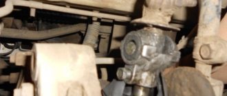
The plunger tensioner nut is loosened with a 13mm wrench
The nut on the valve is loosened with a 17 wrench
How is the procedure performed?
The car must be placed on a flat surface and a tool for turning the crankshaft (ratchet) must be prepared. If this is not the case, then you can get by with a jack. We will turn the crankshaft using muscle force - rotate the wheel in fourth gear.
Before opening the valve cover, you need to tighten the timing chain. All activities related to adjusting any parts of the engine should begin with this.
Loosen the tensioner nut 13 and turn the crankshaft 2-3 turns. After this, tighten the nut. The tension device performed all the necessary manipulations.
Examination
After all the valves have been adjusted, use a 38mm wrench to turn the crankshaft 3-4 full turns and take a control measurement of all clearances using a feeler gauge. If there are no gap violations, you can close the cylinder block cover and try to start the car engine.
Fines for crossing the stop line and speeding will no longer bother you!
Checking valve clearance using a feeler gauge
Video: how to adjust valves on a VAZ 2107 injector with your own hands
Payment
Payment to a Sberbank VISA card The most convenient and profitable payment method for you. Payment can be made through the Sberbank Online system, through a payment terminal (Sberbank ATM), provided that you have a card from this bank. If you are not a client of this bank and you do not have a card, then you can top up your balance at any bank branch through an operator; they will accept cash payment and top up your balance. Commission from 0 to 1%
Cash on delivery (payment upon receipt) Payment for the order will be made at the post office upon receipt of the goods. For cash on delivery services, Russian Post takes an additional commission - approximately 4% of the cost of the order (parcel) upon receipt. In addition to the delivery cost, the post office will also charge you a commission for the cash on delivery service.
Cashless payment This type of payment is suitable for organizations and individual entrepreneurs. An invoice for payment is generated after placing an order. A specialist will contact you to clarify details.
Cash payment You can pay in cash directly in the store, when picking up the goods.
Possible mistakes
If the adjustment is made correctly, extraneous clicks in the motor should disappear. If this does not happen, then something was done wrong. The most common mistake is a violation of the sequence of cylinder adjustments if the work is done with your own hands. It is necessary to set the gap on the injector valves only in the above order and in no other way, there is no need to violate the diagram. If you start with the wrong cylinder, it can completely disrupt the entire timing system, resulting in extraneous noise in the engine that will not go away. And what's more, it can get louder. There is only one way to correct this error: set cylinder 4 to top dead center in accordance with the mark and set everything up again.
Adjusting valves on a VAZ 2107 is not as difficult a task as it seems at first glance. The main thing is to follow the correct sequence of cylinders given above. In addition, you should not be too zealous when tightening the bolts on the cylinder block cover, as the threads there can easily be stripped.
Renovation begins
When the problem is identified, it is possible (and even necessary) to begin repairs. To get to the valve levers themselves, you have to do some preparatory disassembly that will give access to the camshaft.
- The first point for this will be the injector, since this is where both the engine air valve and the protective housing are located, which must be removed, like other belt protection.
- All shields and covers also need to be removed, since it is necessary to work in a comfortable manner, since despite the relative simplicity, the work is still delicate.
The operating scheme will be familiar to all owners of VAZ cars up to version 2107. The adjustment procedure (as well as the operation of the power unit as a whole) is the same for cars in this series. Therefore, there will be no surprises in the repair. The valve numbering order starts from the gear, closer to the camshaft. Repairs need to start from the fourth (the one closest to the car interior).
As for the adjustment itself, it is important to be as careful as possible. You don't need rulers or calipers for this. There are marks everywhere on all parts that have anything to do with the operation of the valves. It is necessary to observe their coincidence. The mark on the crankshaft must match the mark on the protective belt housing. But before this, the TDC 4 valves should be adjusted.
It is better to look at the gaps every 15-20 thousand mileage (at the same time you need to pay attention to the carburetor, cleaning of which also contributes to the stable operation of the car). But since a car is a practical matter, a description alone will not do. Below you can clearly see how the valves are adjusted.
Gap between valve levers and camshaft cams - adjustment
The clearances are adjustable on a cold engine. For adjustment, it is recommended to use a set consisting of a probe of increased width and two open-end wrenches: 13
and
17 mm
. The operation is shown using the example of a carburetor engine.
1. Prepare the car for operations (see “Preparing the car for maintenance and repair”).
2. Remove the cylinder head cover (see “Cylinder head cover gasket - replacement”).
3. Check and, if necessary, adjust the tension of the timing chain (see “Timing chain - tension adjustment”).
4. Remove the ignition distributor cover (see “Ignition timing - checking and adjustment”)
5. Set the camshaft to the BMT position on the compression stroke of the 4th cylinder. To do this, use a special 38 mm
Rotate the crankshaft until the mark on the camshaft sprocket matches the protrusion on the bearing housing.
In this case, the mark on the crankshaft pulley must coincide with the mark on the camshaft drive cover of the carburetor engine.
On an injection engine, the marks have a different shape.
In this position, we adjust the clearances at the intake and exhaust valves of the 4th cylinder (8th cam and 7th cam), as well as the exhaust valve of the 2nd (4th cam) and the intake valve of the 3rd (6th cam) ) cylinders. We count the cams from the camshaft sprocket.
6. Insert a 0.15 mm thick feeler gauge between the lever and the camshaft cam. When the gap is correct, the feeler gauge should enter with slight pinching. Otherwise, we adjust the gap.
7. 17 mm
loosen the locknut of the adjusting bolt.
8. Insert the feeler gauge and use a 13 mm
rotate the adjusting bolt to achieve the required clearance.
9. Take out the dipstick. Hold the adjusting bolt with a wrench and tighten the locknut with a second wrench. Typically, the adjusting bolt rises slightly, reducing the set gap. If necessary, repeat the adjustment.
10. Rotate the crankshaft 360°. In this case, the camshaft and ignition distributor slider will rotate 180°.
11. Similarly, we adjust the clearances at the intake valve of the 2nd cylinder (3rd cam) and the exhaust valve of the 3rd cylinder (5th cam), as well as the intake (2nd cam) and exhaust (1st cam) valves 1st cylinder.
12. Installation of all removed parts is carried out in reverse order.
Preparation
Adjusting the valves of the VAZ-2105 is not the most tricky and difficult task. Of course, when you do any car repairs yourself for the first time, it is always exciting and often very difficult.
But you shouldn’t panic, because VAZ has always made cars for people, the circuits of which can be easily understood on their own (especially if the driver has already dealt with other models in the series).
First of all, you will need to prepare your tools.
- It is necessary to prepare a whole carload of open-end and socket wrenches of various diameters (from 8 to 17).
- In addition, the most important attribute of the work will be the key for working with the shaft. Without it, it will be impossible to correct the operation of the valves.
- Repairs are carried out on any engine condition - cold and warm. It's a matter of urgency and convenience. But in any case, for work you will need a probe with a thickness of 0.15.
- Armed with the necessary tools, you can safely begin diagnostics.
Adjusting valves on VAZ 2107 injector
Adjusting the valves on the VAZ 2107 injector is required for accurate valve timing and is usually done according to plan, that is, approximately every 20 thousand km. mileage But if the characteristic clatter in the engine appeared earlier, then unscheduled adjustment will be required. It’s not difficult to do this yourself, but the performance of the VAZ 2107 engine will depend on the accuracy of all actions.
If the clearances are set correctly, the performance of the cylinders will improve significantly, and the valves themselves will increase their service life and will not require unscheduled adjustments. The amount of oil and fuel consumed will be minimal. Even with the smallest timing repair, valve adjustment is required.
Why is it necessary to adjust the gaps?
This is because during engine operation the thermal gap gradually increases. It is also necessary to adjust these mechanisms after repair.
Now we know what affects correctly set gaps, as well as why and when work needs to be done. Therefore, you can start learning how to adjust the gaps.
It must be said that adjusting the valve clearances will not give any increase in power. However, thanks to correctly set clearances, the engine will operate normally, and there will be no need to change the valve mechanism or the entire piston group. After adjustments, the motor will simply work better. If everything is really bad, previously lost power may be added.
Work order
The VAZ 2107 injector itself is installed on a flat, well-lit area, the ignition is turned off, and the parking brake is applied.
It is recommended that a novice car enthusiast thoroughly understand the structure of the gas distribution mechanism, as well as clarify the location of the thermal gap - the one that requires adjustment.
Adjusting valves VAZ 2107
Before proceeding directly with the adjustment, you need to bring the crankshaft into the desired position. To do this you need to do the following:
- The cover is removed from the cylinder head. To do this, use a 10mm wrench to unscrew 8 nuts. It is recommended to replace the old gasket. After removing the cover, access to the valve adjustment screws opens.
- Then the timing chain tension is checked and, if necessary, the chain should be tightened. The mark on the timing parts is placed at the beginning of the procedure and at the end.
- Remove the cover from the ignition distributor.
- Using a 38 key, the piston of the fourth cylinder is set to the position at top dead center (until the mark on the sprocket and on the cylinder head align). Twisting the crankshaft does not provide for its return - this should be taken into account. Therefore, when twisting, the circle will need to be twisted again. There should be a maximum gap between the cams and levers.
- In this position, the intake and exhaust valves of the fourth cylinder, the exhaust valve of the second cylinder and the intake valve of the third cylinder are adjusted.
- A feeler gauge is inserted between the valve cam and the lever. If the feeler gauge enters with little effort and moves freely, then the gap is normal. If the dipstick fits tightly or, conversely, too loosely, it means that the injector on the VAZ 2107 car engine requires valve adjustment.
If you don’t have a 38 key, the crankshaft can be moved to the desired position in two ways. The first method is quite complicated, it requires a lot of space and some physical effort. It consists in the fact that the VAZ 2107 car is manually pushed until the marks on the sprocket and on the cylinder head coincide.
For the second method, you will need a jack and one assistant. While one person turns the steering wheel, the second will monitor the level of the camshaft and crankshaft.
Some attention should also be paid to the timing chain. You can check its tension with your hands - if the deflection does not exceed 10 mm, the timing belt tension is considered normal.
Purpose and design of the valve mechanism of the VAZ 2101
The operation of an internal combustion engine is impossible without a gas distribution mechanism (GDM), which ensures timely filling of the cylinders with the fuel-air mixture and removes its combustion products. To do this, each cylinder has two valves, the first of which is intended for the intake of the mixture, and the second for the release of exhaust gases. The valves are controlled by camshaft cams.
In each operating cycle, the camshaft cams alternately open the valves
The camshaft is driven by the crankshaft via a chain or belt drive. Thus, the piston system ensures time-distributed intake and exhaust of gases in compliance with the sequence of valve timing. The rounded tips of the camshaft cams press on the rocker arms (levers, rockers), which, in turn, actuate the valve mechanism. Each valve is controlled by its own cam, opening and closing it in strict accordance with the valve timing. The valves are closed using springs.
The valve consists of a rod (rod, neck) and a cap with a flat surface (plate, head) covering the combustion chamber. The rod moves along a sleeve that guides its movement. The entire timing belt is lubricated with engine oil. To prevent lubricant from entering the combustion chambers, oil seals are provided.
Springs, valve stem seals and valves have to be changed periodically
Each valve timing must strictly correspond to the position of the pistons in the cylinders. Therefore, the crankshaft and camshaft are rigidly connected through the drive, with the first shaft rotating exactly twice as fast as the second. The full operating cycle of the engine consists of four phases (cycles):
- Inlet. Moving down in the cylinder, the piston creates a vacuum above itself. At the same time, the intake valve opens and the fuel-air mixture (FA) enters the combustion chamber under low pressure. When the piston reaches bottom dead center (BDC), the intake valve begins to close. During this stroke, the crankshaft rotates 180°.
- Compression. Having reached BDC, the piston changes direction of movement. As it rises, it compresses the fuel assembly and creates high pressure in the cylinder (8.5–11 atm in gasoline engines and 15–16 atm in diesel engines). In this case, the inlet and outlet valves are closed. As a result, the piston reaches top dead center (TDC). In two strokes, the crankshaft made one revolution, that is, it rotated 360°.
- Working progress. A spark ignites the fuel assembly, and under the pressure of the resulting gas, the piston is directed to BDC. During this phase the valves are also closed. Since the beginning of the working cycle, the crankshaft has rotated 540°.
- Release. Having passed BDC, the piston begins to move upward, compressing the gaseous combustion products of the fuel assembly. At the same time, the exhaust valve opens, and under the pressure of the piston, gases are removed from the combustion chamber. In four strokes, the crankshaft made two revolutions (rotated 720°).
The gear ratio between the crankshaft and camshaft is 2:1. Therefore, during the operating cycle the camshaft makes one full revolution.
The timing belts of modern engines differ in the following parameters:
- upper or lower location of the camshaft;
- number of camshafts - one (SOHC) or two (DOHC) shafts;
- number of valves in one cylinder (from 2 to 5);
- type of drive from the crankshaft to the camshaft (toothed belt, chain or gear).
The first carburetor engine of VAZ models produced from 1970 to 1980 has four cylinders with a total volume of 1.2 liters and a power of 60 hp. With. and is a classic in-line four-stroke power unit. Its valve train consists of eight valves (two for each cylinder). Unpretentiousness and reliability in operation allows it to use AI-76 gasoline.
Video: operation of the gas distribution mechanism
Gas distribution mechanism VAZ 2101
The gas distribution mechanism of the VAZ 2101 is driven by the crankshaft, and the camshaft is responsible for the operation of the valves.
Gas distribution mechanism VAZ 2101: 1 - crankshaft; 2 — crankshaft sprocket; 3 - drive chain; 4 — tensioner bushing; 5 — tensioner adjustment unit; 6 — camshaft sprocket; 7 - camshaft; 8 — valve rocker (lever); 9 - valve; 10 — bushing for the adjusting bolt; 11 — adjusting bolt; 12 — chain damper; 13 - sprocket that controls the operation of the breaker - ignition distributor and oil pump
The torque from the engine crankshaft (1) through the drive sprocket (2), chain (3) and driven sprocket (6) is transmitted to the camshaft (7), located in the cylinder head (cylinder head). The camshaft lobes periodically act on the drive arms or rockers (8), driving the valves (9). Thermal clearances of the valves are set by adjusting bolts (11) located in the bushings (10). Reliable operation of the chain drive is ensured by the bushing (4) and the adjusting unit (5), the tensioner, and the damper (12).
The power strokes in the cylinders of the VAZ 2101 engine have a certain sequence.
The working strokes in the VAZ 2101 cylinders have a certain sequence: numbers indicate the stroke numbers, arrows indicate the direction of movement of the pistons in the cylinders
Adjustment process
Adjusting the valves on a VAZ 2107 injector car occurs as follows:
- Using a 17 wrench, loosen the tightening of the adjusting bolt.
- The feeler gauge is inserted into the gap between the lever and the valve cam.
- The required gap is set by adjusting the height with a 13 key.
- After the required clearance has been set, the locknut should be tightened, not forgetting to keep the adjusting bolt from turning. After this, the gap is checked (the feeler gauge should enter with little effort) and, if necessary, adjusted again.
- The intake valve of the second cylinder and the exhaust valve of the third cylinder (cams 3 and 5, respectively), as well as the second exhaust and intake valve of the first cylinder (cams 1 and 2, respectively) are adjusted after turning the crankshaft 360 degrees.
The absence of a characteristic clattering sound in the engine compartment indicates that the work has been carried out efficiently.
About choosing styli
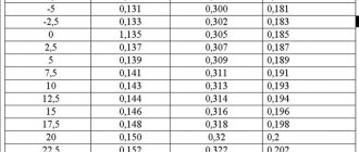
Uneven knocking noises in the area of the upper part of the valve cover indicate increased clearances. According to the instructions for setting the VAZ-2106 valves, they can be adjusted. The gaps are changed using special feeler gauges for classic VAZ models. These probes are wide. The standard set of feeler gauges is narrow and cannot cover the entire width of the gap in the operating area of the pressure levers and camshaft cams. This will not allow you to accurately determine whether the gap is correct. On the case in which the dipstick is sold, there is a diagram for adjusting the valves in the form of a convenient table.
Special tools and accessories
1. Rolling hydraulic jack. A standard car jack is often either inconvenient or simply useless when performing some jobs.
2. Stand (support) for the car,
adjustable in height and with a permissible load of at least 1 ton. It is advisable to have four such stands.
3. Wheel chocks
(at least 2 pieces).
4. Double-sided wrenches for brake system fittings 8, 10
and 13 mm.
The two most common types of these wrenches are the clamp wrench and the slotted socket wrench. The clamping wrench allows you to unscrew fittings with worn edges. To put the wrench on the brake pipe fitting, you need to unscrew the pinch bolt. A socket wrench with a slot allows you to do the job more quickly, but such a wrench must be made of high-quality steel with appropriate heat treatment.
5. Special forceps
for removing retaining rings. There are two types of such pliers: sliding - for removing retaining rings from holes and sliding - for removing retaining rings from shafts, axles, and rods. The tongs also come with straight and curved jaws.
6. Oil filter puller.
7. Universal two-jaw puller for removing pulleys, hubs, gears.
8. Universal three-jaw pullers
for removing pulleys, hubs, gears.
9. Universal joint remover.
10. Puller and mandrel for replacing valve stem seals.
11. Desiccant for disassembling the valve mechanism of the cylinder head.
12. Tool for removing ball joints.
13. Device for removing the piston pin.
14. Device for pressing out and pressing in silent blocks of front suspension arms.
15. Tool for removing steering rods.
16. Crankshaft ratchet key.
17. Spring remover.
18. Impact screwdriver with a set of attachments.
19. Digital multimeter for checking the parameters of electrical circuits.
20. Special probe or 12 V test lamp
to check electrical circuits of the vehicle that are under voltage.
21. Pressure gauge
to check tire pressure (if there is no pressure gauge on the tire pump).
22. A device for adjusting clearances in valve actuators.
23. Compression gauge for checking the pressure in the engine cylinders.
24. Bore gauge for measuring the diameter of cylinders.
25. Vernier caliper with depth gauge.
26. Micrometers with a measurement limit of 25-50 mm and 50-75 mm.
27. Set of round probes
to check the gap between the spark plug electrodes. You can use a combination key to service the ignition system with a set of necessary probes. The key has special slots for bending the side electrode of the spark plug.
28. Set of flat styli
for measuring gaps when assessing the technical condition of units.
29. Wide probe 0.15 mm
to check valve clearances.
30. Mandrel
for centering the clutch driven disc.
31. A mandrel for crimping piston rings when installing the piston into the cylinder.
32. A hydrometer for measuring the density of a liquid (electrolyte in a battery or antifreeze in an expansion tank).
33. Special device with metal brushes
for cleaning battery wire terminals and terminals.
34. Oil syringe
for filling oil into the gearbox and rear axle.
35. Pressure syringe
for lubricating the driveshaft splines.
36. Hose with bulb for pumping fuel.
The hose can be used to remove fuel from the tank before removing it.
37. Medical syringe or bulb
for sampling fluids (for example, if it is necessary to remove the master cylinder reservoir without draining all the brake fluid from the system). The syringe is also indispensable for cleaning carburetor parts.
When performing the work, you may also need: a technical hair dryer (heat gun), an electric drill with a set of metal drills, a clamp, tweezers, an awl, a tape measure, a wide bench ruler, a household steelyard, wide containers for draining oil and coolant with a volume of at least 10 liters.