Since the beginning of car production, as the design improved, the following types of carburetors were installed: instead of the 2101-1107010 carburetor, from 1974 they began to install 2101-1107010-02; since 1977 - 2.101-1107010-03; and since 1979, Ozone carburetors 2105-1107010-20 have been installed on VAZ-2101, -21011, -21013, -2102, -21021 cars along with new ignition distributors with a vacuum ignition timing regulator. With old ignition distributors (without a vacuum regulator), a carburetor 2105-1107010-10 is installed, which is supplied as spare parts and differs from 2105-1107010-20 mainly in the absence of a vacuum selection for the vacuum regulator.
Carburetors with corresponding ignition distributors are interchangeable with each other. Basic data are given in table. 3.
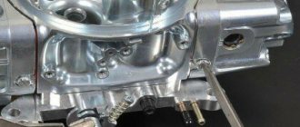
Carburetor 2105-1107010-20
Emulsion type, two-chamber, with falling flow (Fig. 32). It has a balanced float chamber, main metering systems, an enrichment device (econostat), an idle system, a transition system, a diaphragm starting device, a spool valve for crankcase gas suction, and a pneumatic drive for the secondary chamber throttle valve.
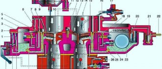
Rice. 32. Carburetor 2105-1107010-20:
1 - air damper; 2 — diaphragm trigger; 3 — three-arm lever; 4 — telescopic rod; 5 — throttle drive lever of the first chamber; 6 - lever that limits the opening of the throttle valve of the secondary chamber; 7 — return spring; 8 - rod connecting the throttle valve of the primary chamber with a three-arm lever; 9 — pneumatic drive rod; 10 — pneumatic drive of the throttle valve of the secondary chamber.
Correct selection
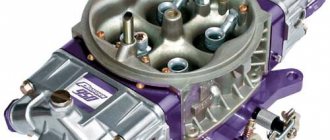
Fans of tuning VAZ classics and simply wanting to improve its performance characteristics most often opt for Solex
.
Initially, models from front-wheel drive cars DAAZ 2108 and 21083
. It is impossible to install them on classics without minor modifications. Let's look at such works in more detail.
When choosing a device for your car, you need to take into account the engine displacement. For engines with a volume of 1.3 liters, the DAAZ 2108 fits well, and for 1.6 - the DAAZ 21083. These devices differ in the diameters of the cross-sections of the diffusers, as well as the fuel and air nozzles. To install any of these models on a classic engine, you must additionally prepare the following components. A new set of gaskets for the carburetor, a piece of hose to ensure its heating, a tee to the fuel system, a valve and a set of rods for the gas pedal.
To get the most out of this idea, it would be advisable to replace the ignition system with an electronic one. Now let's look at the procedure for installing the carburetor:
- On a cold engine, you need to remove the standard device along with the gaskets;
- The next step is to install new gaskets. The first is paronite, then plastic and then cardboard on top;
- A new Solex is placed on top of these gaskets, but the fasteners are not yet clamped;
- Under the nuts closest to the engine on the carburetor, place a bracket from a set of rods for the gas pedal;
- The double-arm pedal drive lever, which is removed from the valve cover, should be placed on the bracket;
- The rod on it, the one that is shorter, is replaced with a new one from the purchased kit, and if necessary, the length is adjusted;
- The pedal return spring should be placed closer to it;
- Now you need to ensure heating of the device; to do this, connect it to the outlet pipe on the intake manifold.
Main dosing systems
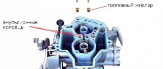
Designed to prepare a combustible mixture of the required composition in throttling modes (low and medium engine loads). Fuel enters float chamber 4 through needle valve 28 (Fig. 33). Float 32 maintains the required fuel level. From the float chamber, fuel through the main fuel jets 34 and 45 enters the emulsion wells, mixes with the air leaving the holes of the emulsion tubes 35, 44 and entering them through the main air jets 9 and 19. Then, through the spray nozzles 12, the emulsion enters the small and large carburetor diffusers.
Rice. 33. Carburetor diagram:
1 — accelerator pump lever; 2 - adjusting screw; 3 - plug; 4 - float chamber; 5 — fuel jet of the transition system; 6 — econostat air jet; 7 — air jet of the transition system; 8 — econostat fuel jet; 9 — main air jet of the secondary chamber; 10 — econostat emulsion jet; 11 — econostat sprayer; 12 — sprayer of the main dosing system of the secondary chamber; 13 — small diffuser of the secondary chamber; 14 — valve-screw of the accelerator pump; 15 — accelerator pump nozzle; 16 — small diffuser of the primary chamber; 17 — air damper; 18 — adapter bushings; 19 — main air jet of the primary chamber; 20 - starter jet; 21 — drive rod of the starting device; 22 — starting device housing; 23 - rod; 24 — diaphragm of the starting device; 25 — adjusting screw of the starting device; 26 — idle air jet; 27 — needle valve seat; 28 — needle valve; 29 — filter; 30 — bracket with stop; 31 — damper ball; 32 — float; 33 — idle fuel jet; 34 — main fuel jet of the primary chamber; 35 — emulsion tube of the primary chamber; 36 — mixture quality adjusting screw; 37 — adjusting screw for the amount of mixture; 38 — mixing sleeve; 39 — throttle valve of the primary chamber; 40 - primary mixing chamber; 41 - secondary mixing chamber; 42 — throttle valve of the secondary chamber; 43 - non-adjustable holes of the transition system; 44 — emulsion tube of the secondary chamber; 45 — main fuel jet of the secondary chamber; 46 — accelerator pump check valve; 47 — accelerator pump bypass jet; 48 — accelerator pump diaphragm.
The main fuel jets are 34 and have a marking stamped on the side of the head (for example, 107 or 162), which indicates the diameter of the jet opening (1.07 or 1.62 mm). The main air jets 9 to 19 are marked on the upper plane (for example, 170 or 190) and also indicate the diameter of the jet holes (1.70 or 1.90 mm). A marking is applied to the cylindrical surface of the emulsion tubes 35 and 44, which indicates the calibration number of the tube (for example, 15). Small diffusers 13, 16 also have markings (for example, 3.5 and 4.5), indicating the calibration number of the atomizer hole 12.
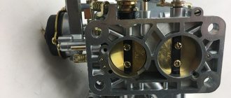
Single chamber weber carburetor
Single chamber Weber carburetor or SURPRISES OF A LONELY CHAMBER
Is a single-chamber Weber carburetor capable of replacing the domestic DAAZ?
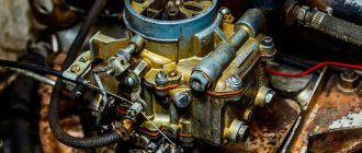
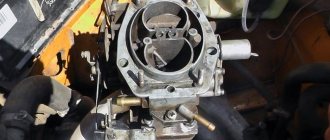
Which device causes the most trouble to the owner of a domestic car? Of course, the carburetor. the vagaries of Solex and Ozone carburetors , and their repair is still one of the most pressing topics in garage disputes and conversations in the smoking room. Is it possible to end the torment in one fell swoop, so as to forget once and for all about purging channels, forced idle valves, jerks and failures?
Unfortunately, in our country, fuel injection systems will not completely replace carburetors any time soon. But now it is possible to replace a domestic device with an imported one - Weber carburetors for VAZ cars have appeared in spare parts stores. And not the beloved two-chamber model that was installed on the first Lada cars. The current Weber-32ICE/55T 251 is a simple single-chamber carburetor with a falling flow without any complex additional systems. Two modifications go on sale: for “classics” and for front-wheel drive Samaras. They differ from each other only in a set of adapter parts for installation, made in Italy. Well, let's compare the primitive-looking Weber with the most modern domestic carburetor DAAZ-21083, which is produced under license. THEY ARE GOING TO THE START.
Three carburetors took part in the comparison test. "Weber-32ICE" is provided by the supplier company - "Italian Trade Organization". At the warehouse, we took the first box with a carburetor we came across. Before testing began, the device was not opened or adjusted. Since the high quality of the product is guaranteed, there is nothing to control the compliance of a specific sample with factory data. From the accompanying documentation it follows that Weber received a certificate of conformity from Gosstandart and complies with UNECE standards No. 83 and GOST 17.2.2.03-87. In addition, the device meets the German TÜV requirements, and the toxicity does not exceed the permissible limit for vehicles using leaded gasoline.
The standard DAAZ-21083 was removed from a new car (mileage 200 km). We didn’t risk buying the device from a spare parts store - there are too many outright defects there. Before the test, we removed the cover, checked the fuel level in the float chamber, the correspondence of the jets to the nominal value, and the operability of most systems. The Russian Solex must also be in good working order and adjusted to factory specifications - this is the requirement for the purity of the experiment. The third participant in the test is the same DAAZ, but with changed adjustments (they are most often used by craftsmen to improve the driving characteristics of the car). Instead of the air jet of the first chamber marked “165”, “155” was installed, and the fuel jet of the second chamber “97.5” was replaced with “100”. Both non-standard jets are factory ones - they are used in the 21083-31 carburetor with an automatic starter. In addition, the accelerator pump nozzle was replaced with a Nivovsky one (from a DAAZ-21073 carburetor) - with a nozzle directed only into the first chamber. You will find the main parameters of all three devices in the table. 1.
The “carrier” of the experimental carburetors was a completely serviceable VAZ 21093 car with a 1500 cm3 engine, a 3.9 main pair and Barum OR-42 tires with a size of 175/70R13. With a tire pressure of 2 kgf/cm2, the run-out of the “nine” from a speed of 50 km/h was 576 m. Driving tests took place on special roads at the NITSIAMT test site using the professional Datron measuring complex for measurements. Movement in a conventional urban cycle was simulated in the laboratory on running drums. WHAT THE NUMBERS SAID First, let's look at the results of laboratory studies (Table 2). No miracles happened with fuel consumption in the conventional urban cycle. The most economical is the standard Solex, the modified one is slightly behind, the outsider is the single-chamber Weber. But there is one caveat. All three carburetors were “run in” using the same method, without taking into account the features of each device - this is how comparative tests are carried out. But in the hustle and bustle of the city, consumption greatly depends on driving style, the ability to use the advantages of a particular carburetor and a host of external factors. This means that you can get different numbers and the picture will change. Although, of course, due to its design features, “Weber” still won’t make it to the top. As for the toxicity of exhaust gases, formally all devices met the requirements of GOST and UNECE. Moreover, most indicators do not differ much. But the Weber’s CO content at high speeds is at its limit, while both Solexes have a substantial reserve. What's the matter? Additional research showed that not all Italian carburetors tend to “smoke” so much. We managed to get to the bottom of the reason (the tolerances in the manufacture of jets are large) and gave the supplier the appropriate recommendations. Road tests, during which the car's acceleration dynamics, engine elasticity (Table 3) and fuel efficiency (Fig. 1) were assessed, were downright a triumph for the modified Solex: it was ahead of its competitors in almost all respects. But let us remember that, compared to the standard DAAZ-21083, the converted one consumes more fuel in the conventional urban cycle, and is also, at least slightly, still inferior in terms of exhaust toxicity. There are other “buts”, which will be discussed below. In the meantime, let's compare the regular DAAZ with the Weber. The maximum speed is higher with a domestic carburetor. When accelerating from zero to 100 km/h with a difference of more than a second, the Solex wins again. But take a look at the acceleration curves (Figure 2). Up to a speed of 80 km/h, the carburetors, as they say, go neck and neck, and only then the Weber begins to lag noticeably behind. There's nothing to be done - he really misses it. second camera. What about elasticity? With the standard test method in IV and V gears, the picture is repeated. At first, Weber keeps pace with DAAZ, then lags behind. Now let’s complicate the task: acceleration in the same gears, but from a minimum speed, when the speed is below 1000 rpm and the car is moving “pull” (Fig. 3 and 4). What a trick! “Weber”, it turns out, has excellent “lower end” - the engine with it has a lot of torque. In fourth gear, the Solex is ahead until the car reaches 100, and in fifth - 120 km/h. Then the DAAZ takes its toll - at high speeds the two-chamber is noticeably more lively. During this exercise, the “Italian” received flattering evaluations from experts. When we tried to accelerate at low speed with the Solex, the car jerked every now and then, but with the Weber it pulled surprisingly smoothly. Now let's look at the fuel-speed characteristics (see Fig. 1). Using them, you can estimate gasoline consumption when driving in fifth gear at a steady speed. In its very driving range - from 65 to 105 km/h - the Weber is more economical than the DAAZ, and from 80 to 100 km/h it is barely inferior to the modified Solex. And this property of the “Italian” must be used. Do Samara owners often engage fifth gear when they barely reach 70 km/h? Of course not: the car can barely pull and even a gentle hill will require you to switch to a lower gear. And “Weber” behaves well in such a situation and even allows you to accelerate without switching. LET'S TURN AWAY FROM INSTRUMENTS Carburetors have passed a whole range of tests. The car drove in a circle with a diameter of 25 m at speeds of 20, 30, 40 and 50 km/h, overcame cascades of turns of varying steepness on the mountain road of the test site, climbed 30- and 40-percent slopes and descended from them, stopped in the middle of the slide and worked at idle, rolled downhill for a long time at forced idle with the gear engaged, but the gas pedal fully released. All three devices passed the tests perfectly - there were no malfunctions. Even the Weber, which, unlike the Solex, does not have twin floats immersed in narrow wells, was not, contrary to expectations, bothered by the ebb or flow of gasoline in the float chamber.
Econostat
Enriches the fuel mixture at maximum engine speeds and is included in the secondary chamber. Fuel from float chamber 4 (see Fig. 33) through fuel jet 8 of the econostat enters the channels located in the carburetor cover, where air from jet 6 is mixed.
The fuel-air emulsion passes through the channel through the emulsion nozzle 10 and enters through the atomizer 11 into the diffuser. The econostat comes into operation at speeds close to maximum, with the throttle valves fully open.
Repair instructions
As a rule, carburetor adjustment is required after 7500–8000 km. If the car is not used much, then this work should be carried out at least once a year. Before tuning, thoroughly clean the spark plugs, distributor and check the wiring.
List of tools and preparatory work
Adjustment does not require much physical strength, the main thing is to do everything accurately and accurately. Preparing the tool:
- set of wrenches;
- flat and Phillips screwdrivers;
- rags;
- latex gloves;
- toothpicks;
- solvent;
- pump or can of compressed air.
The first step is to remove the top cover, float and vacuum valve from the carburetor.
After unscrewing the 4 nuts, remove the top cover of the carburetor and clean the chambers
The internal chambers must be thoroughly cleaned of dust and soot residues. We clean small holes with air using a spray can or a regular pump. Warm up the engine and set it to the handbrake.
How to adjust: step-by-step instructions
- We tighten the two diffuser quality screws until they stop.
Screw 1 adjusts the amount of gasoline supplied, screw 2 adjusts the throttle position - Loosen the screws 2 turns and start the engine.
- Smoothly tighten the quality screw and the diffuser quantity screw. The first of them regulates the amount of fuel, and the second opens the throttle valve. Thus, we reduce the supply of fuel and air to the cylinders.
- We carry out a similar operation with each quality screw.
Idle system
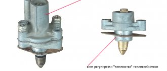
Prepares a rich hot mixture while the engine is idling. Fuel from the emulsion well enters the idle jet 33 (see Fig. 33) and is mixed with air entering through the air jet 26. Then, in the form of an emulsion, it passes through the emulsion channel and exits through the holes into the throttle space. The emulsion output is regulated by screw 37 for the quantity of the mixture and screw 36 for the quality of the mixture. The outlet hole above the screws ensures that there are no “dips” in engine operation when the throttle valve is opened. To prevent violation of the factory idle speed adjustment, plastic limiting bushings are pressed onto screws 36, 37, allowing the adjusting screws to be turned only half a turn. Blue bushings are installed at the factory, and red bushings are installed at service stations.
Symptoms that clearly indicate a faulty pump and rod
Fuel pump and gasket set
The main sign of a faulty fuel pump is that the engine begins to stall at high temperatures, and after stopping it does not start. It sits for a while, cools down, and only then is it possible to start the engine. Of course, another breakdown has a similar symptom - a violation of valve adjustment. Only in this case does it feel as if the engine is trying with all its might to pull the car, but cannot, it is beyond its capabilities. And when the fuel pump starts to malfunction, the engine simply stalls.
The reason for this is excessive heating. As we said, the VAZ 2101 fuel pump consists of two valves. Well, one or both became warped due to heating and stopped opening. Cool them slightly and you can continue moving. Remember how often you saw a wet rag thrown over a gas pump? Now you know what purpose this is for.
But there is also a VAZ 2101 fuel pump rod, a truly wonderful contraption. It is made of steel. And if in the Soviet years it was hardened, now no one needs it. The price of the stock is at least 25 rubles. Well, who will spend kilowatts of energy on a part whose final cost is 25 rubles? Nobody! What happens then? But an unpleasant picture emerges - the fuel pump lever simply erases the rod, reducing its length.
And if you have gaskets under the fuel pump housing, then you are just lucky! When you pull one out, the rod will protrude from the insert more. And that’s it, the pump will continue to pump gasoline normally. But what if there are no gaskets? Who knows what could happen, for example, they forgot to put them on? And that’s why the rod was worn out. What to do then? Try taking it out and inserting it the other way. You know, this action helped several times.
A sign that the fuel pump rod has worn out is that the car accelerates to a certain speed. I had such a thing that I drove around the city normally, but as soon as I got on the highway, my maximum speed was 90 km/h, and that’s all. You step on the gas, but the engine stalls, it doesn’t have enough gasoline. I released the pedal a little - it drives calmly and shows no signs of breakdown. Moreover, a pump rod malfunction cannot always be detected when driving around the city or at idle speed. A short-term increase in engine speed will not give the same effect as long-term driving at high speed.
Transition system
Ensures the absence of “dips” in engine operation at the beginning of the opening of the throttle valve of the secondary chamber and enriches the combustible mixture at maximum speed of the engine (throttle valves are open). Under the influence of vacuum at the outlet holes 43 (see Fig. 33), fuel from the emulsion well through the fuel channel, fuel nozzle 5 of the transition system, mixing with air from nozzle 7, enters the throttle space through the channel through the holes. On the cylindrical belt of the jet 5 there is a marking indicating the diameter of the jet hole.
Acceleration pump
Enriches the fuel mixture when the throttle valve is opened sharply, ensuring good vehicle response. When the throttle valve 39 is sharply opened (see Fig. 33), the cam on the valve axis presses lever 1 and acts through the pusher on the diaphragm 48, overcoming the resistance of the return spring. The diaphragm supplies fuel through the channel and injects it through the atomizer 15 into the primary mixing chamber. Part of the fuel is passed through the bypass jet 47 back into the float chamber. The bypass jet is selected in such a way that when the throttle valve is opened smoothly, all the fuel is bypassed into the float chamber. The cam profile allows for dual injection. The second injection coincides with the beginning of the opening of the throttle valve of the secondary chamber.
The sprayer 12 has a marking (for example, 40) indicating the diameter of the sprayer opening (0.40 mm).
Starting device
Ensures cold engine starting. It consists of an air damper 2 (Fig. 34) above the primary mixing chamber, a three-arm lever 1, a telescopic rod, a throttle valve drive rod 7 and a diaphragm device. Lever 1 is connected by a rod to the manual control button in the cabin under the instrument panel. When the button is pulled, the three-arm lever through rod 7 slightly opens the throttle valve of the primary chamber, and the telescopic rod, by turning the air damper lever, closes the air damper. Rod 3, connected to the air damper lever, moves along the groove of the rod 4 and occupies the extreme left position.
Where is the fuel pump located on 2106, 2107 and other models
The location of the fuel pump on carburetor and injection classic VAZs is different. In the first, it is installed on the left (as viewed from the passenger compartment) on the engine cylinder block on a special boss, and is attached to it using studs through a heat-dissipating ebonite spacer. The mechanical fuel pump is driven from the engine intermediate shaft through an eccentric and a pusher (rod).
The mechanical fuel pump on the classic is mounted on a special boss on the engine cylinder block
In injection Zhiguli cars, the pump is included in the design of the fuel module. It is located inside the gas tank. The design of an electric pump consists of a DC electric motor and a specially shaped impeller mounted on its shaft. The electric motor is powered from the vehicle's on-board network. The electrical circuit of the device is protected by a separate fuse and relay.
The electric fuel pump on injection classic models is installed in the gas tank
Pneumatic drive of the throttle valve of the secondary chamber
Designed to smoothly turn on the main metering system of the secondary chamber (Fig. 35) and eliminate the need for strong enrichment of the combustible mixture compared to carburetors with sequential opening of the throttle valves. The pneumatic drive automatically adjusts the position of the damper depending on the speed of the engine.
Rice. 35. Pneumatic drive of the throttle valve of the secondary chamber of carburetors 2105-1107010-20 and 2105-1107010-10:
1 — pneumatic drive jet located in the diffuser of the primary chamber; 2 — throttle valve drive lever; 3 - lever rigidly connected to the axis of the throttle valve of the primary chamber; 4 - lever that limits the opening of the throttle valve of the secondary chamber; 5 — pneumatic drive jet located in the diffuser of the secondary mixing chamber; 6 - lever connected to lever 9 through a spring; 7 — axis of the throttle valve of the secondary chamber; 8 — pneumatic drive rod; 9 — throttle control lever of the secondary chamber; 10 — channel for supplying vacuum to the pneumatic drive; 11 — rod bushing; 12 - working cavity of the pneumatic drive.
When the throttle valve of the first chamber is open, as the load on the vehicle increases, the crankshaft rotation speed and, consequently, the vacuum in the mixing chambers decrease, and the secondary chamber valve closes. The main air flow will pass through the primary mixing chamber, improving fuel atomization. When the throttle valve control pedal of the primary chamber is sharply lowered, the primary chamber flap closes and lever 4 forcibly closes the secondary chamber throttle valve, preventing an increase in the crankshaft speed. The possibility of self-oscillation of the pneumatic drive mechanism is eliminated by connecting cavity 12 with diffusers of both the secondary and primary mixing chambers through jets 1 and 5.
Main overall dimensions of the VAZ21011 car
- Repair manuals
- Repair manual for VAZ 2101 (Zhiguli) 1970-1985.
- Main overall dimensions of the VAZ-21011 car
↓ Comments ↓
1. Technical data 1.0 Technical data 1.1 Main overall dimensions of the VAZ-2101 car 1.2 Main overall dimensions of the VAZ-21011 car 1.3 Main overall dimensions of the VAZ-2102 car 1.4 Technical characteristics of cars 1.5 Controls and monitoring devices 1.6 Ignition switch 1.7 Ventilation and heating controls interior 2. Operation and maintenance 2.0 Operation and maintenance 2.1. Vehicle operation 2.2. Vehicle maintenance
3. Engine 3.0 Engine 3.1 Features of the device 3.2 Possible engine malfunctions, their causes and methods of elimination 3.3 Removal and installation of the engine 3.4 Disassembly of the engine 3.5 Assembly of the engine 3.6 Bench tests of the engine 3.7 Checking the engine on the car 3.8. Cylinder block 3.9. Pistons and connecting rods 3.10. Crankshaft and flywheel 3.11. Cylinder head and valve mechanism 3.12. Camshaft and its drive 3.13. Cooling system 3.14. Lubrication system
4. Fuel system 4.0 Fuel system 4.1. Power system 4.2. Carburetor
5. Ignition system 5.0 Ignition system 5.1 Setting the ignition timing 5.2 Gap between the breaker contacts in the ignition distributor 5.3. Checking ignition devices on a stand 5.4 Possible ignition malfunctions, their causes and methods of elimination
6. Starting and charging system 6.0 Starting and charging system 6.1. Battery 6.2. Generator 6.3. Starter
7. Transmission 7.0 Transmission 7.1. Clutch 7.2. Gearbox 7.3. Cardan transmission 7.4. Rear axle
8. Chassis 8.0 Chassis 8.1. Front suspension 8.2. Rear suspension 8.3. Shock absorbers 8.4 Possible malfunctions of the chassis, their causes and methods of elimination
9. Steering 9.0 Steering 9.1 Features of the device 9.2. Inspection, check and adjustment of steering 9.3. Steering mechanism 9.4. Steering rods and ball joints 9.5. Pendulum arm bracket 9.6 Possible steering malfunctions
10. Brake system 10.0 Brake system 10.1. Features of the device 10.2. Checking and adjusting brakes 10.3. Clutch and brake pedal bracket 10.4. Main cylinder 10.5. Front brakes 10.6. Rear brakes 10.7. Rear brake pressure regulator 10.8. Parking brake 10.9 Possible brake malfunctions, their causes and methods of elimination
11. Electrical equipment 11.0 Electrical equipment 11.1. Electrical circuit diagrams 11.2. Lighting and light signaling 11.3. Sound signals 11.4. Windshield wiper 11.5. Heater electric motor 11.6. Control devices
12. Body 12.0 Body 12.1 Features of the device 12.2. Repair of the body frame 12.3. Paint and varnish coatings 12.4. Anti-corrosion protection of the body 12.5. Doors 12.6. Hood, trunk lid, bumpers 12.7. Body glazing and windshield washer 12.8 Instrument panel 12.8. Removal and installation 12.9. Seats 12.10. Heater
13. Features of repair 13.0 Features of repair 13.1. Car VAZ-21011 13.2 Cars VAZ-21013 13.3. Car VAZ-2102 13.4 Cars VAZ-21021 and VAZ-21023
14. Appendices 14.0 Appendices 14.1 Tightening torques for threaded connections 14.2 Tools for vehicle repair and maintenance 14.3 Used fuels, lubricants and operating fluids 14.4 Basic data for adjustments and control
Carburetor control drive
The throttle valve opens from the pedal 9 (Fig. 36), which is mounted on the lever of the roller 12. The roller is mounted pivotally in two brackets 13, which are mounted on the front panel of the body. Levers are welded to the shaft and the action from lever 14 is transmitted to the longitudinal link 2, the intermediate link 15, the transverse link 1 and then to the throttle valve drive lever. Rods and 2 have plastic adjustable ends.
Rice. 36. Carburetor control drive:
1 - transverse thrust; 2 - longitudinal thrust; 3 — rod fastening bracket; 4 — air damper control cable; 5 and 7 - seals; 6 — cable handle; 8 — lock washer; 9 — throttle valve control pedal; 10 — return spring; 11 — lever; 12 - roller; 13 — bracket for mounting the roller; 14 — lever; 15 — intermediate lever; 16 — return spring fastening screw; 17 — return spring.
The air damper is controlled by button 6, which is connected by rod 4 to the air damper drive lever. The rod shell is mounted on the cover of the pneumatic drive of the secondary chamber throttle valve. When the button is fully extended, the air damper should be completely closed, and when it is recessed, it should be completely open.
About replacing the air filter
Many car enthusiasts, especially beginners who bought a used car, often take the time to look into the air filter housing and are in no hurry to change it. But this must be done every 20 thousand kilometers. Otherwise, the air filter, especially heavily soiled in the summer, can significantly reduce engine power. Carburetor repair will be inevitable if a dirty filter is systematically used. Therefore, it is a good idea to remove the air filter every 5-10 thousand kilometers and visually, “by eye,” determine the degree of contamination.
Pay attention to the bottom edge of the air filter during inspection, and to its inner surface. If it is heavily oiled, this indicates a malfunction of the oil scraper rings, or severe wear of the piston group
In this case, it is necessary to repair the cylinder block or replace the rings.
Carburetors 2101-1107010 and 2101-1107010-02
They differ from 2105-1107010-20, as well as from each other in jet diameters. Carburetors with sequential throttle valves have a float chamber unbalance valve and a heated throttle body.
The float chamber unbalance valve makes it easier to start a hot engine by preventing fuel vapor from entering the engine inlet tract, which can lead to an excessively rich mixture and, therefore, difficult starting. When the throttle valves are closed, the float chamber is connected to the atmosphere through a valve. When the throttle valve is turned, the valve drive lever is released, and the valve, closing, separates the float chamber from the atmosphere.
Adjustment of valves
If knocking, unstable operation, or increased vibration occur, you should pay attention to the valves. If the valve timing of the gas distribution mechanism is disrupted, they do not operate accurately, that is, the full volume of gas does not enter the working area of the cylinders, complete combustion of the fuel-air mixture in the working chamber does not occur, and the cylinders are not purged
This is all accompanied by the appearance of a shock load on the camshaft cams on the drive lever and the shaft rod. Fuel and engine oil consumption also increases. What happens if you drive with unadjusted valves? Answer: rapid wear of engine parts, increased cost and repair time
If the valve timing of the gas distribution mechanism is disrupted, they do not operate accurately, that is, the full volume of gas does not enter the working area of the cylinders, complete combustion of the fuel-air mixture in the working chamber does not occur, and the cylinders are not purged. This is all accompanied by the appearance of a shock load on the camshaft cams on the drive lever and the shaft rod. Fuel and engine oil consumption also increases. What happens if you drive with unadjusted valves? Answer: rapid wear of engine parts, increasing cost and repair time.
The greatest danger to a car engine is a gap that is less than permissible. Too little clearance between the drive lever and the camshaft cam prevents the valve head from sitting tightly in its seat on the cylinder heads. Through a valve that is not seated, gases from the burnt fuel-air mixture are knocked out of the combustion chamber. Because of this, the exhaust valve cap around the perimeter begins to burn.
Rubber oil deflectors, also known as oil deflectors, also burn out due to a burnt valve cap, which leads to increased engine oil consumption. If the wear of engine parts is large, then it may be better and easier to do an engine swap with your own hands or at a service station.
Even if your engine does not have a belt drive, but a chain drive, then if you do not change the chain before its service life expires, the valves will bend on the piston, as, for example, in the sr20det engine manufactured by Nissan.
Carburetor VAZ 2101
Diagram of the main metering system of the VAZ 2101 carburetor and econostat: The VAZ 2101 econostat is located in the secondary chamber of the carburetor. In the diagram it is conventionally shown in the primary chamber. 1 – Econostat emulsion jet; 2 – emulsion channel of the econostat; 3 – air jet of the main dosing system; 4 – econostat air jet; 5 – econostat fuel jet; 6 – needle valve; 7 – float axis; 8 – locking needle ball; 9 – float; 10 – float chamber; 11 – main fuel jet; 12 – emulsion well; 13 – emulsion tube; 14 – axis of the throttle valve of the primary chamber; 15 – spool groove; 16 – spool; 17 – large diffuser; 18 – small diffuser; 19 – sprayer.
Idle speed of the carburetor VAZ 2101
Diagram of the VAZ 2101 carburetor idle system: 1 – throttle body; 2 – throttle valve of the primary chamber; 3 – holes for transition modes; 4 – hole, adjustable with a screw; 5 – air supply channel; 6 – adjusting screw for the amount of mixture; 7 – adjusting screw for the composition (quality) of the mixture; 8 – emulsion channel of the idle system; 9 – additional air adjusting screw; 10 – carburetor body cover; 11 – air jet of the idle system; 12 – fuel jet of the idle system; 13 – fuel channel of the idle system; 14 – emulsion well.
Acceleration pump VAZ 2101
Diagram of the accelerator pump of the VAZ 2101 carburetor: 1 – screw valve; 2 – sprayer; 3 – fuel channel; 4 – bypass jet; 5 – float chamber; 6 – accelerator pump drive cam; 7 – drive lever; 8 – return spring; 9 – diaphragm cup; 10 – pump diaphragm; 11 – inlet ball valve; 12 – gasoline vapor chamber.
VAZ 2101 carburetor starting device
VAZ 2101 diagram of a diaphragm starting device: 1 – air damper drive lever; 2 – air damper; 3 – air pipe of the primary chamber of the carburetor; 4 – traction; 5 – starting rod; 6 – starting device diaphragm; 7 – adjusting screw of the starting device; 8 – cavity communicating with the throttle space; 9 – telescopic rod; 10 – damper control lever; 11 – lever; 12 – axis of the throttle valve of the primary chamber; 13 – lever on the axis of the primary chamber damper; 14 – lever; 15 – axis of the throttle valve of the secondary chamber; 16 – throttle valve of the secondary chamber; 17 – throttle body; 18 – throttle control lever of the secondary chamber; 19 – thrust; 20 – pneumatic drive.
Throttle valve of the second chamber of the VAZ 2101
Diagram of the pneumatic drive of the VAZ 2101 throttle valve of the secondary chamber: 1 – pneumatic drive nozzle located in the diffuser of the primary chamber; 2 – damper control lever; 3 – lever rigidly connected to the axis of the throttle valve of the primary chamber; 4 – lever that limits the opening of the throttle valve of the secondary chamber; 5 – pneumatic drive nozzle located in the diffuser of the secondary chamber; 6 – lever connected to lever 9 through a spring; 7 – axis of the throttle valve of the secondary chamber; 8 – pneumatic drive rod; 9 – throttle control lever of the secondary chamber; 10 – channel for supplying vacuum to the pneumatic drive; 11 – rod bushing; 12 – pneumatic drive of the throttle valve of the secondary chamber.
Carburetor VAZ2101, carburetor deviceCarburetor of engines 2101 and 21011. VAZ cars are equipped with a two-chamber vertical carburetor (Fig. 82) with sequential opening of the throttles. The secondary chamber throttle is driven mechanically and is carried out by a system of levers from the primary chamber throttle.
The carburetor is equipped with an automatic starter, a diaphragm accelerator pump and a float chamber unbalance valve. A spool valve for the engine crankcase ventilation system is installed on the throttle axis of the primary chamber; The throttle body in the area of the idle channels is heated by the engine cooling system.
Rice. 82. Carburetor: a - view of the carburetor body with the cover removed; 1 — screw for adjusting the mixture composition; 2 — idle jet housing; 3 - main air jets; 4 — accelerator pump valve plug; 5 — main jets; 6 — accelerator pump spray valve; 7 — air jets of the idle system; b - view of the carburetor body cover; 1 — valve for unbalancing the float chamber; 2 — fuel supply pipe to the carburetor; 3 — carburetor fuel filter cover; 4 - float; 5 — econostat fuel jet; 6 — econostat emulsion jet; 7 - air damper
Rice. 83. Main dosing system, econostat, spool device: 1 - emulsion jet of econostat; 2 — emulsion channel of the econostat; 3 — air jet of the main dosing system; 4 — econostat air jet; 5 - econostat fuel jet; 6 — needle valve; 7 — float axis; c — needle valve ball; 9 — float; 10 - float chamber; 11 - main jet; 12 - emulsion well; 13 - emulsion tube; 14 — throttle axis of the primary chamber; 15 — spool groove; 16 — spool; 17 — large diffuser; 18 — small diffuser; 19 — sprayer; 20 — crankcase gas inflow tube; 21 - calibrated hole
In 1974, carburetors 2101-110701.0-02 began to be used on cars. reducing the content of carbon monoxide in engine exhaust gases. These carburetors differ from the usual 2101-1107010 in the diameters of the jets (Table 4). On the BA3-2103 car, a carburetor with a block valve is installed to shut off the idle channels when the ignition is turned off and has a modified calibration. Therefore it will be discussed below.
Main dosing system. Fuel enters float chamber 10 through needle valve 6 (Fig. 83); float 9 installed on axis 7 maintains the required fuel level. From the float chamber, fuel through the main jets 11 enters the emulsion well 12, mixes with the air coming out of the holes of the emulsion tubes 13 and entering them through the air jets 3. Then, through the nozzles 19, the fuel enters the small 18 and large carburetor diffusers.
The main air jets of the 3 primary and secondary chambers are identical in appearance. They are distinguished by the marking stamped on the upper plane of the nozzle head (for example, 170 or 190), which indicates the diameter of the nozzle hole (1.70 or 1.90 mm).
For main fuel jets 11, markings are applied on the side surface of the head (135 or 125) and also indicate the diameter of the nozzle opening (1.35 or 1.25 mm).
The emulsion tubes of the 13 primary and secondary chambers of the VAZ-2101 carburetor are the same. However, they may be different on other car models. Therefore, a marking (for example, 15) is applied to the cylindrical surface at the bottom of the tubes, which indicates the calibration number of the tube. Small diffusers 18 also have markings (for example, 4 or 4.5), indicating the calibration number of the atomizer hole 19.
Enrichment device (econostat). The carburetor has an enrichment device included in the secondary chamber. Fuel from the float chamber through fuel nozzle 5 enters the econostat channels located in the carburetor body cover, where it is mixed with air entering through nozzle 4. The fuel-air emulsion through channel 2 passes through the calibrated hole of the nozzle /, enters the small channel of the atomizer and diffuser 18. The econostat comes into operation at speeds close to maximum with the throttles fully open.
The spool valve for crankcase ventilation includes a spool 16, sitting on the axis 14 of the primary chamber throttle. Tube 20 is connected to the engine crankcase ventilation system and can communicate with a cavity open to the throttle space. The operation of the device is described in the section <Engine crankcase ventilation system>.
The throttle drive (Fig. 84) works as follows. When the drive rod of the throttle control pedal (not shown in the diagram) acts on the ball pin of lever 11, the lever, rigidly sitting on the throttle axis of the primary chamber, rotates counterclockwise, the throttle begins to open. Sector 13, rigidly sitting on the axis, also rotates, while its protrusion 12, rotating along with the axis, passes through a certain area until it rests against the intermediate lever 16, the pin of which fits into the groove of the lever 1'91 sitting on the Throttle axis secondary camera. With further rotation of the throttle axis of the primary chamber, the protrusion 12 turns the lever 16, which, in turn, through the lever 19 begins to open the throttle of the secondary chamber. The arm ratios of the three levers are selected so that the secondary chamber throttle opens after the primary chamber throttle rotates through an angle of 48°. The throttles reach the full open position simultaneously.
The starting device is used to start a cold Engine. When the trigger button (located under the instrument panel) is pulled out, the three-arm lever 1, rotating around its axis, takes position A, while simultaneously opening the throttle of the primary chamber using rod 22 and lever 21.
Rice. 84. Starting device and throttle drive: 1 - choke control lever; 2 — air damper of the starting device; 3 — air pipe of the primary chamber of the carburetor; 4 - traction; 5 - rod; 6 - diaphragm; 7 — adjusting screw of the starting device; 8 - cavity communicating with the throttle space; 9 — telescopic rod; 10 — adjusting screw of the throttle of the primary chamber; 11 — throttle control lever; 12 - protrusion; 13 - sector; 14 — throttle axis of the primary chamber; 15 — primary chamber throttle; 16 — intermediate lever for the throttle drive of the secondary chamber; 17 — throttle axis of the secondary chamber; 18 — secondary chamber throttle; 19 and 21 — levers; 20 — protrusion of the intermediate lever; 22 - rod connecting the primary chamber throttle with the starting device drive; 23 — return spring of the throttle drive lever of the secondary chamber; 24 — bolt for fastening the starter drive cable; 25 — starting device diaphragm housing; 26 — air damper control lever; 27 — ball pin of the throttle drive lever of the primary chamber; 28 — screw for adjusting the throttle position of the secondary chamber; A - position of lever 1 at start-up; B - position of lever 1 during engine operation
Telescopic rod 9 acts on a lever that sits motionless on the axis of the air damper. The air damper 2 closes, and the end of the rod 4, moving in the groove of the rod 5, occupies the extreme left position. During the first flares and subsequent operation of the engine at idle, the vacuum from the throttle space is transferred to cavity 8. Diaphragm 6, acting through rod 5 on rod 4 and lever, slightly opens the air damper. Limits for opening the air damper, ensuring that the mixture entering the engine is not excessively rich or lean engine are adjusted by bending rod 4 and rotating adjusting screw 7.
When starting a cold engine, turn on the starting device fully by pulling the control button all the way. The throttle pedal must not be pressed even if the engine does not start. This will prevent fuel overflow.
After starting, when the engine warms up, gradually turn off the starting device, ensuring stable operation of the engine, and when the engine is completely warmed up, turn off the starting device by returning the control button to its original position, while lever 1 is in position B; the air damper opens completely.
Rice. 85. Idle system and float chamber unbalance valve: a - diagram; b - view of the carburetor from the side of the float chamber unbalance valve; 1 - channel connecting the float chamber with the atmosphere; 2 - valve; 3 - float chamber; 4 - rod; 5 — intermediate lever; b — carburetor body; 7-secondary mixing chamber; 8 — secondary chamber throttle; 9 - primary chamber throttle; 10) - accelerator pump drive lever with stop A; 11 - primary mixing chamber; 12 - hole. screw adjustable; 13- holes for transition modes; 14 — adjusting screw; 15 — heating channel for the throttle body; 16 - emulsion well; 17 — emulsion channel of the idle system; 18 — fuel channel of the idle system; 19 — fuel jet of the idle system; 20 — air jet of the idle system; A - emphasis; B - spring of the intermediate lever of the unbalance valve drive
The idle system (Fig. 85) is switched on behind the main jet. Fuel from the emulsion well 16 through channel 18 enters the idle jet 19, mixes with air entering through the air jet 20, and through channel 17 enters hole 12, open to the throttle space. The flow area of the hole is adjusted by screw 14. The arrangement of holes 13 ensures that there are no failures in engine operation when the throttle is opened.
The secondary chamber includes a system that differs from the idle system of the primary chamber in the absence of an adjusting screw 14 and hole 12. This system ensures that there are no failures in engine operation when the throttle of the secondary chamber is opened and is called a transition system. The transition system is included directly in the float chamber.
On the cylindrical belt of the fuel nozzles 19 there is a marking (for example, 45 or 60), indicating the diameter of the holes of the fuel nozzles (0.45 or 0.60 mm).
Float chamber unbalance valve. At the throttle positions of the primary chamber corresponding to low idle speeds, lever 10 of the accelerator pump drive with stop A (see Fig. 85, a) holds back the spring-loaded Lever 5. Valve 2, pressed by the spring to rod 4, is in the lowest position, and float chamber 3 communicates with the atmosphere through channel 1. When the throttle is turned in the Open direction, stop A releases lever 5, which rotates under the action of spring B (counterclockwise) and, acting through the rod on the valve, closes it. In this case, the float chamber is disconnected from the atmosphere.
The valve serves to facilitate starting a hot engine by preventing fuel vapor from entering the engine inlet tract, which can lead to an excessively rich mixture and, therefore, difficult starting.
Heating of the throttle body. To prevent ice from forming on the carburetor elements located in the area of the throttle gap of the primary chamber valve during the cold season, the carburetor is equipped with heating for the idle channel area from the engine cooling system. The inlet 16 and outlet 18 are shown in Fig. 86, b.
Accelerator pump (Fig. 86). When the throttle of the primary chamber is opened, lever 6, sitting on its axis, rotates and through lever 7 acts on the spring-loaded end of cup 9. Diaphragm 10, overcoming the force of return spring 8, pushes fuel from cavity A into channel 3, ball valve-screw / and through sprayer 2 - into the diffuser of the primary chamber of the carburetor. Valve 11 closes.
The sprayer 2 has a marking (for example, 40) indicating the diameter of the sprayer hole (0.40 mm).
Bypass jet 4 is selected in such a way that when the diaphragm moves sharply, the required mode is ensured
Rice. 86. Accelerator pump: a - diagram; b - view of the carburetor from the side of the accelerator pump; 1 — ball valve-screw; 2- accelerator pump nozzle; 3 - fuel channel; 4 - bypass jet; 5 - float chamber; 6 and 7 - accelerator pump drive levers; 8-return pump spring; 9 — diaphragm cup; 10 — pump diaphragm; 11 — inlet ball valve; 12 — pump vapor chamber; 13 — housing of the fuel jet of the idle system; 14 — body of the emulsion jet of the idle system; 15 — accelerator pump cover; 16 — inlet pipe for heating the throttle body; 17 — screw for adjusting the mixture composition at engine idle speed; 18 — outlet pipe for heating the throttle body; 19 — screw that regulates the opening of the primary chamber throttle; 20 - pipe for supplying crankcase gases to the spool device
engine operation, and when the diaphragm moves smoothly or oscillates on a rough road, all the fuel displaced by the diaphragm enters the float chamber without disturbing the required engine operating mode.
The profile of lever 6 is designed so that the pump performs double fuel injection, with the second injection coinciding with the moment the secondary chamber throttle opens
Carburetor control drive. The carburetor throttle control drive is lever driven, and the air damper control drive is cable driven. The throttles are driven by pedal 9 (Fig. 87), hinged on the floor of the cabin. The pedal, through the sleeve 8, acts on a lever welded to the roller 12. The roller rotates in two plastic brackets 13, attached to the front panel of the car.
Two more levers are welded to the shaft - 11 and 14. A spring 10 is attached to lever 11, and lever 14 is connected to lever 11 (see Fig. 84) of the throttle drive through longitudinal rod 2, lever 15 and transverse rod 1.
A screw 16 is screwed into the intake pipe (see Fig. 87), to which a spring 17 clings. Lever 15 rotates on an axis welded to the cylinder head cover. Rods 1 and 2 have plastic threaded ends.
When pedal 9 is fully depressed, the throttles should be fully open and the throttle levers should not have additional travel. If this is not the case, then the position of the pedal and throttles can be coordinated by changing the length of rod 2 by unscrewing or screwing in its tip.
Rice. 87. Carburetor control drive: 1 - transverse rod: 2 - longitudinal rod; 3 — rod fastening bracket; 4- air damper control cable; 5 and 7 - seals; 6 — air damper control cable handle 8 — bushing; 9 — throttle control pedal; 10 — return spring; 11 and 14 — return spring fastening screw: 13 — roller fastening bracket; 15 — intermediate lever; 16 — fastenings of the return spring; 17 - return spring
The air damper is controlled by a cable 4, the handle 6 of which is located under the instrument panel. The cable sheath is attached to the carburetor with bolt 24 (see Fig. 84, b), and the end of the cable is attached to the choke control lever 26.
The cable and its sheath must be secured so that when handle 6 is fully extended (see Fig. 87), the air damper is completely closed, and when the handle is recessed, it is completely open.
Read more about VAZ cars...
Carburetor VAZ 2101: design and repair
From time to time, owners of carburetor Zhigulis are puzzled by uneven engine operation at idle, failures during acceleration and poor starting. One of the reasons for these problems is a malfunction of the fuel system, in particular the carburetor.
Classification
Carburetor for VAZ 2101
A large number of classic Zhiguli models use the VAZ 2101 carburetor in various modifications. There are several modifications of manufactured carburetors, which differ not only in the size of the installed jets, but also in the presence or absence of a vacuum corrector system.
The VAZ 2101 carburetor of all modifications is intended only for VAZ 2101 and 21011 engines, where an ignition distributor without a vacuum corrector is installed. On cars of later production systems are installed that are already equipped with vacuum correctors. It should be remembered that the use of carburetors for VAZ 2101, 21011 and 2105 engines without a vacuum regulator cannot be used on other engines and vice versa. The carburetor of the VAZ 2103 and VAZ 2016 is used in a similar way - only on models where there is no vacuum corrector.
Maintenance and adjustment of carburetors at home is a rather complex procedure that requires certain skills, knowledge and tools. You can independently adjust the idle speed, replace gaskets, clean jets, fuel channels, and also visually check the operation of the accelerator pump and, if necessary, replace it. But it is advisable to carry out final adjustments and adjustments in a car service center that has diagnostic equipment for checking the level of carbon monoxide in the exhaust gases.
Carburetor design, diagnostics, adjustment
Carburetor body diagram for VAZ 2101
The design of carburetors is fundamentally little different and consists of the following systems:
- Fuel level maintenance and adjustment system;
- Engine starting and warming system;
- Idle system;
- Acceleration pump;
- Main dosing system;
- Econostat systems.
Fuel level system
The fuel level is controlled by a float in the carburetor float chamber. Both excess and insufficient fuel levels will negatively affect engine performance. This problem occurs mainly due to a leak in the fuel valve, which occurs quite often due to poor quality fuel with fuel filters. Cleaning the valve or replacing it if there is no tightness is carried out after visual inspection, being a fairly simple operation.
Starting and idle system
Carburetor for VAZ 2101 used
The starting and idle systems are the most vulnerable mechanisms. Poor engine starting is often caused by incomplete closing of the air damper. It can be eliminated by cleaning its drive with lubricant. In addition, it is necessary to check how it opens slightly at the moment of starting, which is ensured by the starting mechanism.
If the idle speed is unstable, you must first check the electric idle air valve by applying voltage to it. The absence of clicks will immediately indicate a defect, which will require replacement of the unit. It is also possible for dirt to get into its channel. It is necessary to clean the valve jet, then clean the channel.
Idle speed adjustment is carried out as follows. First, you need to achieve the required engine speed with the screw for the amount of fuel mixture (for VAZ engines this figure is 850 rpm). Then, using the quality screw, you need to find a position at which the engine will develop the highest speed. If its speed is more than 850 rpm, then you need to reduce it with the quantity screw, and then achieve maximum speed with the quality screw. After the speed is set to 850 rpm, you need to tighten the quality screw until the engine begins to shake slightly. Then turn the quality screw back about a third or a quarter of a turn, achieving the most stable operation of the engine at the leanest mixture.
Acceleration pump
Another common problem is a malfunctioning accelerator pump, which results in dull or jerky acceleration. The defect is checked visually. You need to sharply open the throttle, checking the presence and strength of the gasoline stream, which should be uniform for 3-4 seconds. If this is not the case, then it is necessary to check the valve retraction or clean the nozzle.
Perhaps these are the most common simple malfunctions and methods for eliminating them. If you cannot resolve them on your own, it is recommended to contact a professional service.
Signs that your carburetor needs adjustment
The carburetor design on the VAZ-2101 is quite simple. It may vary slightly depending on the car model. It’s easy to understand that it’s time to configure this node. The main features are the following facts:
- The engine stalls at idle speed.
- The spark plugs are flooded or carbon deposits have formed, which prevents the engine from starting easily.
- Increased fuel consumption or fuel leakage (see fuel consumption table for carbureted vehicles).
In this case, a thorough check of the entire system will be required. In some cases, the malfunctions listed above are associated with other failures in components and mechanisms.
It is recommended to adjust the carburetor before the first signs of malfunction appear. The design of this unit requires adjustment every 8 thousand kilometers. This procedure must be carried out at least once a year, even if the car is rarely used.
Before starting work, if necessary, you need to repair the wiring, distributor and clean the spark plugs. There is a simple technology on how to properly adjust the carburetor on a VAZ 2101.