There are many radio elements in household appliances and various devices, thanks to which everything works as it should. The malfunction of even one part has a bad effect on the operation of the entire mechanism, which may even stop functioning. One of the representatives of such important elements of electrical engineering is the diode bridge. Its breakdown does not lead to anything good, but a multimeter helps to notice the malfunction in time. We will tell you how to check a diode bridge with a multimeter, but first let’s remember what kind of part it is and how it works.
Diode bridge: features and principle of operation
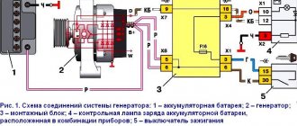
A diode bridge is a circuit that is assembled from connected diodes and converts alternating voltage to direct voltage. It is used in almost all mechanisms that are powered from the network, which is logical: the voltage in the network is alternating, and the electronics operate on constant voltage. Therefore, another name for such a circuit is an AC rectifier.
Despite its simplicity, such a device is much better than a conventional diode. In theory, the use of one semiconductor gives the desired result - voltage conversion. In practice, the output pulsates strongly, so it is not suitable as power supply for electrical circuits. But switching on several diodes in a specific way gives an almost ideal result: the excess half-wave is not cut off, but turned over, due to which the rectification efficiency is greatly increased.
Checking with an indicator screwdriver
This is the simplest test option, which will give a general idea of the condition of the diode bridge and the entire circuit as a whole. To operate, you only need an indicator; the entire procedure is performed under voltage, so extreme caution should be used:
- Touch the tip of the screwdriver to each AC voltage terminal of the diode bridge in turn. If the light does not light, this indicates a fault in the circuit up to the diode bridge - a broken winding, a broken charger, etc. If the light is on, then voltage is supplied to the bridge normally.
Rice. 2. Testing with an indicator screwdriver
- Also touch the positive terminal with a screwdriver - if the light comes on, then the diode bridge normally passes positive half-cycles, respectively, there is potential at this pin. If it does not light, there is damage to the diode bridge.
- Repeat the same procedure with the negative terminal. Be sure to divide the test into both terminals of the rectifier unit, since a fault may be present in any diode and in any branch.
As you can see, in this example an insulated blade screwdriver was used. This is due to the need to perform work under voltage, when you can cover different parts of the electrical installation with a metal part, which will entail extremely unpleasant consequences. A significant disadvantage of the method is its low information content and the limitation on the operating voltage - since the indicator is designed for a nominal value of 220 V, it cannot be used for low-voltage circuits.
Video: Diode bridge. Examination
What does a diode bridge look like?
Finding the rectifier on the board is not difficult, but the appearance varies depending on the device. Often four diodes are soldered side by side and assembled in one housing - this is a rectifier assembly. The photo shows several options:
In such options there are four pins: two are designated as “+” and “-” (outputs), and two without symbols or are indicated as “~” or “AC” (inputs).
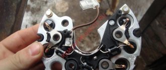
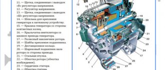
The diode bridge of a car generator looks different: it is a pair of metal conductive plates on which diodes are located in a certain sequence.
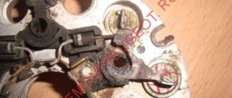
The bridge can have not only power diodes, but also auxiliary diodes:
Here the power diodes are marked in green. It’s better to test everything, especially since it’s not difficult to do.
How to test a generator diode bridge with a multimeter
Instructions for checking the serviceability of the rectifier:
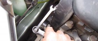
- Disassemble the generator and remove the diode bridge.
- Wash it in gasoline to get rid of oil and dirt (they, by the way, can also cause a malfunction).
- Let it dry and start checking.
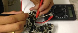
- Install the tester probes into the appropriate sockets. A useful article on how to use a multimeter.
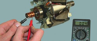
- Select the diode testing mode on the multimeter (in this case it is combined with the continuity function):
- Connect the leads of the meter to each diode terminal. Connect the minus to an aluminum or steel plate, and the plus to a metal core, which is made in the form of tinned bare wire (diameter no less than 1 mm).
- Use one wire to touch the core or plate, and the other to the opposite terminal. After this, swap the probes.
The values of a working diode in one direction will be in the range of 400-700, in the other - infinity or 1. Diodes with plus and minus are checked in the same way.
So you need to test all the diodes. If an element shows 1 in both directions, it means it is damaged.
The values on all diodes should not be very different. If the diode has a serious deviation, it does not work well.
Details of checking the diode bridge of the generator with a multimeter in the video:
Now you know how to test a generator diode bridge with a multimeter.
Checking the generator on the car
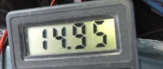
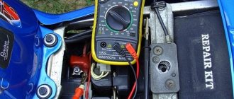
First of all, you need to see if the alternator belt is intact. If it is not torn, then the belt tension is checked. Then it's time for the battery. Using a tester (multimeter), we measure the voltage at the terminals. It should be around 12−12.7 volts. If everything is fine, start the engine. If the battery is discharged, charge it and start the engine again.
We measure the voltage at the battery terminals. It should be within specified limits, usually from 13.2 to 14.5 volts. But on modern cars these limits may differ. If you have an instruction manual, you can read it. Deviation from the specified values in any direction is a malfunction. These deviations can be of three types:
- Lack of charging current - the generator does not work.
- There is a charging current, but below the minimum value -
- Voltage above the maximum value means the battery is overcharged.
All three cases indicate an existing malfunction in the vehicle's electrical supply system. it is necessary to carry out a comprehensive check of the generator.
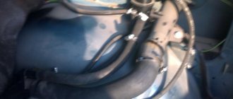
But before that, conduct a visual inspection of all the wires and cables that go from the generator to the battery. There should be no visible damage, breaks or oxidation of the electrical wiring. Be sure to check the terminals on the battery, starter and alternator. They must be clean and dry. Any oxidation, rust or dirt must be cleaned off. Often this helps restore lost contact and the car begins to work as expected. If this does not help, we proceed to a detailed check.
Using a Multimeter
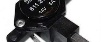
For further inspection, it is better to remove the generator from the car. First of all, remove the relay regulator from the generator and check it. To check the voltage stabilizer, you will need a multimeter and a charger with regulated voltage. It would be better to use a power supply instead of a charger. Voltage adjustment from 0 to 16 volts will be sufficient.
Connect the plus of the power supply to the regulator - usually this is a male plug connection. Hook the minus to the minus, it is usually output to the ear of the relay mount. Connect the red wire of the tester to the positive wire of the power supply, the black wire to the negative wire. Connect two stripped wires to the brushes, one for each. A light bulb is connected to the other pre-stripped ends (it can be removed from the rear lights of the car during testing). The test bench is ready.
Continuity of the relay regulator
Connect the power supply to the network, carefully use the regulator knob to begin raising the voltage. At the same time, monitor the multimeter readings. The light bulb should not light up at the very beginning, but as the voltage rises it should light up, first at half-incandescence and as the voltage increases, the brightness should increase.
When the 14.5 volt mark is reached, the regulator should operate, cutting off the voltage. The light should then go out. It is generally accepted that the stabilizer is working if it cuts off the current at values from 14.2 to 14.8 volts. If this happens at lower or higher values, then the voltage regulator is faulty. The relay is also faulty if there is no current cutoff at all.
If the relay malfunctions, replace it with a new one. If it is working properly, we continue checking.
Checking a bridge with a different structure
How to check the diode bridge of other devices?
The principle of operation is usual (check without desoldering):
- Set the digital multimeter to diode test mode. If you have a pointer unit, select the resistance measurement function with a range of 1 kOhm.
- Ring each diode, connecting the tester probes in one polarity, then in the other. In one direction there will be a small resistance (within 200-700 Ohms), in the other direction continuity is impossible, that is, the multimeter gives “infinity”.
The essence of the check is shown in the picture:
If the results do not correspond to the norm, you need to desolder the bridge. The verification principle is the same as described above. If the diode has high values in both directions, it is open. If it rings in both cases, then the element is broken.
Is it possible to mix antifreeze by color, brand and manufacturer?
- the bridge is dismantled from the generator (no other way);
- each diode will need to be checked separately;
- the beeper mode is selected on the measuring device;
- This setting will allow you to hear a signal when the probe is shorted;
- if this mode is not available, select the 1kOhm position;
- the probes are brought to the edges of the diode;
- a measurement is made;
- the probes are swapped.
Now regarding the measurement results. Everything is fine with the diode, if in one position you see an infinity sign on the screen, in the second it gives a value in the range from 500 to 700 Ohms.
If the device shows a lower resistance value, or there is an infinity sign in two positions, you have found a faulty diode.
Bulb
Now let's see how the procedure is carried out using a regular light bulb. This is a good alternative for those cases when you don’t have a multimeter.
The most ordinary 12 V lamp will do the job.
Safety regulations
Depending on where and which diode bridge you are testing, consider the following:
- Many modern units operate with high-voltage power supplies, that is, the bridges in them are under high voltage! Therefore, before testing, disconnect the device from the network and discharge the smoothing capacitors, which are in the photo under the scarlet arrows. This is easy to do: you can short-circuit the capacitor terminals for a second with a screwdriver, while holding it by the insulating area. If you do not take this point into account, you can lose your life!
- When the repair is completed, you should not directly connect the device to the network. First, turn it on through a lamp (150-200 W). If everything is ok, it will burn a little. But a bright light indicates a short circuit.
- Take care of your eyes and more. Parts of impulse units can explode if repaired incorrectly, and this is very dangerous!
Now you know how to test a diode bridge with a multimeter. Take on the job if you have thoroughly studied safety precautions and are confident in your abilities.
Share your experience in the comments.
We wish you safe and accurate measurements!
How to check without dismantling
You can diagnose the device on site without disassembling the generator or desoldering the part. To do this, unscrew all the wires on the generator and voltage regulator, set the tester to ohmmeter mode, and connect the lamp to the battery in the manner described above.
This method allows you to check the serviceability of the entire bridge and individual groups.
Short circuit
For this test, the positive electrode is applied to output 30 of the generator (“plus” of the power rectifier), and the negative electrode is applied to the housing. A resistance value of 1 indicates that the bridge is in good condition.
One end of the lamp is connected to the negative terminal of the generator, the other to the positive terminal. A lit lamp indicates a short circuit.
Negative group
The negative electrode of the tester is connected to the frame of the generator, the positive electrode is connected to one of the diode bridge mounting bolts. The negative group is operational if the resistance is infinity.
To check with a lamp, connect its minus to the generator casing, and the plus to the axle mounting bolt. The lamp lights up or flashes when there is a malfunction in the negative group of elements.
Positive
The positive probe of the multimeter is connected to the positive terminal, the negative one to the bridge mounting bolt. With a working group, the resistance is infinite.
The negative of the lamp is connected to the bridge mounting bolt, the plus is applied to the positive terminal. A lit lamp indicates a short circuit in the positive semiconductors.
Minor group
The positive electrode of the tester is pressed to terminal 61 (usually the “plus” of the additional rectifier), the negative electrode is connected to any bridge mounting bolt. The diodes are serviceable with a resistance value of 1.
The negative end of the lamp is connected to the bridge mounting bolt, and the positive end is connected to terminal 61. A lit lamp indicates a malfunction in this group.
Bridges can be made of individual diodes or made as a monolithic structure (diode assembly)