You don’t know anything about adjusting the ignition!
Greetings to VAZ car enthusiasts on the RtiIvaz.ru blog! You don’t know anything about ignition adjustment, which is why you need to read the auto article further.
Stable engine operation, its efficiency, throttle response, and power depend on the correct installation of the ignition. The ignition adjustment itself is necessary in order to ignite the fuel-air mixture in a strictly defined sequence, depending on the order of operation of the cylinders.
For self-service, owners of these models need to remember that on VAZ 2105, 2106-07 cars the cylinder operating order is 1-3-4-2.
The operation of adjusting the ignition on VAZ 2105 and VAZ 2106-07 cars may be required in several cases. This must be done after a medium or major overhaul of the engine, replacing the block gasket, valve burnout, replacing the timing chain or belt, replacing the camshaft and other similar cases associated with partial disassembly of the engine.
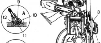
To set the top dead center and adjust the ignition, there are special marks on the engine in its upper and lower front parts that must be aligned. Location of marks on VAZ 2106 and VAZ 2105 engines for adjusting the ignition system.
Cold start rules
Compliance with them will help to avoid the negative impact of sub-zero temperatures on the life of the car:
- First, you need to warm up the electrolyte in the battery; to do this, turn on the side lights for 5-10 seconds.
- Next, you should check whether all electrical consumers are turned off (fan, oven, heated seats, etc.) - this is necessary to relieve the battery of unnecessary loads.
- The next step is to turn the starter on for no more than 5 seconds. Operating the starter for more than 5 seconds is dangerous for maintaining battery charge. All subsequent attempts to turn it on should also be made with a break of 10 seconds so that the battery has time to partially restore its charge.
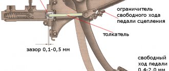
- When, after these manipulations, the engine starts working, under no circumstances should you immediately release the clutch pedal and do it abruptly, because the mechanism needs to gain stable speed. The engine will not stall if the pedal is lowered smoothly and slowly.
- The last rule, failure to comply with which can lead to car damage - if the engine does not start, then there is no need to repeat the entire algorithm until the battery is completely discharged. Three or four unsuccessful attempts are enough, after which you should understand that the culprit for not starting the car is not frost, but some other malfunction.
VAZ 2106 – timing chain
Upper marks: one mark in the form of a hole is applied to the camshaft sprocket from the inside, the second mark is a boss in the form of a protrusion at the end of the camshaft bed. To perform this operation, the valve cover must be removed.
The lower marks on the front engine cover are cast into 3 marks - one long and two short, and on the crankshaft pulley there is a molded boss on the inside (you can easily feel it with your hand) and a mark on the end of the pulley. The long mark corresponds to the top dead center, and the two short marks are the ignition timing marks.
The first short mark (the middle of the three) corresponds to an ignition advance of 7.5 degrees, this is actually the factory tolerance for installing the ignition when using AI 92-95 gasoline. The second short mark corresponds to an ignition advance of 10 degrees.
When assembling the engine during a major overhaul, the crankshaft is oriented along the internal marks. This is a mark on the sprocket (risk) of the crankshaft and a boss on the cylinder block, which are combined.
Then the timing chain is installed and the marks on the camshaft sprocket and its bed are aligned. The crankshaft is turned two turns and the alignment of the marks is checked again. If all marks match, then install the front engine cover, crankshaft pulley and valve cover.
When installing the distributor (ignition distributor), the above-mentioned valve timing marks are set, and the distributor slider, after installing it, should point with the spacer plate at the 4 cylinder wire socket in the distributor cover.
VAZ 2105 – timing belt
Upper marks: one mark “E” is located on the cover of the first journal of the camshaft, and the second “F” is applied to the camshaft pulley. In order to “get” to the marks, you need to remove the timing belt protective cover. The lower marks are similar to the VAZ 2106-07 (the designation of the marks “C” on the pulley and “D” on the cover, while three long and two short marks are marked on the protective cover of the timing belt).
Video of adjusting the ignition of VAZs for any purpose
To check and adjust the ignition using an ohmmeter, do the following:
A similar adjustment of the ignition angle can be performed using a control lamp, but care must be taken since this operation is performed with the ignition on.
One wire from the lamp is connected to ground, and the second wire is connected to the distributor bolt, as is the case with an ohmmeter.
Further everything is the same as using an ohmmeter. The correct installation of the ignition is checked during a test drive. To do this, the engine is started, warmed up to operating temperature and a test drive is made to check and adjust the ignition. The following steps are performed:
The car accelerates to 50 km/h and the gas pedal sharply sinks into the floor. If everything is set correctly, you should hear 3-4 finger clicks. If the clicking of the fingers is longer, then this indicates that the ignition is set early; if there are no clicks at all, then the ignition is late.
With early ignition, the distributor must be turned clockwise, and with late ignition, counterclockwise and repeat the tests again.
Next, look at the video to see what electronic ignition looks like on a VAZ 2101, 2106, 2107 and contact:
All these installation and inspection work, ignition adjustments are carried out provided that the timing chain or belt is tensioned with the correct tension. And you also need to make sure that the engine valve clearances are adjusted, right.
Source
Instructions for setting the ignition
If you strictly followed the instructions, connected all the wires according to the diagram and did not misalign the marks, then the motor will start without problems. To adjust the ignition, you need to ensure stable engine operation, so first warm it up for a few minutes, without letting it stall by pressing the gas pedal.
Advice . If the engine does not start successfully, and when you turn on the starter there is not even a popping sound, then you probably made a mistake with the wiring. Check everything again according to the diagram included with the factory set of electronic ignition parts.
Adjustments can be made on a warm engine using two methods:
- without the use of special devices - “by ear”;
- fine adjustment using a strobe light.
A strobe is a device with a light bulb that flashes simultaneously with the transmission of a pulse by the Hall sensor. When the switched on strobe is brought to the crankshaft flywheel with the engine running, the position of the notch becomes visible. Hence the possibility of precise adjustment.
This is what a strobe looks like for fine-tuning the ignition
To set up, connect the strobe power supply to the battery, and the thick wire to the high-voltage wire of the spark plug of the 1st cylinder. Loosen the distributor fastening nut and bring the flashing lamp to the pulley. Slowly turn the distributor body until the notch on the pulley aligns with the short notch, then tighten the nut.
Tuning in the traditional way “by ear” is done like this:
- Start the engine and loosen the nut holding the ignition distributor.
- Rotate the distributor smoothly and slowly within 15°. Find the position at which the motor operates most stably.
- Tighten the fastening nut.
When adjusting, turn the distributor by the membrane body
Advice . When you turn the ignition distributor by hand, try not to touch the high voltage wires so that you do not get an electric shock. The best option is to grab the body of the membrane mechanism, where the tube from the carburetor is attached.
It is quite natural that after installing a contactless ignition system, the engine idle speed will increase to 1100-1200 rpm due to the increased spark power. Set the rate to 850-900 rpm by tightening the idle screw on the carburetor and using the tachometer as a guide. On VAZ 2105-2107 carburetors of the “Ozone” type, this screw is located in the lower section of the unit on the right side and is large in size. The VAZ 2108 carburetors of the Solex type (these were also installed on the “seven”) have a long plastic handle protruding from the right (in the direction of travel). The second screw, which regulates the composition of the air-fuel mixture, cannot be turned.
The arrow shows the idle speed adjustment screw.
Advice . If, when you sharply press the accelerator, a loud knock is heard from the engine, then you have set the ignition timing too high and the mixture flares up earlier than necessary. Loosen the distributor nut and turn the housing a couple of degrees clockwise.
The best indicator of successful installation and configuration of a contactless ignition system is checking the VAZ 2107 while driving. It’s worth driving the car for several kilometers to check it in different modes - acceleration, driving in a straight line and coasting with the gear engaged. You will probably like the behavior of the car, and the annoying cleaning of contacts will be forgotten forever.
Replacing timing belt lada 2103 (vase 2103)
The timing belt connects the engine camshaft and crankshaft and synchronizes them with each other.
During operation, it is not the links themselves that change the dimensions, but the joints are erased, the hinges are worn down, and as a result, play in each link appears. They all add up, so the change in size is quite significant. Signs of the need to replace the timing chain are determined, in most cases, by eye. The possibility of tension is checked; if it is absent, there is no wear, operation is normal. A more precise check can be carried out - in phases. The mark of the bearing housing on the camshaft must coincide with the mark of the sprocket. If the mark on the crankshaft pulley is lower than the mark on the engine cover by more than 10 mm, the chain must be changed. Replacement is also necessary if cracks appear on chain links or bushings are chipped.
Contact ignition system (carburetor)
Old "sevens" with a carburetor engine, as a rule, are equipped with a classic contact system. To accurately check and adjust the ignition, a strobe is needed, but due to the rarity of such a device, a simple 12-volt light bulb can be used. Prepare two keys - for the crankshaft and an open-end one for “thirteen”.
Installation of the ignition of a VAZ-2107 equipped with a contact system is carried out as follows:
- Turn off the engine (if it was running) and wait until its temperature drops to a safe level. Place the piston of the 1st cylinder in the desired position. To do this, unscrew the spark plug from the 1st cylinder, close the hole and turn the crankshaft in the direction of rotation of the clock hand.
- Wait for maximum pressure on your finger. Rotate the shaft until the mark on the pulley aligns with the notch on the timing case. If you have problems finding the marks, wipe the surface from dust and dirt.
- If it matches the second mark, we can talk about the ignition advance by 5 degrees. If you fill with fuel with an octane rating of 92 or 95, you can leave this parameter. Remove the key from the crankshaft, screw the spark plug into place and return the contacts to their place.
The next task is to determine the ignition timing. To do this, work with a distributor. Take the key to “thirteen” and make several rotations of the nut in the direction of unscrewing. The following is the algorithm:
- Take a 12 Volt lamp and connect two power wires to it.
- Connect one of them to the machine ground, and the second to one of the coil terminals (the one from which the secondary voltage comes out).
- Scroll the distributor cap. Rotate until the lamp goes out.
- Put everything back in the same position and use the car.
As a rule, such a setting of the ignition timing of the VAZ-2107 gives good results and helps solve a number of problems - eliminate starting problems, reduce fuel consumption and even improve the dynamics of the car.
Adjustment or how to set timing marks on a VAZ 2106 yourself
Decoding notes
Without pre-basing the pistons and valves, installing the timing chain on the VAZ 2106 according to the marks is impossible. Therefore, the significance of the marks is not at all conditionally decorative. The signs give an understanding of the position of parts inside the motor:
For your information. The numbering of the “pots” starts from the radiator side.
How to restore tag matches
When the chain is pulled out, the marks will go away. The main difficulty is to return them to a position of mutual coincidence. This work is combined with dismantling the old chain. However, there is no need to rush to remove it - misalignment of all factory markers is fraught with danger.
The base is the position of the crankshaft at which the pulley mark coincides with the long line on the front cover. In this case, the drilling hole for the camshaft star should be closer to the high tide. This must be achieved first. It is worth remembering that the transmission is made with a 2:1 ratio - two revolutions of the crankshaft correspond to one revolution of the camshaft.
Unnecessary fears when dismantling the RV sprocket are not appropriate. The shaft design includes a pin. In addition to transmitting torque, it serves as a fixator of a certain position.
How to put on a chain
Installation of a new chain begins with its attachment to a new crankshaft sprocket. Next, the damper, tensioner shoe, and limiter are mounted. The chain is passed through the drive shaft gear and secured along the way. Afterwards it is mounted on the camshaft sprocket, and its position is adjusted according to the cycle:
The final procedure is to tighten the chain, during which the tensioner is twisted all the way with good force. After rotating the HF key, the final check of the coincidence of the signs is carried out.
Methods for diagnosing device performance
The simplest method that will help determine the performance of the coil is to replace it with a similar working device. This is possible if there is somewhere to get it. Please note that the module must match the parameters of the device under test. If the engine with a working coil works as before the breakdown, the ignition module is definitely faulty.
The main testing method involves using a multimeter. It consists in determining the resistance of the secondary windings of the coils built into the ignition module. The method is simple and does not require additional skills. The device does not need to be removed for testing. The check is done with the engine turned off.
This is how you check the resistance of the secondary winding with a multimeter
- High-voltage wires are removed from the module sockets.
- The tester switch is set to the 20 kOhm position.
- The multimeter rods are placed in turn in the recesses of the corresponding contact pairs (1 and 4, 2 and 3).
- With an intact secondary winding, the performance in both cases is the same. Normally, the resistance should be about 5.4 kOhm (in some models the indicators differ, which needs to be clarified). If the resistance is much greater, then there is a winding break. The resistance is much lower - a breakdown. The coil is faulty and cannot be repaired.
Video: How to check the secondary winding with a multimeter
Lada 2106 Ivory 1.3 › Logbook › Replacing the chain
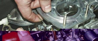
Work order: 1. Remove the housing part of the filter for cleaning incoming air masses from the upper plane of the carburetor, for which we unscrew 3 nuts from the housing cover and 4 fasteners at the base of the housing. When dismantling the product, you must not drop the fasteners or keys into the carburetor chamber, otherwise problems will arise, including removing the intake manifold. 2. Unfasten the cover of the breaker-distributor from the latches and disconnect the fuel pipeline. 3. Unscrew the fasteners of the over-valve casing and carefully remove the washers with plate elements from the mounting sockets. 4. Dismantle the cable with the throttle valve drive. 5. We lift the over-valve casing, freed from its fastenings, together with the gasket made of oil-resistant rubber, which needs to be replaced due to loss of tightness, and remove it. 6. We dismantle the engine crankcase protection and, after unscrewing the drain plug from the radiator, drain the antifreeze into a previously placed reservoir. 7. Slightly unscrew the tensioning upper fastener of the generator machine. 8. Loosen the fastening of the bottom pipe of the water pump and dismantle it. 9.De-energize the fan and temperature sensor on the radiator housing. 10. We dismantle the elements of the cooling system (radiator, pipes and thermostat). 11. Dismantle the generator belt drive. 12.Using a special crankshaft wrench, rotate the shaft until the marks on the casing and pulley, as well as on the sprocket gear and the housing (bed) of the timing camshaft, align. 13. Unscrew the crankshaft pulley fasteners with a “36” wrench. 14. We stop the rotational movement of the pulley with a special key or improvised means, after which we unscrew and dismantle this part. 14. We release the camshaft drive cover from the fasteners and dismantle it. 15. We unscrew the tension system fasteners and, if necessary, replace the VAZ 2106 chain tensioner with preliminary removal. Due to the more common installation of an automatic tensioner in the timing system, we are considering this option. We unscrew the fasteners of the camshaft sprocket gear and dismantle it. We recommend marking the position to be centered with a marker or storing this information in memory. 16. We dismantle the tensioner safety device, the tensioner itself, the fasteners for the star gear of the drive of additional mechanisms and the sprocket. 17. We check that the marks match, and the mark on the crankshaft should be aligned with the boss on the cylinder block. After the work has been done, you can proceed to the following steps. Installing and replacing the VAZ 2106 timing chain is carried out in the following mode:
Installation of electronic ignition
Electronic ignition makes engine operation smoother and softer, makes it easier to start in the winter, and reduces fuel consumption. If you, having a carburetor engine, decide to switch to contactless (electronic) ignition, we will tell you how to correctly install it on a VAZ 2107 car.
An electronic system for a car with a carburetor should not be too expensive or cheap. It is best to opt for a product in the mid-price category, so that later you don’t have to change anything after a while.
Before work, prepare a drill and a set of keys.
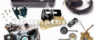
For an overview, first read the included instructions carefully and open the carburetor type engine kit. It includes:
- ignition coil;
- distributor;
- switch;
- 4 candles;
- connecting and high-voltage wires.
The system is easy to install. First of all, remove the negative terminal from the battery and turn the crankshaft until marks numbered 3 and 4 align, that is, the highest dead center.
Now you can begin the main steps. The coil should be disconnected from all wires, remove it and install a new one. The coil can now be connected to the central high voltage wire. Connect 2 brown wires to contact “K”, and 2 blue wires to contact “B”.
Now remove the distributor cover. Please note that the slider must be set exactly as shown in the picture. Mark this place with a marker on the block to correctly install the new distributor. Now you can unscrew this part and put it to the side.
After opening the cover of the new distributor, place the slider perpendicular to the engine and insert it into the hole in the cylinder block. Align it with the mark on the block. Next, put on the cover and connect the wires.
Decide where the switch will be located, since there is no space for it in the VAZ 2107 car. We recommend installing it next to the washer reservoir. Secure it with self-tapping screws and install the connector.
Don't forget the candles. To replace them on a VAZ 2107 car, you will need a spark plug wrench, which you should use to unscrew the old spark plugs from the cylinders and put new ones in place.
Their color can say a lot about the engine's performance, so if the spark plugs have black carbon deposits, the air filter should be replaced. Normally, candles should have a light brown color.
Nuances in installing a timing chain according to factory marks on a VAZ 2106: pitfalls
It is difficult to achieve perfect alignment of two pairs of marks. The main reason is the use of components with dimensions within the maximum limit. By the way, adjusting the VAZ 2106 carburetor with your own hands also never follows the ideal scenario - additional recommendations from experienced craftsmen are almost always used.
Allowable elevation shifts
One of the unwritten norms allows for a discrepancy between the sprocket drilling and the camshaft bearing housing boss within a half-tooth in one direction or another. To be more specific, the installation of the timing chain of the VAZ 2106 engine according to the marks is considered complete when the camshaft sprocket is aligned exactly, and the mark of the crankshaft pulley goes slightly forward. This guarantees stable traction throughout the entire speed range.
If the camshaft star is aligned with the mark, and the knee pulley does not reach the TDC mark, the engine operates stably only up to a speed of 100 km/h. After crossing the border, there is a loss of traction and increased fuel consumption.
Extremes
A discrepancy of one tooth between the timing marks and the camshaft sprocket is unacceptable. This is usually evidence of critical chain stretch. When it is new, it is worth inspecting the seat under the key on the crankshaft - perhaps it is broken, hence the excessive play.
Engines with significant mileage are often prone to arbitrary changes in the location of the RV star mark during the rotation of the HF. This leads to:
For your information. Using a split star helps achieve perfect mark placement. It is installed to replace the standard camshaft gear.
How to determine early or late ignition
When the OZ shifts in one direction or another, this causes a noticeable drop in engine power. But this phenomenon can also manifest itself with other symptoms:
- problems when trying to start the engine;
- a noticeable increase in fuel consumption;
- unstable work at XX;
- deterioration in dynamics when pressing the accelerator pedal;
- the occurrence of detonation processes;
- characteristic pops emitted into the exhaust system;
- engine overheating.
If you do not respond to these signs of unstable operation of the power unit, they can result in more serious problems. You need to be especially careful when persistent detonation occurs.
Let's look at specific signs of early ignition:
- increased engine detonation, threatening destruction of connecting rods and the occurrence of piston defects;
- loss of power, which is clearly noticeable at low speeds;
- the appearance of knocking in the engine;
- increase in fuel consumption.
Let's look at the symptoms of late ignition, which overlap:
- drop in power, especially at high speeds;
- problematic start of the power unit;
- motor overheating;
- decreased fuel efficiency.
As you can see, problems arise with any change in the ignition angle. And yet, many motorists take such a step at their own peril and risk. Some - by installing the ignition earlier, so as not to experience problems with starting. Others prefer late ignition, which improves the car's dynamics during acceleration. Both cases are undesirable because they negatively affect the engine.
It should be noted that the installation of LPG places increased demands on car owners in terms of optimizing the ignition angle. Currently, switching to compressed gas makes it possible to reduce fuel costs by almost half, but it must be taken into account that this fuel has a higher octane number compared to gasoline, and it is consumed somewhat faster than gasoline. All this leads to the fact that the combustion of the combustible mixture can occur during the exhaust stroke, exerting a strong thermal effect on the exhaust system. That is why owners of cars with gas equipment should monitor the functioning of the power unit much more often.
The symptoms of an incorrectly set ignition angle are also typical for diesel engines, but the reasons for this phenomenon are fundamentally different. The fact is that the method of igniting fuel in a diesel engine is different: here air is supplied directly to the combustion chamber, that is, there is no stage of preparing the fuel assembly. Diesel fuel is fed into the cylinder, where it spontaneously ignites when in contact with highly compressed air heated to a temperature sufficient to ignite the diesel fuel.
Adjusting the late/early ignition timing involves accurately setting the diesel fuel injection timing exactly at the moment the piston passes TDC, and the main element of the ignition system for diesel power units is the high-pressure fuel pump, which is responsible for optimal fuel injection.
Timing marks on a VAZ 2107 car injector
Both on the carburetor engine of the VAZ 2107 car and on the injection engine, the gas distribution mechanism along with the drive remained the same, that is, chain. With excessive wear and stretching of the chain, a number of the following negative consequences are observed:
To avoid such negative consequences, it is necessary to carry out preventive work in a timely manner. We will learn more about how to set timing marks on a VAZ 2107 Lada family car with an injector power system.
Operating principle of BSZ
Electronically controlled spark generation operates according to a fairly simple algorithm, which determines the reliability of such a circuit. When the driver turns the key in the ignition switch, a constant voltage from the on-board network is applied to the primary winding of the coil, causing a magnetic field to form around it.
Then the system works like this:
- The starter turns the crankshaft and drives the distributor shaft along with the slider.
- The Hall sensor, which reacts to the passage of a metal mass nearby, registers the rotation of the shaft along the protrusion on it and sends a signal to the switch.
- The electronic unit, based on a signal from the sensor, turns off the voltage supply to the primary winding of the coil.
- At the moment the circuit breaks, a high voltage pulse (up to 24 kV) is formed in the secondary winding of the coil. It is directed along a thick wire to the moving contact of the distributor.
- The slider redirects the impulse to one of the fixed contacts built into the cover. From there, the voltage goes to the spark plug of the cylinder where the piston is at top dead center.
- At this moment, the fuel is already in a compressed state in the combustion chamber. When a spark jumps across the electrodes of the spark plug, it ignites.
- The runner rotates and transmits a spark to all cylinders according to the 1-3-4-2 scheme, after which the car engine starts and starts working.
Note. In old VAZ 2107 cars there was no switch, and the electrical circuit was broken mechanically - the shaft cam opened the contact group.
Outdated circuit with contact breaker
Timing phases and when to set them according to marks
Valve timing refers to those moments at which the piston in the engine moves up and down over a certain interval. When irregularities in the valve timing occur, the pistons move incorrectly along the interval, resulting in uneven engine operation on the VAZ-2107.
If the driver notices that the car’s power decreases, fuel consumption increases, and engine interruptions occur, then it is necessary to resort to setting the valve timing according to marks. How to set marks on a VAZ 2107 carburetor and injector, we will learn from this material, since the design of the timing mechanism is identical.
How to set timing timing marks
The procedure involves performing the following manipulations:
This relative arrangement of the parts allows the piston of the 4th cylinder to be positioned at top dead center TDC.
Features of servicing the timing mechanism
After the timing marks are installed on the VAZ-2107, you need to perform the following actions:
The process of adjusting the valves on the VAZ-2107 is carried out according to the following scheme: initially 6 and 8 valves are adjusted, the report must be carried out from the radiator. After they are adjusted, you need to start adjusting valves 4 and 7, then valves 1 and 3, and finally valves 2 and 5.
Why is it necessary to set the ignition?
Correctly adjusted ignition timing allows the VAZ owner to both save fuel and improve the dynamic characteristics of the car and get rid of problems with starting the engine in the cold season.
The machine is supplied for sale with properly adjusted components and assemblies, but over time the adjustment gets lost. This fate does not bypass the ignition system either. In the latter case, the power plant ceases to operate in optimal mode, and too strong detonation often occurs in it, which, in turn, leads to accelerated wear of the main elements.
Accordingly, VAZ owners periodically have to independently set the ignition. Less experienced drivers are forced to turn to workshops for this, whose services are very expensive. Expenses can be avoided if you master all the subtleties of adjustment.
Currently, there are two main ways to configure the system in question. Let's say right away: each of them is correct. Some experienced drivers use the so-called experienced method, others prefer to make adjustments using a strobe light. Both options have both advantages and disadvantages, the sum of which does not allow us to clearly determine the most preferable one.
How the timing chain drive of the VAZ 2106 car works: review and replacement
The popular VAZ 2106 car, whose production began during the Soviet era, was equipped with three types of engines - with a displacement of 1300, 1500 and 1600 cm3. The design of the listed motors is the same, the difference is only in the sizes of the cylinder-piston group, crankshaft and connecting rods. On all power units, the timing gears are driven by a double-row chain. The latter gradually stretches out and needs periodic tightening; the minimum service life of the part is 100 thousand kilometers. When tensioning does not produce results, the entire chain drive is changed - along with the gears.
What are the dangers of an incorrectly set OZ?
So, we have already found out that if the ignition of the fuel assembly in the form of a spark generated by the spark plug occurs earlier than usual, the expansion of the compressed mixture as a result of its combustion will begin to occur even before the piston has passed TDC, that is, at the stage of its ascent. This means that it will be more difficult for the piston to travel the rest of the way up before it begins to move downwards, during which the optimal release of energy from the exhaust gases occurs.
With late ignition, the amount of useful work performed by the piston also decreases, since part of the path it will travel by inertia, and part of the energy will be wasted and sent to the exhaust system, warming it up instead of increasing the efficiency of the power unit.
The consequences of an incorrectly set ignition can be very serious. If you allow the engine to operate for a long time at a late ignition, all the conditions for the optimal combustion process will be violated. In particular, at the moment at which the exhaust gas pressure peaks, the piston is already moving downwards, so the entire fuel assembly does not have time to burn, which leads to the deposition of unburned particles on the cylinder walls. Accumulating, such deposits can lead to coking of the engine, which can lead to its breakdown and the need for major repairs.
Purpose and design of the drive
The gas distribution mechanism is responsible for supplying the fuel mixture to the cylinders and releasing exhaust gases. To ensure timely opening of the intake and exhaust valves, the camshaft must rotate synchronously with the crankshaft. In the Zhiguli, this function is assigned to a chain drive installed in the front of the engine.
Replacing the timing chain and gears cannot be classified as complex operations, but the procedure is quite labor-intensive. To do the work yourself, you need to understand the operating principle and design of the drive, which consists of the following elements:
The gear size ratio is approximately 1:2. That is, while the crankshaft drive sprocket makes 2 revolutions, the camshaft gear rotates 1 time.
The required tension of the VAZ 2106 timing drive is provided by a plunger device supporting a semicircular shoe. Older cars were equipped with a purely mechanical plunger - a retractable rod with a powerful spring, which had to be tightened manually. Later models received a hydraulic chain tensioner that operates automatically.
Unknowingly, I once found myself in a stupid situation. A friend’s chain on the “six” was stretched out and began to make a lot of noise, I advised it to be tightened. On site it turned out that the plunger fixing bolt was missing; the advice turned out to be useless. Later it turned out that the car has an automatic tensioner that is activated by oil pressure. The stretched chain had to be replaced.
The timing drive is lubricated by engine oil coming from the camshaft. To prevent lubricant from splashing, the mechanism is hidden behind a sealed aluminum cover, screwed to the end of the cylinder block with 9 M6 bolts. Another 3 screws connect the protective casing to the oil pan.
So, the chain drive performs 3 functions:
What is ignition timing?
For the ignition to work correctly, the following condition must be met: sparking must occur at the moment when the piston is at TDC. This should be a compression stroke. This moment should be the flash point.
| Options | Units | Classical | Contactless |
| Spark energy | mJ | 20 | 60 |
| Secondary voltage rise time from 2 to 15 kV | mks | 30 | 20 |
| Secondary voltage max | kV | 26 | 29,5 |
| Spark duration | ms | 1,5 | 2 |
However, that's not all. The time it takes for the fuel mixture to completely burn must also be taken into account. Therefore, the spark plugs must create an impulse with some advance, which is called the advance angle. As a result, the mixture reaches the peak of combustion, and the cylinder begins to move downward.
If sparking occurs earlier, then such ignition is called earlier, and if late, then later. Early leads to detonation. This is why the engine quickly overheats and becomes inefficient, although fuel consumption can sometimes be greatly reduced. This can be determined by the spark plug electrodes, which are covered with a white coating. With late ignition, power is noticeably lost, and black smoke comes out of the exhaust pipe, which indicates that gasoline, without having time to burn in the cylinder, burns out in the exhaust system.
The spark plugs, in this case, turn black. Popping noises in the exhaust pipe can also tell this. Late ignition means that the spark plugs are simply flooded with fuel, which does not burn or burns incompletely. When they are flooded, they do not work.
Ignition systems are divided into 3 groups:
Contact ignition system
Contact ignition system
Contactless ignition system
Contactless ignition system
Electronic ignition system (microprocessor ignition system)
Electronic ignition system
Pros and cons of contactless ignition
Pros and cons of contact ignition
Pros and cons of an electronic ignition system
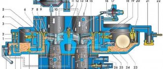
Design of VAZ 2103 and VAZ 2106 engines
Design of VAZ 2103 and VAZ 2106 engines
VAZ 2103, 21061, 2106, 2121, 21053, 2107 cars are equipped with VAZ 2103 and VAZ 2106 engines. They are of the same design, but with different cylinder capacities. They differ mainly in the dimensions of the cylinder block, pistons, and the length of the timing chain (116 links); there is also a difference in the shape of the tensioner shoe, or more precisely in the location of the tensioner thrust bracket on it due to the difference in the weight of blocks 2101, 21011 and 2103, 2106 The last blocks are 9 mm higher than the first ones, so the engines use chains of different lengths and different shoes. On engines 2101,21011 the tensioner shoe is marked 2101, and on engines 2103,2106 it is marked 2103.
At the bottom of the cylinder block there are five supports for the main bearings of the crankshaft with thin-walled steel-aluminum liners (Attention: when installing the liners, it is mandatory that liners with circular grooves on the inside are installed in the block at the point of contact in the crankshaft for continuous lubrication of the connecting rod liners when the shaft rotates, in the covers smooth liners without grooves are installed. The liners of the middle - 3rd journal are wider than the others and both are smooth, the rest are the same width.) The holes for the crankshaft bearings in the cylinder block are machined together with covers, so the bearing covers are not interchangeable, and to differentiate on their outer There are risks on the surface.
In the front part of the cylinder block there is a cavity for driving the gas distribution mechanism, closed by a cover in which the front crankshaft oil seal is installed. On the rear side, a rear cover with a crankshaft oil seal is attached to the cylinder block. On the left side of the block there is a drive shaft for auxiliary units (pig). Steel-aluminum bushings are pressed into the holes for the roller bearings. (Attention: currently bushings are produced from a copper-plated material of the corresponding color; when installing them, it is not allowed to install them too tightly, unlike steel-aluminum ones, since biting is possible when the engine heats up and the pin on the pig is cut off as a result of a violation of the timing belt installation and bending of the block head valves, except for engines on which pistons 2105 are installed in sizes 79.00; 79.4; 79.80; 80.00.
The cylinder head is common to four cylinders and is cast from aluminum alloy. Cast iron seats and valve guides are pressed into the head. Spiral grooves for lubrication are cut into the holes of the guide bushings. To reduce the penetration of oil into the combustion chamber through the gaps between the bushing and the valve stem, metal-rubber oil deflector caps are used. The cylinder head is attached to the cylinder block with eleven bolts. Between the head and the cylinder block there is a gasket made of asbestos material on a metal frame and impregnated with graphite.
The pistons are made of aluminum alloy. The piston skirt is oval in cross section and conical in height. In addition, steel temperature control plates are cast into the piston bosses. All this is done to compensate for the uneven thermal deformation of the piston when heated. The piston bosses have holes for oil to pass to the piston pin. The hole for the piston pin is shifted from the axis of symmetry by 2 mm to the right side of the engine to reduce the knock of the piston when passing through TDC. Therefore, near the hole for the piston pin there is a “P” mark, which during assembly should face the front of the engine. Pistons, like cylinders, are sorted into five classes by outer diameter every 0.01 mm, and by diameter of the piston pin hole - into three categories every 0.001 mm, designated by numbers 1. 2, 3. Piston class (letter) and hole category under the piston pin (number) are stamped on the bottom of the piston. Pistons in terms of weight in the same engine must be selected with the maximum permissible deviation (2.5 g).
Piston panels are made of cast iron. The outer surface of the upper compression ring is chrome-plated to increase wear resistance and has a barrel-shaped generatrix to improve run-in. The lower compression ring is scraper type (with a groove along the outer surface), phosphated. The ring must be installed with the groove down. The oil scraper ring has slots for oil removed from the cylinder and an internal coil spring (expander). The connecting rods are steel, forged, with a split lower head in which the connecting rod bearing shells are installed. The connecting rod is processed together with the cover, so when assembling, the numbers on the connecting rod and the cover must be the same. The crankshaft is five-bearing, cast iron. The shaft journals are hardened by high frequency currents to a depth of 2-3 mm. At the rear end of the crankshaft there is a seat for the front bearing of the gearbox input shaft, along the outer diameter of which the flywheel is centered. The flywheel is installed on the crankshaft so that the mark (a cone-shaped hole near the toothed rim of the flywheel) and the axis of the connecting rod journal of the first cylinder are in the same plane and one at a time from the axis of the crankshaft. The main and connecting rod bearing shells are thin-walled, steel-aluminium. All connecting rod bearings are the same and interchangeable. The upper shells of the 1st, 2nd, 4th and 5th main bearings are the same, with a groove on the inner surface, and the lower shells are without a groove. The shells of the 3rd main bearing differ from the others in their larger width and the absence of a groove on the inner surface. The gas distribution mechanism ensures that the engine cylinders are filled with a combustible mixture and exhaust gases are released in accordance with the cylinder operation order and valve timing adopted for the engine. The mechanism parts include: camshaft, valves and guide bushings, springs with fastening parts, valve drive levers. The camshaft, which controls the opening and closing of the valves, is cast iron. The rubbing surfaces of the cams are bleached. This process consists of electric arc melting of surfaces, which results in the formation of a layer of so-called “white” cast iron, which has high hardness. The shaft rotates on five supports in a special housing, and is kept from axial movements by a thrust flange placed in the groove of the front support journal of the shaft.
The valves (intake and exhaust) are located in the cylinder head obliquely in one row. The intake valve head has a larger diameter for better cylinder filling, and the operating chamfer of the exhaust valve, which operates at high temperatures in the aggressive environment of exhaust gases, has a heat-resistant alloy overlay. The springs press the valve to the seat and do not allow it to come off the actuator lever. The upper support plate of the springs is held on the valve stem by two crackers, which when folded have the shape of a truncated cone. The levers transmit force from the camshaft lobe to the valve. The lever rests on the spherical head of the adjusting bolt with one end, and on the end of the valve with the other. The adjusting bolt is screwed into the bushing and locked with a locknut. Drive of auxiliary units. The engine auxiliary components and timing mechanism are driven from the crankshaft using a chain drive. It consists of a double-row bush-roller chain of the “Gall” type. the drive sprocket on the crankshaft, the camshaft driven sprocket, the chain guide and the tensioner with shoe. The tensioner shoe and chain guide have a steel frame with a vulcanized rubber layer. When the locking nut is unscrewed, the chain is tensioned by the shoe, which is acted upon by springs through a plunger. The tensioner shoe rotates around the mounting bolt. After tightening the nut, the rod is clamped by the antlers of the cracker, as a result of which the chain tensioner spring is blocked.
When the engine is running, only the internal spring acts on the plunger, which, thanks to a gap of 0.2-0.5 mm in the tensioner mechanism, provides compensation for chain vibrations. The chain damper dampens vibrations of the leading branch of the chain. When the engine is running, the chain is stretched. It is considered operational if the tensioner ensures its tension, i.e. if the chain has stretched no more than 4 mm. The drive shaft of the oil pump, ignition distributor and fuel pump is installed along the engine and has two support journals, a helical gear and an eccentric, which drives the fuel pump through a pusher. The shaft helical gear meshes with a gear that drives the ignition distributor and oil pump.
The gear rotates in a cermet bushing pressed into the cylinder block. The gear has a splined hole into which the splined ends of the ignition distributor and oil pump rollers fit. Engine operation. During one working cycle, four strokes of hot mixture intake, compression, power stroke and exhaust gases occur in the engine cylinder. These strokes are carried out in two revolutions of the crankshaft, i.e. each stroke occurs in half a revolution (180) of the crankshaft. The intake valve begins to open 12 minutes before the piston approaches top dead center (TDC). This is necessary to ensure that the valve is fully open when the piston goes down. The valve closes 40 after the piston passes the bottom dead center (BDC).
Due to the inertial pressure of the jet of the sucked-in combustible mixture, it continues to enter the cylinder when the piston has already begun to move upward, thereby ensuring better filling of the cylinder. The exhaust valve begins to open 42 before BDC. At this moment, the pressure in the cylinder is still quite high, and gases begin to flow intensively out of the cylinder. The valve closes 10 minutes after the piston passes TDC. There is a moment (22 turns of the crankshaft near TDC) when both intake and exhaust valves are open simultaneously. This position is called valve overlap.
On your own. Adjusting the ignition
It is known that correctly selected ignition timing ensures the best power and economic performance of the engine, maintains optimal thermal conditions and helps increase the durability of its main parts.
The most advantageous ignition timing is determined on benches during factory tests and the instructions indicate the amount of advance that should be followed during adjustment.
The influence of ignition timing on engine characteristics is presented on the tab in the form of curves of the dependence of pressure in the cylinder on the position of the piston at various advance values - “normal”, “early” and “late” (Fig. 1). It is easy to notice that with optimal advance, the rapidly growing pressure of the resulting gases reaches a maximum immediately after the piston passes the top dead center. As a result, the most efficient operation of the engine is ensured - in our graphs it is characterized by the area limited by the curve. At the first stage, this area (that is, the useful work of one cycle) is maximum, which provides the greatest power and, under given conditions, efficiency.
The second graph shows a case of too much ignition timing, called early. What happens in the cylinder? As we can see, the pressure in it begins to increase rapidly at the moment when the piston is still far from the top dead center, reaches its maximum and... by the time the piston reaches the top point it begins to fall! The top of the curve forms a "loop" (shaded area) which represents harmful, negative cycle work that prevents the crankshaft from rotating. As a result, the load on all the main parts of the engine increases, it works “hard”, with metallic knocks. The maximum pressure in the cylinder often significantly exceeds the normal design value, which almost inevitably results in detonation, that is, abnormal combustion of an explosive nature. This, in turn, further increases the negative work of the cycle, reduces power, leads to overload and overheating of the engine, and wasteful fuel consumption.
The third graph shows the opposite extreme, when the mixture in the cylinder ignites too late, for example when the piston is at or even past top dead center. Under such conditions, the pressure in the cylinder increases slowly, as if following the descending piston, its maximum possible value is much lower than the calculated one. With late ignition, combustion may be delayed until the exhaust ports (exhaust valves) open and continue in the exhaust pipe. The result is a decrease in engine power (the useful area limited by the curve is small), increased fuel consumption. Prolonged combustion increases heat loss, which is determined by the general overheating of the engine, especially the lower zone of the cylinder and adjacent parts of the crankcase (for a two-stroke engine) or the upper zone at the smut with a valve mechanism (for a four-stroke engine), as well as overheating of exhaust system parts, such as the exhaust valve and pipe .