The VAZ-2110 knock sensor can easily be classified as the most reliable element in the entire car. Despite its small dimensions, it performs a very important function, providing the controller with indications of current detonation knocks in the engine. Based on the data obtained, the latter adjusts the ignition timing to dampen detonation.
This type of mechanism belongs to the piezoelectric type. It is located on the power unit block. If detonation explosions occur in the engine, the sensor generates an alternating current signal, the amplitude and frequency of which directly depend on the level of detonation that occurred. A reference voltage of 5V is supplied to the input of the knock sensor from the controller. Inside the measuring element there is a resistor with a resistance of 330-450 Ohms, which reduces the input voltage to 2.5V. If detonation does not occur (in normal operation of the power unit), then the output voltage remains equal to 2.5V. Otherwise, the sensor produces an AC signal, which is supplied to the controller via a 5V reference signal circuit. The thing is that the input signal is DC voltage, while the return signal is AC. The amplitude and frequency of the signal output from the sensor depend on the level of detonation explosions in the car engine. The controller reads the received data and, based on them, adjusts the ignition timing in order to extinguish detonation.
Just like resonant ones, this type of mechanism is of the piezoelectric type and is located directly on the engine itself. When the power unit is operating, the sensor produces a signal in the form of alternating current voltage, the amplitude and frequency of which depend on the engine vibration indicators of the same name. If detonation occurs in the power unit, the amplitude of vibrations of a specific frequency increases, as a result of which the amplitude of the signal output from the sensor increases. It goes to the controller, which, based on the data received, makes adjustments to the ignition timing, thereby smoothing out engine operation.
As mentioned earlier, the mechanism in question is quite reliable. Therefore, if you suspect that it is not functioning correctly, you should first check for a break in the VAZ-2110 knock sensor. Those. inspect its contacts and wires for integrity. There is a high probability that the reason for the incorrect operation lies here. If the inspection does not reveal any malfunctions, then all that remains is to replace the mechanism with a new one. Otherwise, the engine will continue to operate unstably. Increased fuel consumption on the VAZ-2110 is also possible.
- The first step is to de-energize the system. To do this, simply disconnect the wire from the negative terminal of the battery.
- Next, you need to disconnect the wire block from the sensor contacts.
- To remove the mechanism, you need to unscrew the fastening nut.
- Install the VAZ-2110 knock sensor in the reverse order.
During operation of the VAZ 2110 power plant, detonation may occur. It has an extremely negative effect on the engine, not only creating vibration, but also having a destructive effect on the cylinder-piston group.
Damage accumulates in the engine and this brings the need for a major overhaul of the power unit closer. The electronic engine control unit is capable of eliminating detonation. For it to work correctly, the module must receive information from the DD in real time. Depending on the data received, the ignition timing changes and detonation is eliminated.
Purpose of the knock sensor
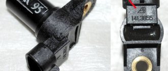
The VAZ 2110 uses two types of knock sensors. Until 2003, a single-contact resonant DD was installed. Since 2002, the VAZ 2110 with an 8-valve and 16-valve engine began to use broadband knock sensors. The new and old type DDs are completely non-interchangeable, since they have different fastenings and operating principles.
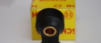
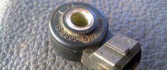
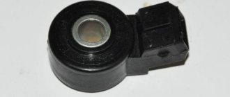
The broadband sensor has the shape of a round torus. There is a hole in its center through which the fastening bolt is inserted. On the side of the DD there is a connector that serves to connect a circuit connecting it to the electronic control unit.
The resonant knock sensor does not require a bolt to secure it to the engine. Directly on its body there is a thread with which the meter can be screwed into the seat.
There is a sensitive element inside the DD housing. It reacts to vibrations. In the case of a resonant meter, monitoring is carried out in a narrow range. Vibrations are converted by meters into an electrical signal with a certain amplitude and frequency.
The electronic control unit constantly receives DD signals. The module controls and analyzes the amplitudes and frequencies of the incoming voltage. Deviation outside the nominal range indicates the occurrence of detonation. In this case, the ECU corrects the operation of the power unit according to the established algorithm.
Eliminating detonation minimizes parasitic destructive loads that affect the cylinder-piston group. Therefore, the main purpose of the DD can be considered to quickly determine the occurrence of vibration and detonation, which is the key to increasing the service life of the VAZ 2110 engine. This is what the knock sensor is responsible for.
Final result
Finally, a few words about installing the sensor after checking it. Remember that the metal surface of the sensor must be clean and free of debris and/or rust. Clean this surface before installation. Similarly with the surface on the sensor seat on the engine housing. You also need to perform preventative cleaning. The sensor contacts can also be lubricated with WD-40 or its equivalent for preventive purposes. And instead of the traditional bolt with which the sensor is attached to the engine block, it is better to use a more reliable pin. It secures the sensor more tightly, does not loosen the fastening and does not unwind over time under the influence of vibration.
Location of the knock sensor on the VAZ 2110
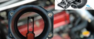
The location of the knock sensor was chosen to obtain the greatest sensitivity. To do this, it is installed directly on the power unit between the second and third cylinders. The oil dipstick can serve as a guide for determining the installation location. Also in close proximity is the air filter housing.
Removal
You can determine signs of a malfunction of the knock sensor on a VAZ 2110 by dismantling the device and performing certain manipulations with it.
But first you need to remove the device.
- The knock sensor is located on the left of the power unit, where the line of the middle of the cylinder blocks is located. You will see an air filter in close proximity to it. Many people focus on this when searching for a sensor.
- De-energize the vehicle by removing the terminal from the battery.
- Disconnect the contacts from the sensor and the wiring block. A special lock will allow you to do this if you press it.
- Now unscrew the nut securing the device.
- All that remains is to remove it from the pin.
Sensor cost
The original resonant sensor produced by Lada has article number 21120385501001. Its price is 800-1300 rubles. A good analogue for the original is General Motors 21120-3855010-01. Its cost is in the range of 1600-1800 rubles.
The wideband original knock sensor of the VAZ 2110 has article number 18.3855. Its price is 300-330 rubles. You can see good analogues in the table below.
Table - Good analogues of the original knock sensor 18.3855 VAZ 2110
| Name | vendor code | Cost, rubles |
| Coolant temperature sensor 330082 ERA | 330082 | From 300 |
| Original temperature sensor from AvtoVAZ | UK193 | From 350 |
| Luzar | LS0101 | From 150 |
| PATRON | PE13059 | From 150 |
Methods for checking a knock sensor
If there are signs of a malfunction of the knock sensor, then first of all you need to check the error log in the on-board computer. About DD malfunction they say:
- code 0325, indicates an open circuit in the sensor circuit;
- code 0326 or 0327, reports low signal level;
- code 0328, the amplitude of the voltage coming from the sensor is too high.
You can indirectly check the DD by checking the resistance with a multimeter. For a working sensor it ranges from 1 to 10 MOhm.
You should also check the voltage with a multimeter. To do this, the probes are connected to the contacts, and light blows are applied to the working surface of the DD with a bolt or rod. If there are no voltage surges, the sensor needs to be replaced.
How to check functionality?
If error code 34 appears on the display, this indicates a sensor malfunction. It is possible to check whether it is still operational or whether it needs immediate replacement. Having completely reset the self-diagnosis results, you need to drive a couple of kilometers and turn on the self-diagnosis system again.
If a new check shows an error again, then replacement is still necessary. If the error is not displayed, then you can still operate the old device. But since code 34 was still displayed earlier, it’s worth checking the connection for a break, that is, carefully inspect the wires, contacts, tighten them, clean them, and you’ll see that replacement won’t be needed.
Self-replacement of sensor 21120385501001 on a VAZ 2110
Replacement of the resonance sensor is carried out according to the instructions below
- Install a new sensor, tightening to a torque of 20 Nm.
- Connect the connector.
Replacing knock sensor 18.3855 on a VAZ 2110
Instructions for replacing the wideband knock sensor are provided.
- Press the latch and disconnect the terminal.
- Unscrew the DD fastening bolt.
- Install a new DD by tightening the fastening bolt with a tightening torque of 25 Nm.
- Connect the terminal block.
In passenger cars, engine and chassis faults are monitored, corrected and diagnosed using an electronic control unit. All machine performance indicators are measured by sensors, in particular a knock sensor.
Messages 11
1 Topic by sektor_0986 2014-03-06 09:20:44
- sector_0986
- Experienced
- Inactive
- From: Astana
- Registration: 2014-02-08
- Messages: 327 Thanks : 77
- Car: VAZ-2112
Topic: Resolved: Connecting the knock sensor
Hi all! A colleague went for diagnostics, showed a break in the DD circuit, and they actually looked and it was broken, but it was connected in an unknown way, the only thing left connected was the wire braid, they looked at mine, there the braid was completely cut off, only 2 wires go into the chip! So how should it be, tell me! VAZ 2112 8kl, 2004 without an oxygen sensor, but I have a 2002 and it is there!
2 Reply from Admin 2014-03-06 11:14:47
- Admin
- Administrator
- Inactive
- Registration: 2012-02-20
- Messages: 3,257 Thanks : 624
Re: Resolved: Connecting a knock sensor
3 Reply from igorek 2014-03-06 11:23:24 (2014-03-06 11:25:18 edited by igorek)
- igorek
- Brother-in-law
- Inactive
- From: Bryansk region g Starodub
- Registration: 2013-05-05
- Messages: 416 Thanks : 191
- Car: VAZ-21102 1.5i-8V Bosch MP7.0H
Re: Resolved: Connecting a knock sensor
Admin , as I understand it sektor_0986 means there should be a screen for the knock sensor wire? in the harness to the sensor or not, or simply 2 wires go in a braid, i.e. in a corrugation.
Added: 2014-03-06 12:23:24
sektor_0986 , yes it should be filmed if this is what we are talking about and I understand correctly
4 Reply from sektor_0986 2014-03-06 11:44:17
- sector_0986
- Experienced
- Inactive
- From: Astana
- Registration: 2014-02-08
- Messages: 327 Thanks : 77
- Car: VAZ-2112
Knock sensor - purpose
The controller responsible for regulating the ignition timing by reacting to fuel combustion is called a knock sensor. Its work is aimed at ensuring traffic safety and preventing emergency situations caused by unsystematic processes in the fuel tank. This is what the VAZ 2110 knock sensor does - it prevents troubles associated with the presence of a detonating air-fuel mixture in the engine. In a state of optimal performance, the device exists in a sleeping state. In a situation where detonation occurs, it determines its level and sends the value to the computer. There the advance angle decreases. Until the problem is resolved, correction continues.
Detonation is an out-of-system, uncontrolled processing of fuel and lubricants in the combustion chamber. The reasons for its occurrence: low-quality gasoline, incorrect advance angle, incorrect operation of spark plugs.
Optimal operation of the knock sensor protects the engine from overheating, promotes economical oil and gasoline consumption, and generates the necessary strength and power indicators.
If the knock sensor fails, the machine goes into safe mode, which reduces engine power and increases costs by increasing fuel consumption.
Signs of malfunction of the DMVR
Mass air flow sensor design
Signs of a malfunctioning mass air flow sensor can be direct or indirect. Let's consider all possible options:
- Check Engine light on the dashboard. In most cases, the CHECK indicator lights up due to the failure of one of the sensors, so you need to connect to the ECU to accurately determine the fault.
- A drop in power is only an indirect sign, since there may be another reason for this malfunction.
- Increased fuel consumption. Of course, everything can be attributed to the fuel pump, but the fuel pressure sensor must also be checked. About standard fuel consumption indicators here.
- Reduced acceleration dynamics. An incorrect amount of air mixture that enters the combustion chambers produces a poor ignition mixture, which in turn does not allow the car to accelerate normally and leads to jerking when the gas pedal is sharply pressed.
- Poor start-up or inability to start. A rich or lean fuel mixture cannot detonate normally, which will lead to just such problems. It is also possible that fuel will not burn through and there will be popping noises in the muffler.
- Floating idle speed. Different amounts of air entering the fuel mixture will have an effect when the speed will either decrease or increase.
To accurately determine the malfunction of the DMVR sensor, it is necessary to diagnose it.
How to check the MAF sensor?
The mass air flow sensor is checked using a multimeter
The mass air flow sensor is quite easy to check. For diagnostics you will need a multimeter.
- We disconnect the chips from the sensor power supply and insert the probes of the measuring device.
We connect the probes of the measuring device: red to yellow, and black to green (to sensor ground).
Voltage readings of a working and faulty sensor
- 1.01-1.02 - readings of the new sensor, everything is normal.
- 1.02-1.03 - there is wear, but the parameters are within normal limits.
- 1.03-1.04 - the parameters are working, but there is already wear.
- 1.04-1.05 - critical parameters, get ready for replacement, if you have the money, then we change it. Fuel consumption may be reduced.
- 1.05 and higher - the mass air flow sensor is not working.
Measurement using paper clips - there may be an error on the device. According to the readings, it is clear that the sensor “ordered to live long”
The second way to check the performance of the mass air flow sensor is to disconnect the power from it and drive a few kilometers. If engine performance has improved, then the problem is in the mass air flow sensor.
Internal structure and specifics of DD
The sensor is reliable because it consists of a monolithic material of the same name, which forms a system of interaction between a specific plate and a piezoelectric element. This part resonates with mechanical vibrations of the required frequency. They are interconnected with the same frequency that occurs during fuel processing.
The resulting current with minivolts of voltage is tracked in metrics and sent to the computer. Based on this value, the electronics adjusts the ignition timing, increasing or decreasing it. This neutralizes the consequences of uncontrolled detonation of low-quality fuel and lubricants.
What are the symptoms of a broken knock sensor?
Separated from the entire system, the controller itself is reliable and rarely subject to mechanical damage. Its work is influenced by a number of indirect factors.
A decrease in its functionality may be suspected in the following cases:
- engine slowdown;
- increasing speed at minimum speeds;
- when the car has problems accelerating;
- if fuel consumption has increased compared to normal levels;
- with uncharacteristic engine knocking and spontaneous jerks (engine trouble).
Code indicator 34 is a signal of DD failure. The on-board computer sometimes makes mistakes; you can check the validity of its readings like this. To confirm, reset the self-diagnosis, drive several kilometers, and if the error readings disappear, it means the sensor terminals are loose or oxidized while driving.
Error 325 indicates a break in the knock sensor of the VAZ 2120, sometimes under this sensor fault code, the ECU stores the location of the throttle valve. To verify this, find in the menu the voltage value in the sensor of interest; if there is a problem with the damper sensor, the indicator in the menu will jump, but for the DD it will remain static.
Device diagnostics
To be sure that the 2110/2112 knock sensor is faulty, it is worth checking it. This is done with a multimeter.
After all, you should understand that not in all cases the knock sensor will need to be replaced. In some cases, cleaning it will help. Sometimes other faults are detected that do not relate to the device itself. For example, an open circuit (network break). But in this case, the working connection diagram is subject to diagnosis.
If you don’t know how to check the device, then just follow the steps presented:
- Turn on the multimeter.
- Connect the wires to the two contacts of the broadband sensor. But there is a small note here: if we are talking about the resonant type, then the negative wire must be closed on the body, but the positive wire is in the center of the sensor.
- Take a screwdriver or any other metal object and start making small impacts on the sensor. But we’ll look at what this affects a little lower.
The thing is that, based on the force of the blows applied, the values on the measuring device will gradually change. They should fluctuate between 40–200 mV. This is the norm, which corresponds to the fact that the device is in good condition. But any serious damage to it will be reflected on the multimeter screen as a zero value.
Note that checking the knock sensor does not end there. Now you will need to identify the cause of the problem. Moreover, you need to look for it in the wires. In some cases, you may only need to replace the pad. The thing is that it is the one that is most exposed to the environment, which leads to corrosion on the contacts.
If you are interested in the question of how to diagnose an 8-valve injector, then you should note that in this case the process is more labor-intensive. The thing is that sometimes you need to spend extra time to remove it.
- Dismantle the device.
- Set the multimeter to measure the applied voltage at about 200 mV.
- Place one probe on the connector of the device, and the second on the opposite connector.
- Start tapping with a screwdriver, as you did in the previous case. But focus your attention on the force of the blow, since the stronger it is, the higher the signal level should be.
- Finally, check the resistance of the piezoelectric element.
In general, the VAZ 2110 8-valve injector sensor breaks down extremely rarely. The most common reason for the absence of a signal on the ECU is a break in the connection circuit.
If this device is seriously damaged, you should consider purchasing a new one. But you definitely need to familiarize yourself with how to replace the knock sensor, because installing it incorrectly can lead to the problem not being resolved.
Sources of DD failure
One of the main reasons is an open circuit, for this they check the terminals, then the wires ring, and when the engine operates more than 3000 rpm, self-diagnosis is activated.
If the electrical circuit is OK, you need to look for the problem in the controller itself. To dismantle the VAZ 2110 knock sensor (its location is problematic, between the cylinders) of the old model (resonant, single-contact), you need a socket wrench No. 13. For the new model of the sensor (broadband, two-contact), a key of 22 is required.
Messages 11
1 Topic by sektor_0986 2014-03-06 09:20:44
- sector_0986
- Experienced
- Inactive
- From: Astana
- Registration: 2014-02-08
- Messages: 327 Thanks : 77
- Car: VAZ-2112
Topic: Resolved: Connecting the knock sensor
Hi all! A colleague went for diagnostics, showed a break in the DD circuit, and they actually looked and it was broken, but it was connected in an unknown way, the only thing left connected was the wire braid, they looked at mine, there the braid was completely cut off, only 2 wires go into the chip! So how should it be, tell me! VAZ 2112 8kl, 2004 without an oxygen sensor, but I have a 2002 and it is there!
2 Reply from Admin 2014-03-06 11:14:47
- Admin
- Administrator
- Inactive
- Registration: 2012-02-20
- Messages: 3,257 Thanks : 624
Re: Resolved: Connecting a knock sensor
3 Reply from igorek 2014-03-06 11:23:24 (2014-03-06 11:25:18 edited by igorek)
- igorek
- Brother-in-law
- Inactive
- From: Bryansk region g Starodub
- Registration: 2013-05-05
- Messages: 416 Thanks : 191
- Car: VAZ-21102 1.5i-8V Bosch MP7.0H
Re: Resolved: Connecting a knock sensor
Admin , as I understand it sektor_0986 means there should be a screen for the knock sensor wire? in the harness to the sensor or not, or simply 2 wires go in a braid, i.e. in a corrugation.
Added: 2014-03-06 12:23:24
sektor_0986 , yes it should be filmed if this is what we are talking about and I understand correctly
4 Reply from sektor_0986 2014-03-06 11:44:17
- sector_0986
- Experienced
- Inactive
- From: Astana
- Registration: 2014-02-08
- Messages: 327 Thanks : 77
- Car: VAZ-2112
Re: Resolved: Connecting a knock sensor
igorek, yes, you are right, I mean the braiding of the dd connection cable, how exactly it should be connected. Like on the link?? It's right. Then why is the braid generally folded back on my car?
5 Reply from igorek 2014-03-06 11:48:50 (2014-03-06 11:59:40 edited by igorek)
- igorek
- Brother-in-law
- Inactive
- From: Bryansk region g Starodub
- Registration: 2013-05-05
- Messages: 416 Thanks : 191
- Car: VAZ-21102 1.5i-8V Bosch MP7.0H
Re: Resolved: Connecting a knock sensor
sektor_0986 , reason unknown. The previous owner probably did something clever, connect everything as it should be!
6 Reply from sektor_0986 2014-03-06 13:13:19
- sector_0986
- Experienced
- Inactive
- From: Astana
- Registration: 2014-02-08
- Messages: 327 Thanks : 77
- Car: VAZ-2112
Re: Resolved: Connecting a knock sensor
So the fact of the matter is that I don’t know how it should be. I tried two schemes and there was no result. how dd should be connected.
7 Reply from igorek 2014-03-06 13:30:43
- igorek
- Brother-in-law
- Inactive
- From: Bryansk region g Starodub
- Registration: 2013-05-05
- Messages: 416 Thanks : 191
- Car: VAZ-21102 1.5i-8V Bosch MP7.0H
Re: Resolved: Connecting a knock sensor
sektor_0986 , as in the diagram it should be, even if you connect everything as possible, you won’t feel any difference due to the fact that it’s a wire screen.
Shielding performs the following functions: - protects against mutual parasitic interference of blocks inside the device - protects these devices from interference from any other devices; - Protects other devices from interference from this device.
Source
List of errors associated with DD from the on-board computer
The cause of the failure can be found out by analyzing the error signal on the console:
- 0325 indicates a break in the DD circuit, which can be eliminated by cleaning the sensor connectors from oxidation and ringing the wiring;
- 0325 may also indicate that the timing belt is shifted by one tooth; it is necessary to check that the belt is installed correctly;
- 0326, 0327 indicates a low controller signal, requires checking the connectors, securing the nut with a force of 10-23 Nm, the action is performed with a special torque wrench.
- 0328 - the control signal is higher than normal, may appear when the electrical circuit is broken, a piercing element, or a faulty DD.
Common faults
Before changing the device on the 8-valve motor, you need to take time to diagnose it; to do this, first check the power wiring. As practice shows, the phase sensor error is often caused by oxidation of the contacts; if this is the case, then they only need to be cleaned. Typically, this regulator is very reliable; signs of malfunction in its operation rarely appear.
But if the controller on a motor with 8 or 16 valves breaks down, you can either check it with a computer or analyze the signs of a malfunction:
- drop in power of an 8- or 16-valve engine;
- From time to time, the Ckeck Engine indicator may appear on the dashboard, especially when increasing power, at the very beginning of driving, or when driving uphill;
- signs of malfunction also include engine tripping - when driving at low speeds, the engine begins to shake;
- car self-diagnosis will also show errors 0325, 0326, 0327, 0328, which indicate problems in the electrical circuit of the device.
Old and new sensors
The old-style VAZ 2110 resonant knock sensor monitors vibrations of a limited frequency spectrum, has the smallest indicator error, and high accuracy. It is equipped with VAZ 2110 cars from 2002-2003. This is a single contact controller.
The wideband controller reads the signal of all frequencies that arise during movement, its readings are approximate due to the wide range of received signals. From an electrical point of view, it is a two-pin device.
The sensors are not interchangeable, so purchase and installation must match the original part sample.
The controllers are screwed into the cylinder block on the left. Replacing it takes a few minutes.
Replacing the knock sensor
Replacing a resonant DD with a broadband one is possible provided that certain operations are performed:
- production and purchase of additional parts (microphone cable (shielded), sensor mounting pin, sensor connector; new chip for the ECU.
- installation of the cable to the 1st contact of the connector, the screen to the 2nd contact;
- pulling the cable to the ECU to pin 11 (pin DD);
- pulling the screen to ECU pin 30 (sensor ground);
- removing the ECU, disassembling, removing the chip (the chip is not soldered);
- installation of a new w27c512-45 chip;
- Firmware download (m1d13a64) from an on-board computer repair company.
- installing the chip in the ECU, returning the ECU to its place.