Along with other options for improving the units and systems of the VAZ 2107, a non-contact (electronic) ignition system (BSI) is being considered instead of the standard one. This modernization makes it possible to provide stable increased voltage on the spark plugs, which, in turn, makes it easier to start the engine and increases spark energy.
Installing and adjusting a contactless ignition system is quite a difficult task, so if you do not have sufficient skills in working with automotive electronics, it is better to entrust this work to specialists. If you feel that you are able to install the BSZ kit on a VAZ 2107 yourself, then carefully study these instructions and get to work.
To work you will need the following set of tools and materials:
- Key to 8;
- Key for 10;
- Key to 13;
- Phillips screwdriver;
- Two self-tapping screws;
- Drill with a drill of the same diameter as the self-tapping screws;
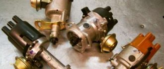
Naturally, in addition to all this, an electronic non-contact ignition system must be purchased, or rather a set of its components: a coil, a switch, a distributor and wires for connecting all the elements together.
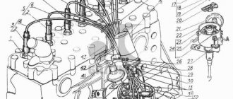
Below is a schematic diagram according to which the contactless ignition system for the VAZ 2107 is connected.
Distributor
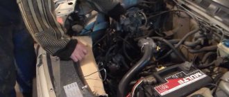
The sequence of work that must be performed in order to install a set of new parts on a VAZ 2107 does not make much difference. Therefore, we can start by replacing the distributor. Remove the distributor cover to access the slider. To simplify the task of further adjusting the BSZ, you should immediately perform some preparatory measures: installing the distributor slider in a position that will be easy to repeat when installing a new distributor; mark on the block opposite the middle mark on the distributor scale, which is used to adjust the ignition.
Using a 13mm wrench, completely unscrew the nut securing the distributor and then remove it. Disconnect the high voltage wire connecting the ignition coil and the distributor. We install a new non-contact sensor distributor, and you need to set the slider so that it matches the position of the old one. The body of the new distributor needs to be aligned according to the marks, the middle one opposite the one previously left on the engine body. We put on the distributor cover and a set of high voltage wires.
Prerequisites for failure
Please note that the engine control system malfunction warning lamp, located on the device panel in the signaling unit, is the first indicator of deviations in the operation of the VAZ 2107, where an injector is used. Some modifications of the VAZ 2107 provide for the location of the warning lamp on the upper insert of the radio panel. By starting the ignition, a system malfunction is tested, which means the lamp lights up and goes out after the engine starts.
A prerequisite for diagnosing the ignition system is that the lamp does not go out when the engine is running.
By starting the ignition, a system malfunction is tested, which means the lamp lights up and goes out after the engine starts. A prerequisite for diagnosing the ignition system is that the lamp does not go out while the engine is running.
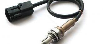
In situations where there is a malfunction, VAZ 2107 owners replace the spark plugs. Old factory spark plugs are usually replaced with iridium spark plugs from NGK or Denzo. Do not forget that only those spark plugs that are designed for the appropriate type of injection are suitable here.
The type of ignition system is no less important in determining the parameters of the spark plug. Often such manipulation does not provide much improvement (plugs have a fairly long service life), so the non-contact ignition system undergoes a full diagnosis.
Do you want to know more about how to install
valve timing according to marks on VAZ 2101-
VAZ 2107
? And so.
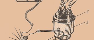
Coil
Next, you need to replace the ignition coil. Using a size 8 wrench, unscrew the nuts securing the wires to the coil contacts. Using a 10mm wrench, unscrew the mount of the coil to the body. Installing a new coil requires special attention - you should take into account the possible discrepancy between the locations of contacts “B” and “K”. For convenience, you can rotate the new electronic coil relative to the fastener, thereby placing the contacts in the same way as on the old one.
Having secured the coil, we connect old wires to its contacts (usually one blue, the other brown), and new ones, with connectors for connecting to the distributor and switch. They usually have the same colors as the standard ones. Typically, in a VAZ 2107, brown wires are connected to contact “K”, and blue wires are connected to “B”. It remains to connect the high-voltage wire that connects the coil and the distributor.
General tips for connecting high-voltage wires.
Checking high-voltage wires. To check the wires, you will need a multimeter tester. Check the resistance of the wires - it should be no more than 20 KOhms (in practice, the longest wire of cylinder 1 has a resistance of up to 10 KOhms). If the wire resistance is more than 20 Kom, it must be replaced. Carefully inspect the wires for chafing on parts of the motor or other wires. In case of significant abrasion, replace the wire. In case of minor abrasion, it is possible to lay the wire so that it does not rub and fix it in this position.
Laying wires. Do not try to connect the wires in a bundle. Disassemble the wiring harnesses, release the wires from the plastic holders. Connect the high-voltage leads to the corresponding cylinder spark plugs. Lay the wires so that they do not rub against each other, engine parts, or hoses. Avoid sharp bends and tension on the wires. After connecting all the wires, secure them into the bundle with special comb holders included in the delivery kit.
The procedure for connecting I/O wires to a VAZ carburetor (2108, 2109, 21099)
The central wire from the distributor cover always goes to the ignition coil (bobbin).
The outlet of the distributor cover, which faces towards the front of the car, is connected to the first cylinder.
The outlet of the distributor cap, looking down, is connected to the third cylinder.
The outlet of the distributor cap, looking rearward, is connected to the fourth cylinder.
The outlet of the distributor cap, looking up, is connected to the second cylinder.
The procedure for connecting high-voltage wires to a VAZ Classic, Niva with a carburetor and distributor.
Central wire from the ignition coil (bobbin)
1 cylinder - above the vacuum corrector. Next, clockwise, the order is 1-3-4-2.
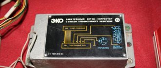
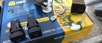
Switch
The last element in the circuit, the presence of which is required by a contactless electronic ignition system, is a switch. The ideal place in which it can be installed in a VAZ 2107 is between the washer reservoir and the left headlight. There is a flat area on which we will install the switch, with the radiator facing the body. Having leaned the switch, we mark the places for drilling holes in the body, through which we fasten it with self-tapping screws; in this case, you need to screw the black (neutral) wire from the connection block under one of the screws.
After completing all the work described above, you should once again carefully check the connection of the wires according to the circuit diagram. If everything is done correctly, you can try to start the engine. Usually there are no problems with this; all that remains is to adjust the ignition to ensure the most efficient operation of the engine.
The key to high-quality circuit testing
Non-contact ignition system checks for short circuits
First, pay attention to the coil winding. To get started, connect a multimeter, which determines the resistance value
There is a recommendation regarding the lubrication of the tip of a high-voltage wire: a special product for the VAZ 2107 or technical petroleum jelly is used here.
The coil itself is diagnosed as follows:
- the module is disconnected from the tips;
- one terminal of the device is connected to the central contact, which has a coil;
- the other terminal of the device is connected to ground.
If the display of the infinity device implies that there is no short circuit, then the coil is in order
Important: unchanged display indicators when ringing the circuit will indicate infinity
Checking the primary ignition circuit involves installing a multimeter to its left and right contacts, which are assigned the ignition function. This setting of the ohmmeter should cause a change in readings. If this is not observed, you can prepare not only to replace the coil, but the entire device. Here they focus on the norm, which is 3-3.5 ohms.
The process of checking the secondary windings of the module includes:
Disconnecting wire tips from it. Level position in front of you. Installing the module to the right outputs of the upper and lower locations
We focus on the indicators that the device displays in seconds. The previous manipulation is carried out similarly with the left outputs of the upper and lower locations. Here we focus on the indicator, the value of which will be no less than 7 Ohms
Recommendation: if at least one coil does not meet the specified indicator, the module as a whole must be replaced, otherwise it will not be possible to avoid a malfunction of the system with a VAZ 2107 where an injector is used
Here we focus on an indicator whose value will be no less than 7 ohms. Recommendation: if at least one coil does not meet the specified indicator, the module as a whole must be replaced, otherwise a malfunction of the system with VAZ will be avoided 2107
where
an injector
, it will not work.
Adjustment
Without any instruments, you can set the ignition timing experimentally. When warmed up to operating temperature (80-90 degrees), when driving at a speed of 40 km/h, you need to switch to speed 4 and depress the gas pedal. If the electronic contactless ignition was set correctly, a short-term detonation should occur, after which the engine should begin to gradually gain speed. If valve knocking occurs, you need to turn the distributor clockwise by about a degree. The operation is repeated until the knocking stops. If, during the check, a dip in engine speed appears, the distributor is turned in the opposite direction.
In addition to adjusting the ignition timing, the new system may require carburetor adjustment. The VAZ 2107 carburetor has two adjusting screws - quantity and quality. The adjustment is carried out as follows:
- By rotating the quantity screw, the engine speed is equal to 1200-1300. Next, use the quality adjustment screw to set the maximum speed.
- Repeat the operation described in paragraph 1 until, at a speed of 1200-1300, the quality adjustment screw is set to the position corresponding to the maximum engine speed.
When installing the BSZ, experts recommend performing not only adjustments, but also cleaning and purging of the carburetor in order to see the real effect of this modernization.
For normal operation of a gasoline internal combustion engine, the formation of a spark is necessary in a timely manner. For this purpose, a special device is used to ensure its appearance when the piston is in the TDC (top dead center) position, and sparking occurs in different cylinders at different times. Such a device is called a breaker-distributor, or in other words, a distributor. Without it, not a single gasoline internal combustion engine operates, and for many years it was an integral part of any ignition system, including VAZ 2109, 2106, 2107, 2108.
Setting the ignition timing with advance
This setup is completely easy to do. Even a beginner can cope with this task. To do this, prepare a 13 mm wrench and a special 38 mm crankshaft wrench in advance.
If your car is started, be sure to turn off the engine, since you can only turn on the ignition when the engine is turned off. First, the piston of the first cylinder is installed at the top dead center of the compression stroke, that is, in the ignition position. Before doing this, remove the candles and plug the hole from them with cotton.
You need to align the mark on the crankshaft and the front engine cover. To do this, use a wrench to start turning the crankshaft clockwise. During this action, the air compressed there should push out the cotton wool, thereby indicating the compression stroke. Continue turning the shaft slowly until the marks on the timing belt pulley and cover line up.
Please note that there are 3 marks on the cover:
- The first indicates ignition advance by 10º;
- the second – by 5 º;
- the third is equal to zero.
Since a VAZ 2107 engine with a carburetor runs on 92 or 95 gasoline, we need to set the ignition for these types of fuel. That is why you should select the second mark, which will indicate an ignition advance of 5º.
Once the required parameters match, put the spark plugs in place and remove the wires. The system is ready for use.
Why do you need a distributor?
The ignition system is a critical part of a gasoline engine. The operation of the latter is based on the timely combustion of the fuel-air mixture (FA), for which purpose a high-voltage voltage is specially generated, which is then supplied to the spark plugs. A spark is formed on them, causing combustion of the fuel assemblies, as a result of which the engine performs useful work. This is roughly how you can briefly describe the operating principle of a gasoline internal combustion engine.
All these processes require a distributor. If we evaluate its role during the operation of the ignition, it should be noted that it:
- initiates the onset of sparking due to the opening of the breaker contacts (in more modern car models, for example, VAZ 2109, 2106, 2107, 2108 of the last years of production, a Hall sensor is used for these purposes);
- directs the high voltage generated in the ignition coil to the desired spark plug;
- changes the beginning of the moment of spark formation depending on the driving modes and the fuel used, for which vacuum centrifugal regulators are used;
- provides accumulation and discharge of energy in the reel.
About the ignition system in detail
The ignition system of a gasoline internal combustion engine “breathes” due to spark formation on the SZ elements, which ignite the mixture in the combustion chamber. Obviously, the efficiency of the fuel combustion process, the functioning of the engine as a whole, etc. directly depend on the timing of ignition. For this reason, the ignition must be set to the most optimal position for normal operation.
Most modern cars are equipped with electronic ignitions that do not require any adjustments. However, for the normal functioning of cars with a carburetor ignition system equipped with a 4-stroke internal combustion engine, adjustment is required. It is thanks to this that timely sparking is guaranteed.
Correct adjustment of the distributor
The first sign that something wrong is going on with the ignition system is characteristic knocks and noises while the car is driving.
A 4-stroke internal combustion engine operates according to the following scheme:
- First, fuel is injected.
- Then the compression stroke occurs.
- A working stroke is in progress, during which a spark is generated that ignites the mixture.
- Finally, the last step is the release of the working.
Ignition, to be more precise, occurs not during the working moment, but at the border of the compression stroke and the working stroke. At this very moment, the SZ produces a spark that ignites the fuel mixture.
Important point. The SZ is required to produce a spark at the moment when the motor piston almost reaches a position called TDC.
Setting the ignition on the distributor
It happens that the moment of operation of the SZ becomes a little off as time passes, which entails a decrease in the time of effective spark action. The time interval between reaching TDC and ignition of the fuel is called ignition timing. Its value is determined by a numbered scale marked on the crankshaft flywheel.
Operating principle of the distributor
In many ways, the operating principle of the distributor remained unchanged for many years. In VAZ cars, such as VAZ 2109, 2106, 2107, 2108, an ignition system of this type was used almost until the end of the last century.
The basis of the work is the connection of the distributor with the engine crankshaft . When the piston in the first cylinder takes the position corresponding to TDC, the breaker contacts open, a high voltage appears in the ignition coil, directed through a slider located in the distributor cover to the spark plug of the first cylinder.
There the combustion of the fuel assembly occurs, and the crankshaft continues to rotate. In addition to moving the pistons, it causes the breaker cam to rotate. When in another cylinder another piston occupies a position corresponding to TDC, at this moment the breaker contacts in the distributor open again, and a high-voltage voltage is generated in the ignition coil and supplied to the desired spark plug.
This combined rotation of the crankshaft, the breaker cam and the distributor slider ensures that a spark appears where and when needed. However, this does not cover all aspects of how the distributor works. To understand its operation, it is necessary to touch upon such concepts as the angle of the closed state of contacts (UZSK) and the ignition timing angle (IAF)
A concept such as UZSK characterizes the time when the breaker contacts are closed. In essence, this is an indirect characteristic of the accumulation of energy in the coil after the completion of spark formation. UZSK directly affects the amount of energy spent on sparking and, accordingly, on engine operation.
In cases where the distance between the contacts is small, the coil will not accumulate the necessary energy and the spark energy will be low, which will lead to interruptions in the operation of the motor. A large gap also leads to interruptions, since the contact breaking time is reduced and the coil does not have time to fully discharge.
Each ignition system has its own optimal UZSK, to ensure which, if necessary, the distributor must be checked and adjusted.
This concept concerns the moment of ignition of a fuel assembly. The fact is that its combustion does not occur instantly, and often, to ensure optimal conditions for such a process, it must begin earlier than the piston reaches the TDC position. The OZ characterizes the time by which the appearance of a spark precedes the appearance of the piston in the TDC position.
It is constantly changing, and its value completely depends on the operation of the motor under specific conditions, i.e. depending on the load, vehicle speed, quality and type of fuel used. To ensure optimal combustion of the fuel assembly, the distributor contains a centrifugal regulator and is also connected to a vacuum regulator.
In what cases is ignition installation necessary?
There are several symptoms by which a car owner can determine that it is necessary to adjust and set the ignition breaker:
- Inability to start the engine.
- Increased gasoline consumption. Of course, this may be due to the need to adjust the carburetor, but this also happens. For example, if the ignition is set later, the dynamics of the car will be low, and in order to accelerate normally, the engine needs more air-fuel mixture.
- The appearance of shots in the silencer. If the explosion follows, it will take some time for the gases to expand. In the event that the piston reaches BDC, the exhaust stroke will be next, which means that a certain part of the fuel will be transferred to the exhaust system. Accordingly, pops will appear as a result.
- The power unit began to operate noisier. and you will need to install 2106 correctly in case of shaking and tripping of the engine. The upward piston makes the operation of the power unit more rigid, and the explosion of the mixture will occur towards it.
Setting the ignition to "six"
What does the distributor consist of?
A device such as a distributor includes a large number of different parts. It is not the purpose of this material to consider their purpose, but you can see what components the distributor consists of in the figure below
As can be seen from the figure, the distributor consists of several independent units. And if the purpose and operating principle of the voltage distributor unit are simple and clear, then you can familiarize yourself with the work of others in more detail. However, it is advisable to check the condition of the high-voltage distributor and slider each time the car is serviced.
Centrifugal regulator
Such a device determines the moment when fuel assemblies begin to burn in the engine cylinders. As already noted, a spark initially appears when the piston reaches the TDC position, and it is at this moment that the distributor is initially adjusted. However, two points need to be taken into account:
- Combustion of fuel assemblies occurs at a constant speed, starting from the spark plug and then spreading further throughout the volume of the cylinder. Combustion does not occur instantly, and the greatest efficiency of a gasoline internal combustion engine is achieved when the piston has passed TDC and reached BDC (bottom dead center).
- When the engine is running, the crankshaft speed changes; increasing it reduces the time required for efficient combustion of the fuel assembly.
To eliminate this contradiction, the concept of CVD is introduced, which implies the start of fuel combustion before the piston reaches TDC. The device that ensures the formation of the UOZ is a centrifugal regulator, shown in the figure; it consists of weights connected by springs and a plate.
Its operating principle is based on centrifugal force; an increase in crankshaft speed causes the weights to diverge, and through the plate - a change in the position of the cam and the runner. This will cause the contacts to open sooner and will also cause high voltage and spark to occur earlier. The fuel assembly will ignite when the piston position has not reached TDC, which will ensure its efficient combustion.
Distributors from different manufacturers have a similar adjustment of the fuel assembly ignition moment, including in VAZ 2109, 2106, 2107, 2108.
Vacuum regulator
Such a device is designed to change the SOP when the engine load changes, determined by the position of the throttle valve. The following figure will help you understand how this is done:
The vacuum regulator is a closed cavity separated by a diaphragm. One of the cavities is connected to the carburetor. The vacuum created in it, depending on the position of the throttle valve, causes the diaphragm to move. A change in its position is transmitted through the rod to the movable disk, which affects the position of the breaker cams, adjusts the time of its operation (earlier or later), and, accordingly, the ignition time of the fuel assembly.
Thus, the distributor, depending on the load on the engine, changes the moment of spark formation, affecting the characteristics of the engine. This adjustment is present in all VAZ 2109, 2106, 2107, 2108 cars, and the joint operation of the described regulators can ensure efficient engine operation over the entire range of loads and crankshaft speeds.
Octane corrector
This device allows you to mechanically change the OZ depending on the fuel used (octane number) or its quality. You can see the corrector in the figure below. In fact, these are two plates, one is installed on the distributor and has an arrow, the other is attached to the engine, and there are marks on it. By changing their position in relation to each other, you can mechanically set the desired ignition angle. This is required mainly when using different types of gasoline.
Replacing the starter relay
Another common problem on VAZ 2107s with a carburetor is a malfunction of the starter relay. When you turn the key in the lock, the system makes a click, but the retractor relay does not operate. Replacing the relay is very simple.
First you need to remove the starter from the relay. Unscrew the 2 bolts that secure it. Slide it to the right and take it out, turning it backwards. Unscrew the nuts securing the starter and relay.
Turn it to the side.
Remove the 2 bolts securing the relay to the starter.
Install the new one in reverse order.
If you follow these simple steps, your VAZ 2107, which has a carburetor system, will serve you for many more years.
Vehicle dynamics, fuel consumption, exhaust toxicity and starting reliability on a carburetor “seven” depend on the correct setting of the ignition timing. The outdated “contact” system requires periodic maintenance and adjustment. Ignition adjustment on a VAZ 2107 with an injection engine equipped with a contactless ignition system is not required. But owners of outdated modifications of the VAZ 2107 have to go to a service station for adjustments or perform the operation themselves. This is not difficult to do.
Contactless systems and Hall sensor in the distributor
The distributor described above is a classic version and was used for many years on all cars, including the VAZ family, such as 2109, 2106, 2107, 2108. However, as electronics developed, voltage switches began to appear in which the breaker signal was used not for switching the ignition coil, but for controlling the electronics. Later, the distributor lost its mechanical breaker and was replaced by a Hall sensor.
The Hall sensor used has a fairly simple design. Yes, it must be recalled that the Hall sensor is an element that responds to a magnetic field. Therefore, the design of the sensor using Hall elements is based on this principle. To do this, a Hall sensor is located directly on the plate, on the other side there is a permanent magnet, and between them there is a rotating metal screen in which special slots are made. When the screen blocks the field from the installed magnet, the Hall sensor has zero voltage at the output; when windows are opened instead of a solid screen, the Hall sensor generates a high voltage at the output. The distributor transmits this generated sequence of pulses to the voltage switch, and it controls the ignition coil.
Electronic ignition device
The electronic ignition circuit of the VAZ 2101, as well as the VAZ 2105, 2106, 2107 or 2109, includes a distributor with a contactless electronic sensor and a steel screen, a switch, a coil with an open magnetic circuit, spark plugs with high-voltage wires and a set of connecting wires.
The advantages of installing electronic ignition on all VAZ classics, no matter whether it is 2106 or 2107, are obvious. Practicality, stable operation, more reliable (powerful) spark generation and high-quality combustion of the mixture, durability, no problems with the contact group, easier engine starting - this is not a complete list
It must also be said about the virtually non-existent ignition breakdowns, improved car dynamics, and a slight but significant reduction in fuel consumption when using a contactless system.
The disadvantages include the rather high price of the VAZ electronic ignition and the possible failure of the Hall sensor. Well, okay, the sensor is easy to replace even on the road. Anyway, let's get started.
How to check the distributor
The most common manifestations of an ignition malfunction will be as follows:
- floating idle;
- engine that won't start;
- engine stalling while driving.
Most often, the cause of this may be the distributor. The easiest way to check the performance of the ignition, including the distributor, is as follows. To do this, unscrew the spark plug, bring it to the engine and start it, observing the appearance of a spark. If it is not there, then you need to check the functionality of the high voltage wires. If there is no spark again, then the diagnosis is clear - the distributor has failed.
In this case, you need to visually check the condition of the slider, the condition of the contacts and the distributor cover. Burnt contacts are cleaned and dust and debris are removed from the internal surfaces of the distributor. In a workshop or garage, you can check the performance of the ignition and distributor using measuring instruments and indicators.
The distributor appeared on the car almost simultaneously with the gasoline engine, and for many years remained almost unchanged, including on domestic cars of the 2109, 2106, 2107, 2108 family. And only after the advent of a modern element base, which includes the Hall sensor, gave way to contactless and then microprocessor ignition systems. » alt=»»>
Ignition malfunctions of the VAZ 2107, regardless of the type of system itself (contact or non-contact), are often associated with a distribution switch (distributor). Despite its complex electromechanical design, almost any breakdown can be fixed with your own hands.
Installation of contactless ignition on VAZ-2107 cars
The first step, of course, is to purchase a set of equipment for contactless ignition. We advise you to purchase an ignition kit only from trusted places. Do not forget to read the instructions for the purchased device
It is important that the contactless ignition kit matches the technical characteristics of your car
Pay attention to the length of the distributor shaft - it should not differ from the size of the shaft installed on your machine
The standard contactless ignition kit includes the following parts:
- coil;
- distributor;
- connecting wires;
- switching unit;
- four DVRM spark plugs;
- high-voltage wires (set).
To successfully install a contactless ignition system, you must follow a certain sequence of actions. The first step is to turn off the power to the car; to do this, remove the negative terminal from the battery. Next, we disconnect all the wires, including the main high-voltage wire, from our ignition coil. Now you can remove the distributor cover. We set the distributor slider to a certain position so as not to disturb the existing ignition settings. It is also necessary to place a mark on the engine block in order to correctly install the new distributor
Be sure to pay attention that the mark should be placed in the middle of the five slots that are located at the bottom of the distributor. After these manipulations, you can unscrew the nut and remove the old contact ignition distributor
Before directly installing the new distributor, you must remove its cover and place the slider in the same position as on the old distributor. Only after this can the distributor be inserted into the hole in the engine block. Next, align the marks and clamp the distributor body with a nut.
We reassemble: install the cover, screw it on and connect the wires. Now let's move on to the ignition coil. We disconnect and carefully remove the old coil, then install a new one in its place. We connect the second end of our central high-voltage wire to the coil, and put aside the brown wire that previously went from the distributor to the coil; we will no longer need it.
We put all high-voltage wires in their places. We connect two brown wires to the new coil - to contact “K”, and connect two blue wires to the contact marked “B”.
We decide on the place where the switch will be attached. You can install it near the washer reservoir. It is attached to the body using self-tapping screws. We connect the connector to the switch and tightly twist the wires with electrical tape.
We start the engine and adjust the operation of the contactless ignition system.
Video: “BSZ - contactless ignition system”
Ignition distributor-distributor "seven"
The distributor is used to generate pulse voltage in the low-voltage circuit of the ignition system, as well as distribute high-voltage pulses among the spark plugs. In addition, its functions include automatic adjustment of the spark advance angle.
What kind of distributors are there?
In the VAZ 2107, depending on the type of ignition system, two types of distributors can be used: contact and non-contact. In appearance they are practically no different. The difference between them lies in the device responsible for generating a pulse in the low-voltage circuit of the system. For the former, a group of contacts is responsible for this function, for the latter - an electromagnetic sensor, the operation of which is based on the Hall effect. In all other respects, the operating principle of the devices is identical.
Ignition marks VAZ 2107
When adjusting the advance angle, you must focus on the marks marked on the crankshaft pulley and on the front engine cover.
There is a notch on the engine pulley that should align with one of three marks on the cover, depending on the fuel used.
The marks on the lid are of different lengths - short, medium and long. The first corresponds to an advance angle of 10 degrees, the second - 5 degrees, the third - 0 degrees (the mixture is ignited at TDC).
High octane fuel burns faster than low octane fuel. The VAZ 2107 is designed for gasoline with an octane number of 92-95, so the optimal advance for it is 5 degrees.
Contact distributor
All models and modifications of Zhiguli were equipped with contact type distributors until the early 90s of the last century. A distributor with serial number 30.3706 was installed on the VAZ 2107.
Design of contact breaker-ignition distributor 30.3706
The contact distributor consists of the following elements:
- frame;
- rotor (shaft);
- slider (rotating contact);
- contact breaker;
- capacitor;
- centrifugal and vacuum ignition timing regulators;
- cover with main (central) and four side contacts.
Housing and shaft
The base of the device is cast from aluminum. A cermet bushing is pressed into its upper part, playing the role of a support bearing for the distributor shaft. The side of the housing is equipped with an oiler through which the bushing is lubricated in order to reduce the friction force. The lower part of the shaft (shank) has splines for connecting additional engine elements to the drive gear. With their help it is set in motion.
Runner
A slider is installed at the top of the rotor. It is made of plastic and has two contacts connected through a resistor. Their task is to receive voltage from the coil through the central electrode and transfer it to the side contacts of the distributor cap. The resistor is used to eliminate radio interference.
chopper and capacitor
The breaker mechanism includes a group of contacts and a cam with four protrusions. The contacts are fixed on a movable plate, the rotation of which is ensured by a ball bearing. To be able to adjust the gap between the contacts, one of the mounting holes is made in the form of an oval. The moving contact is located on a spring-loaded lever. The other contact is stationary. In a calm position they are closed.
The cam is the thickened part of the shaft. Its protrusions serve to actuate the moving contact. When the breaker-distributor shaft begins to rotate, the cam with one of its protrusions rests against the movable contact block, moving it to the side. Then the protrusion passes the block and the contact returns to its place. This is the simple way to close and open the low voltage circuit in the contact ignition system.
Despite the fact that the voltage on the contacts is small, when they open, a spark is still formed. In order to eliminate this phenomenon, a capacitor is installed in the breaker circuit. It is attached with a screw to the distributor body.
Centrifugal regulator
The primary adjustment of the moment of spark formation in VAZ 2107 cars is carried out by turning the entire distributor . Further adjustments are made automatically. The function of the centrifugal regulator is to change the ignition timing depending on the number of engine crankshaft revolutions.
The basis of the mechanism design is the support and drive plates. The first is soldered to a bushing that is movably fixed on the distributor shaft. It can rotate relative to the shaft with an amplitude of 15°. On top it has two axles on which weights are installed. The drive plate is mounted on the upper end of the shaft. The plates are connected to each other by two springs of different stiffness.
When engine speed increases, centrifugal force also increases. It first overcomes the resistance of a softer spring, then a stiffer one. The weights rotate on their axes and rest against the support plate with their side protrusions, causing it to rotate together with the slider to the right, thus increasing the ignition timing.
Vacuum regulator
The vacuum regulator is attached to the distributor body. Its role is to adjust the ignition angle depending on the load on the power plant. The design of the device consists of a reservoir, a membrane with a rod located in it, as well as a hose through which the regulator is connected to the primary chamber of the carburetor.
When a vacuum appears in the carburetor, it is transmitted through a hose to the reservoir of our device. A vacuum is created there. When this happens, the membrane moves the rod, and it acts on the rotating breaker plate, turning it counterclockwise, increasing the ignition timing.
Contact type distributor malfunctions and their symptoms
Taking into account the fact that the distributor is a rather complex device, it is subject to the influence of a number of negative factors that can damage the elements of its design. That is why the distributor can have a lot of malfunctions. Well, as for common device breakdowns, they include:
- electrical breakdown of the lid;
- wear of the central electrode or side contacts of the cover;
- burning of the slider contacts;
- electrical breakdown of the capacitor;
- violation of the gap between the contacts of the breaker;
- wear of the moving plate bearing.
Ignition systems for VAZ-2101-2107 cars
Contact ignition system
The contact ignition system consists of an ignition switch, an ignition coil, a distributor-breaker, spark plugs, low and high voltage wires.
Ignition distributor 30.3706
The ignition distributor converts low-voltage direct current into pulsed current and distributes high-voltage current pulses across the spark plugs. It is structurally combined with a chopper and centrifugal and vacuum ignition timing regulators.
| rice. 1 |
The distributor is installed in the front of the cylinder block on the left side.
The distributor housing is cast from aluminum alloy. Two plain bearings are pressed into the housing shank, in which the roller rotates. A breaker cam is made on the top of the roller, and a centrifugal ignition timing regulator and rotor (runner) are also mounted. When the roller rotates, the weights of the centrifugal regulator diverge under the action of centrifugal forces and rotate the tetrahedral cam of the breaker at a certain angle in the direction of rotation of the roller. In this case, the contacts open with some advance, the greater the higher the engine speed. The rotation angle is limited by the size of the groove in the rotor support plate.
| rice. 2 |
The breaker consists of a stand with a fixed contact and a movable contact with a textolite stop, which is pressed by a flat spring to the tetrahedral cam of the distributor roller. When the cam rotates, the contacts close and open. The cam is lubricated with a felt fold soaked in engine oil.
When operating a car, it is necessary to systematically check and adjust the gap between the breaker contacts.
The plate on which the breaker mechanism is mounted is mounted on a ball bearing, allowing it to rotate around the axis of the roller.
The plate is connected by a rod to the diaphragm of the vacuum ignition timing regulator. The vacuum (supplied through the hose from the rear throttle space of the carburetor) acts on the diaphragm of the vacuum regulator, and the rod rotates the breaker mechanism together with the movable plate relative to the tetrahedral cam, thereby ensuring optimal ignition timing depending on the engine load.
To reduce sparking between the contacts of the breaker, a capacitor is connected in parallel with them. It is fixed externally to the distributor housing.
The top of the distributor housing is closed with a cover with sockets for high voltage wires. A spring-loaded carbon is mounted inside the lid into its central electrode. A rotor with a contact plate (runner) distributes high voltage current to the spark plugs in accordance with the firing order of the cylinders (1 - 3 - 4 - 2). The ignition distributor shaft rotates clockwise (when viewed from above).
When adjusting the ignition timing, turning the distributor housing clockwise reduces the timing, counterclockwise increases it.
Ignition coil B-117A
The ignition coil is a step-up transformer that converts low voltage pulse current (12V) into high voltage current. The coil windings are installed in a housing made of thin galvanized steel. The housing cover is made of insulating material, has two low-voltage terminals and a socket for a high-voltage wire. The coil body is filled with transformer oil, which cools the windings.
The ignition coil is installed in the engine compartment and secured to the left mudguard of the body with two nuts.
Ignition switch
The ignition switch is a combined switch, consisting of a lock with an anti-theft device and a contact part, assembled in one housing. The switch is installed on the left side of the steering column in a special bracket and secured with two screws.
Spark plug
The spark plug ignites the working mixture in the cylinder with a spark discharge. The design of the candle is non-separable.
For a properly functioning spark plug, the color of the central electrode insulator skirt should be gray or light brown.
| rice. 3 |
The car uses spark plugs A17DVR (A17DVRM) or their analogues.
Repair of contactless distributor
To determine and eliminate the malfunction, careful diagnostics are required, which involves dismantling and disassembling the device. The only element of the distributor that can be checked without disassembling it is the capacitor. Let's start with him.
Capacitor check
As already mentioned, the capacitor serves as a kind of spark arrestor. It prevents the formation of an electric arc between the breaker contacts at the moment they open. To check its functionality, you must perform the following steps:
- Disconnect the low voltage wire connecting the coil and distributor.
- Disconnect the capacitor wire from the distributor.
- Connect these two wires to a regular twelve-volt car lamp.
- Turn on the ignition. If the lamp lights up, the capacitor is broken.
- Replace the capacitor, check how the engine works.
Removing the distributor from the engine
The distributor is installed in the engine cylinder block on the left side. It is fixed on a special bracket with one nut. To dismantle the device you must:
- Disconnect the “-” wire from the battery terminal.
- Unfasten the two latches securing the breaker-distributor cover to the housing.
- Disconnect all armor wires from the cover.
Disassembling the distributor and replacing faulty elements
The functionality of each part of the device can be determined already at the stage of disassembling it. To do this you need:
- Carefully inspect the distributor cover from the outside and inside. Particular attention should be paid to the central electrode (carbon) and side contacts. If wear, damage, or severe burning is detected, the cover must be replaced.
Video: disassembling and repairing a contact distributor
Installation of the distributor and setting the ignition timing
The distributor is assembled after replacing the faulty parts in the reverse order. There is no need to install the cover to the device at this stage. To install the distributor and set the correct ignition timing, you should:
- Engage neutral gear.
- Install the distributor into its seat, not forgetting the O-ring.
Video: setting ignition timing
Setting the angle of the closed state of the contacts
The stability of the engine operation depends on how correctly the angle of the closed state of the contacts (the gap between the contacts) is inserted. To configure it you need:
- Using a “38” wrench placed on the crankshaft pulley mounting nut, rotate the shaft until the moving contact lever stops on one of the cam protrusions.
After carrying out this work, you can install the cover on the distributor body, connect the high-voltage wires and try to start the engine.
Instructions for setting up the ignition
The cause of engine overheating and loss of power may be late ignition. This may manifest itself as popping noises in the intake manifold. Therefore, you need to know how to install the ignition correctly (the author of the video is Nail Poroshin).
Installation is carried out according to the marks as follows:
- First, you need to set the piston on the first cylinder to TDC and align the installation indicator mark with the mark on the crankshaft pulley.
- Next, the crankshaft must be turned counterclockwise until the marks 9 on the pointer coincide with the marks on its pulley.
- Then you need to loosen the bolt on the top plate of the corrector, thanks to which it is attached to the breaker.
- Next, you need to connect one control wire to the car body (ground) and the second to the breaker terminal. After turning on the ignition, the breaker should be turned slowly until the control lights up. This indicates that the contacts have begun to open.
- Now you need to tighten the breaker mounting bolt and install the cover and rotor. In the area opposite to the one where the rotor plate was installed, you need to connect the high-voltage wire to the spark plug on the 1st cylinder. The remaining wires are connected to the cylinder spark plugs, according to the order in which they work: 1-5-4-2-6-3-7-8.
It is necessary to set the ignition timing of the GAZ-53 accurately, since with deviations the engine power decreases and fuel consumption increases. In addition, burnout of valves, pistons, breakdowns in the cylinder head gasket and other problems associated with detonation are possible.
Therefore, the final adjustment is performed with the engine running, which warms up to a coolant temperature in the range of 80 - 90 degrees. With the engine running at idle speed, you need to loosen the fasteners of the distributor with a 10mm wrench so that it can be turned. After slightly turning the distributor counterclockwise, tighten the fastening bolt.
Pressing on the gas is how the power unit works. If you hear a “ringing of fingers,” that is, detonation occurs, turn the distributor clockwise in the opposite direction. Through trial and error we set the desired advance angle.
The test is done on a moving vehicle. With stable operation of the power unit, tuning is no longer needed.
Sometimes the distributor is pushed to the extreme position, but the adjustment is not enough. In this case, you need to check the position of the distributor drive relative to the engine.
A check is performed with the engine not running:
- First, marks are placed on the front crankshaft pulley. They must match on the 1st and 6th cylinders. To avoid making a mistake, it is better to remove the valve covers from the first 4 cylinders and check the valves. If the valve marks are in the correct position, the valves in the 1st cylinder will be free.
- Having removed the distributor, we inspect how the drive is installed. If it is located parallel to the motor, then it needs to be replaced or repaired; adjustment, in this case, will not help.
- If the position of the drive is incorrect, you need to unscrew the fastening nut and remove the part.
- After the drive is completely installed in its place, you need to check that the groove for the distributor runs parallel to the internal combustion engine (in the direction of travel of the car), and a small section of the bushing on the distributor faces the 4th and 8th cylinders (towards the driver) . By experience, you need to achieve the correct position of the distributor drive.
Contactless distributor
In "sevens" with a contactless ignition system, a distributor of type 38.3706 is used. As already mentioned, the design of a non-contact distributor is similar to a contact one, with the exception of the mechanism responsible for creating electrical impulses in the low-voltage circuit of the system. Here, instead of a contact group, this function is performed by a Hall sensor. As for the malfunctions of the non-contact distributor, they are the same as those of the contact distributor, therefore, it is not advisable to consider them again. But it’s worth talking about the sensor in detail.
Hall Sensor
The operation of the sensor is based on the phenomenon of induction. The design of the device is based on a permanent magnet and a hollow cylindrical screen with four cutouts in the form of a crown. The screen is fixedly fixed on the distributor shaft. As the shaft rotates, the protrusions and cutouts of the “crown” pass through the groove of the magnet. This alternation causes a change in the magnetic field. Signals from the sensor are sent to a switch, which converts them into electrical impulses.
If the Hall sensor fails, the engine may not start at all, or it starts with difficulty and runs intermittently. The sensor cannot be repaired, but you can check its functionality yourself.
Hall sensor check
There are several ways to diagnose a sensor. The simplest of them involves replacing the device being tested with a known good one. The second method is to measure the voltage at the sensor terminals using a voltmeter. Measurements are taken at terminals 2 and 3 of the device. The voltage between them should be 0.4–11 V. If there is no voltage or it does not correspond to the specified parameters, the sensor must be replaced.
You can check the device's functionality by simulating its operation. To do this, you need to disconnect the central high-voltage wire from the distributor cover, insert a working spark plug into it and place it so that the “skirt” touches the “ground” of the car. Next, you need to disconnect the sensor connector from the distributor, turn on the ignition and connect terminals 2 and 3 to each other. If a spark appears on the spark plug during a short circuit, the sensor is working, otherwise the device must be replaced.
Hall sensor replacement
To replace the sensor, you will need to remove the distributor from the engine. The order of further work is as follows:
- Remove the cover by unfastening the latches.
- We dismantle the slider.
- Using a drift and pliers, remove the shaft coupling mounting pin.
- We remove the shaft from the housing.
- Disconnect the vacuum corrector rod.
- Using a flathead screwdriver, unscrew the two screws that secure the sensor.
Diagnostics of malfunctions of the ignition module of injection VAZ 2107
The ignition of the injection VAZ 2107 is completely electronic and is considered quite reliable. However, problems can arise with it too. The module plays an important role in this.
Signs of a malfunctioning ignition module
Symptoms of a faulty module include:
- the Check engine warning light on the dashboard lights up;
- floating idle speed;
- engine tripping;
- dips and jerks during acceleration;
- change in sound and color of exhaust;
- increased fuel consumption.
However, these signs can also appear in case of other malfunctions - for example, in case of problems with the fuel system, as well as in case of failure of some sensors (oxygen, mass air flow, detonation, crankshaft position, etc.). If the engine starts to operate incorrectly, the electronic controller puts it into emergency mode, using all available resources. Therefore, when the engine operation changes, fuel consumption increases.
In such cases, you should first of all pay attention to the controller, read information from it and decipher the error code that has occurred. To do this, you will need a special electronic tester, available at almost any service station.
If the ignition module fails, error codes in engine operation may be as follows:
- P 3000 - no sparking in the cylinders (for each cylinder the code may look like P 3001, P 3002, P 3003, P 3004);
- P 0351 - break in the winding or windings of the coil responsible for cylinders 1–4;
- P 0352 - a break in the winding or windings of the coil responsible for 2–3 cylinders.
At the same time, the controller can produce similar errors in the event of a malfunction (break, breakdown) of high-voltage wires and spark plugs. Therefore, before diagnosing the module, you should check the high voltage wires and spark plugs.
Main malfunctions of the ignition module
The main malfunctions of the VAZ 2107 ignition module include:
- a break or short to ground in the wiring coming from the controller;
- lack of contact in the connector;
- short circuit of the device windings to ground;
- break in the module windings.
Checking the ignition module
To diagnose the VAZ 2107 injection module, you will need a multimeter. The verification algorithm is as follows:
- Raise the hood, remove the air filter, find the module.
- We disconnect the block of the wiring harness coming from the controller from the module.
- We set the multimeter to measure voltage in the range 0–20 V.
- Without starting the engine, turn on the ignition.
- We connect the negative (usually black) probe of the multimeter to ground, and the positive one to the middle contact on the harness block. The device must display the voltage of the on-board network (at least 12 V). If there is no voltage or it is less than 12 V, the wiring or the controller itself is faulty.
- If the multimeter shows a voltage of at least 12 V, turn off the ignition.
- Without connecting the connector with wires, disconnect the high-voltage conductors from the ignition module.
- Switch the multimeter to resistance measurement mode with a measurement limit of 20 kOhm.
- To check the device for an open circuit in its primary windings, we measure the resistance between contacts 1a and 1b (the outermost ones in the connector). If the resistance of the device tends to infinity, there is indeed an open circuit in the circuit.
- We check the module for breaks in the secondary windings. To do this, we measure the resistance between the high-voltage terminals of the first and fourth cylinders, then between the terminals of the second and third cylinders. In operating condition, the module resistance should be about 5–6 KOhm. If it tends to infinity, the circuit is broken and the module is faulty.
Octane corrector
It's no secret that the gasoline we buy at gas stations often does not meet the standards provided by the car manufacturer for normal engine operation. As a result of using such fuel, clogging of the fuel system, an increase in the amount of deposits on piston parts, and a decrease in engine performance may occur. But the most dangerous thing for the power unit is detonation, which occurs due to the use of low-octane gasoline.
In cars with an electronic control system, detonation is eliminated using a special sensor and control unit. Such elements are found in injection “sevens”. The computer receives the signal from the sensor, processes it and automatically adjusts the ignition timing, increasing or decreasing it. The carburetor VAZ 2107 does not have such equipment. Drivers have to do this manually, turning the distributor in the manner described above.
But there is a special electronic device that makes it possible not to adjust the ignition angle after each refueling. It's called an octane corrector. The device consists of two parts: an electronic unit, which is installed in the engine compartment, and a control panel located in the car interior.
Noticing that the piston fingers begin to “ring”, the driver turns the knob on the control panel of the device, making the ignition later or earlier. Such a device costs approximately 200–400 rubles.
The “seven” distributor is indeed a complex device, but if you understand the design and operating principle, you can easily maintain, repair and adjust it yourself.
Prerequisites for failure
Please note that the engine control system malfunction warning lamp, located on the device panel in the signaling unit, is the first indicator of deviations in the operation of the VAZ 2107, where an injector is used. Some modifications of the VAZ 2107 provide for the location of the warning lamp on the upper insert of the radio panel. By starting the ignition, a system malfunction is tested, which means the lamp lights up and goes out after the engine starts.
A prerequisite for diagnosing the ignition system is that the lamp does not go out when the engine is running.
By starting the ignition, a system malfunction is tested, which means the lamp lights up and goes out after the engine starts. A prerequisite for diagnosing the ignition system is that the lamp does not go out while the engine is running.
In situations where there is a malfunction, VAZ 2107 owners replace the spark plugs. Old factory spark plugs are usually replaced with iridium spark plugs from NGK or Denzo. Do not forget that only those spark plugs that are designed for the appropriate type of injection are suitable here.
The type of ignition system is no less important in determining the parameters of the spark plug. Often such manipulation does not provide much improvement (plugs have a fairly long service life), so the non-contact ignition system undergoes a full diagnosis.
Do you want to know more about how to install
valve timing according to marks on VAZ 2101- VAZ 2107
? And so.
resistance on the slider
Already interesting. Check the resistance of the high-voltage wires.
how to do it? To be honest, I'm not very good at electrical engineering; I'm closer to mechanics.
Already interesting. Check the resistance of the high-voltage wires.
how to do it? To be honest, I'm not very good at electrical engineering; I'm closer to mechanics.
The resistance will not show anything, they can lose conductivity when heated. It’s better to start with them (replacement) they are replaced for 5-7 years (good). 2101 soldered a jumper instead of a slider (about 15 years ago) everything is fine, the candles cost thousands already 60. Contacts once a year at 1.5 preventive maintenance. Starts, drives, loads are pulled by a bee.
I have a non-contact ignition, I tried installing both a bolt and copper and aluminum, the car does not start at all.
“I tried installing both a bolt and copper and aluminum and the car would not start at all.” that’s almost the answer, it looks like a short circuit from the coil to the central one comes to the slider if the resistance is standing, there is a partial voltage drop across it and the remaining is still enough to ignite the mixture in the cylinders when the resistance is shorted all the voltage rushes from the slider to the wires, and since this In this area, the entire spark is leaking, figuratively speaking, and goes into the ground. First, try reducing the gap in the spark plugs to 0.8 mm, or perhaps it’s the distributor cap that’s leaking. What kind of spark plugs are there and how many thousand kilometers have they worked?
I just changed the new spark plugs, a maximum of one hundred and fifty km, I drove the Brisk spark plugs all the time, I never complained. I think maybe the coil is acting up? could this be the case?
Source
What is “ignition timing”
Ignition advance means the air-fuel mixture ignites before the piston reaches top dead center (TDC) during the compression stroke. This factor has a great influence on engine performance. A certain amount of time passes between the moment the spark occurs and the moment when the gas pressure in the cylinder reaches its apogee. Although this period of time is extremely short, due to the high speed of the crankshaft, during the time the mixture is ignited, the piston can travel a long way from the moment of sparking to the explosion of the mixture. When the advance angle is correctly set, the mixture explodes at the moment when the piston is at TDC and ready to move down. If the mixture ignites earlier (“pre-ignition”), it explodes during the lifting phase of the piston and interferes with the movement of the piston (the engine detonates). This leads to premature wear of parts and deterioration of engine performance. If ignition is done late (“late ignition”), the mixture explodes after the piston has left TDC, which leads to fuel burning out already in the exhaust manifold, a decrease in gas pressure in the cylinder and, therefore, loss of power and reduced efficiency. Therefore, installing the ignition on a VAZ 2107 is an important and necessary procedure. Sparking should occur at the most appropriate moment, which depends on the position of the gas pedal and crankshaft speed.
What malfunctions can there be?
Failures of this part have their own special “symptoms”. If there are problems with it, then the engine starts poorly or is completely silent. While the engine is running, adjustments can be noticed. The spark directly at the spark plug will be completely unstable. If you remove the drive from it and insert another one, then turn it with the starter, the result will be noticeable yellowish sparks. If the distributor is working properly, the spark will have a characteristic bluish color. I advise you to pay special attention to its shade.
Thus, the distributor slider stubbornly makes it clear that something is wrong with it. Almost always, the surest way to check the performance of this part is to test manipulations with the spark itself, the formation of which is actually its vocation.