Prerequisites for failure
Please note that the engine control system malfunction warning lamp, located on the device panel in the signaling unit, is the first indicator of deviations in the operation of the VAZ 2107, where an injector is used. Some modifications of the VAZ 2107 provide for the location of the warning lamp on the upper insert of the radio panel. By starting the ignition, a system malfunction is tested, which means the lamp lights up and goes out after the engine starts.
A prerequisite for diagnosing the ignition system is that the lamp does not go out when the engine is running.
By starting the ignition, a system malfunction is tested, which means the lamp lights up and goes out after the engine starts. A prerequisite for diagnosing the ignition system is that the lamp does not go out while the engine is running.
In situations where there is a malfunction, VAZ 2107 owners replace the spark plugs. Old factory spark plugs are usually replaced with iridium spark plugs from NGK or Denzo. Do not forget that only those spark plugs that are designed for the appropriate type of injection are suitable here.
The type of ignition system is no less important in determining the parameters of the spark plug. Often such manipulation does not provide much improvement (plugs have a fairly long service life), so the non-contact ignition system undergoes a full diagnosis.
Do you want to know more about how to install
valve timing according to marks on VAZ 2101-
VAZ 2107
? And so.
Signs of a faulty ignition coil, symptoms of problems
The main signs of a faulty ignition coil are:
- The vehicle will not start.
- Reduced motor performance.
- Dips at certain speeds.
- Misfires.
- Coil overheating.
- The Check Engine light is flashing.
It is worth noting that the following factors can contribute to coil failure:
- Insulation damage due to high voltage. This phenomenon can be observed when the voltage is exceeded.
- Overload that occurs when the spark plug or high-voltage wire is faulty.
- Strong vibration and heating, which results in a violation of the insulation of the device. The ignition coil is distinguished by the presence of several layers of insulation. If they are damaged, an insulation breakdown occurs, which leads to a short circuit or even a circuit break.
Adjusting the ignition timing
Ignition timing is the moment a spark occurs at the spark plug electrodes. It is determined by the angle of rotation of the crankshaft journal relative to the top dead center (TDC) of the piston. The ignition angle has a noticeable effect on engine performance. If its value is too high, ignition of the fuel in the combustion chamber will begin much earlier than the piston reaches TDC (pre-ignition), which can lead to detonation of the fuel-air mixture. If sparking is delayed, this will lead to a decrease in power, engine overheating and increased fuel consumption (delayed ignition).
The ignition timing on the VAZ 2106 is usually set using a car strobe light. If there is no such device, you can use a test lamp.
Setting the ignition timing using a strobe light
To adjust the ignition timing you will need:
- car strobe light;
- key to 13;
- a piece of chalk or a correction pencil for printed text.
The installation process itself is carried out in the following order:
- We start the car engine and warm it up to operating temperature.
- Disconnect the hose from the vacuum corrector located on the distributor body.
- We find three marks (low tide) on the right engine cover. We are looking for the middle mark. To make it better visible in the strobe beam, mark it with chalk or a correction pencil.
Video: adjusting the ignition using a strobe light
Setting the ignition timing using a warning light
To adjust the ignition using a lamp you will need:
- the warning lamp itself;
- 36 head with handle;
- key to 13;
- 16mm spark plug wrench with wrench.
The work order is as follows:
- Using a 36mm socket, placed on the crankshaft pulley ratchet, we rotate the shaft until the mark on the pulley aligns with the casting on the cover. When using gasoline with an octane rating of 92 and higher, the mark on the pulley should be aligned with the middle ebb. If the octane number is less than 92, the mark is placed opposite the last (long) ebb.
- We check whether the distributor is installed correctly in this position. Unfasten the latches and remove the distributor cover. The outer contact of the distributor slider should be directed towards the spark plug of the first cylinder.
Video: adjusting the ignition using a light bulb
Installing the ignition by ear
If the valve timing is set correctly, you can try to set the ignition by ear. This is done as follows.
- Warm up the engine.
- We drive out onto a flat section of the highway and accelerate to 50–60 km/h.
- We switch to fourth gear.
- We sharply press the accelerator pedal all the way and listen.
- With the ignition set correctly, when the pedal is pressed, a short-term (up to 3 s) detonation should occur, accompanied by the ringing of the piston pins.
If detonation lasts more than three seconds, ignition is early. In this case, the distributor body is rotated several degrees counterclockwise, and the verification procedure is repeated. If there is no detonation at all, the ignition is late, and the distributor body must be turned clockwise before repeating the test.
Why turn on the ignition?
Incorrect ignition installation is a rather serious problem that haunts owners of cars with ZMZ-402 engines, but we are not talking about it now. The ignition of the combustible mixture must occur strictly at a certain moment. If this moment is incorrect, then the engine does not work as it should.
Correct installation of the ignition on a VAZ 2107 can solve several problems that are in one way or another related to engine operation:
- Engine overheating. Often, too early ignition causes detonation. Because of this, the temperature regime of the motor changes. The load on the parts of the crank mechanism increases, and its service life is significantly reduced.
Reduced vehicle dynamics. It doesn’t matter whether the ignition is earlier or later, in any case this malfunction occurs. When an explosion of the combustible mixture occurs while the piston is at top dead center, all the energy of the explosion is transferred to the crankshaft and converted into torque. Accordingly, the engine response at such a moment is maximum.
Setting the ignition timing with advance
This setup is completely easy to do. Even a beginner can cope with this task. To do this, prepare a 13 mm wrench and a special 38 mm crankshaft wrench in advance.
If your car is started, be sure to turn off the engine, since you can only turn on the ignition when the engine is turned off. First, the piston of the first cylinder is installed at the top dead center of the compression stroke, that is, in the ignition position. Before doing this, remove the candles and plug the hole from them with cotton.
You need to align the mark on the crankshaft and the front engine cover. To do this, use a wrench to start turning the crankshaft clockwise. During this action, the air compressed there should push out the cotton wool, thereby indicating the compression stroke. Continue turning the shaft slowly until the marks on the timing belt pulley and cover line up.
Please note that there are 3 marks on the cover:
- The first indicates ignition advance by 10º;
- the second – by 5 º;
- the third is equal to zero.
Since a VAZ 2107 engine with a carburetor runs on 92 or 95 gasoline, we need to set the ignition for these types of fuel. That is why you should select the second mark, which will indicate an ignition advance of 5º.
Once the required parameters match, put the spark plugs in place and remove the wires. The system is ready for use.
Replacing the starter relay
Another common problem on VAZ 2107s with a carburetor is a malfunction of the starter relay. When you turn the key in the lock, the system makes a click, but the retractor relay does not operate. Replacing the relay is very simple. First you need to remove the starter from the relay. Unscrew the 2 bolts that secure it. Slide it to the right and take it out, turning it backwards. Unscrew the nuts securing the starter and relay.
Unscrew the terminal. Turn it to the side. Remove the 2 bolts securing the relay to the starter. Remove the relay. Installing a new relay occurs in the reverse order. If you follow these simple steps, your VAZ 2107, which has a carburetor system, will serve you for many more years. In this article we told you about how you can set the ignition on a VAZ 2107 car with a carburetor engine.
Setting the ignition on a VAZ 2107 is easier than it seems. This does not require any special skills or tools. The article describes the complete procedure.
Installing the ignition on a VAZ 2107 is not so difficult. But in this matter you need to be extremely careful and precise, otherwise the whole procedure will have to be repeated.
Instructions for setting up the ignition
The cause of engine overheating and loss of power may be late ignition. This may manifest itself as popping noises in the intake manifold. Therefore, you need to know how to install the ignition correctly (the author of the video is Nail Poroshin).
Installation is carried out according to the marks as follows:
- First, you need to set the piston on the first cylinder to TDC and align the installation indicator mark with the mark on the crankshaft pulley.
- Next, the crankshaft must be turned counterclockwise until the marks 9 on the pointer coincide with the marks on its pulley.
- Then you need to loosen the bolt on the top plate of the corrector, thanks to which it is attached to the breaker.
- Next, you need to connect one control wire to the car body (ground) and the second to the breaker terminal. After turning on the ignition, the breaker should be turned slowly until the control lights up. This indicates that the contacts have begun to open.
- Now you need to tighten the breaker mounting bolt and install the cover and rotor. In the area opposite to the one where the rotor plate was installed, you need to connect the high-voltage wire to the spark plug on the 1st cylinder. The remaining wires are connected to the cylinder spark plugs, according to the order in which they work: 1-5-4-2-6-3-7-8.
It is necessary to set the ignition timing of the GAZ-53 accurately, since with deviations the engine power decreases and fuel consumption increases. In addition, burnout of valves, pistons, breakdowns in the cylinder head gasket and other problems associated with detonation are possible.
Therefore, the final adjustment is performed with the engine running, which warms up to a coolant temperature in the range of 80 - 90 degrees. With the engine running at idle speed, you need to loosen the fasteners of the distributor with a 10mm wrench so that it can be turned. After slightly turning the distributor counterclockwise, tighten the fastening bolt.
Pressing on the gas is how the power unit works. If you hear a “ringing of fingers,” that is, detonation occurs, turn the distributor clockwise in the opposite direction. Through trial and error we set the desired advance angle.
The test is done on a moving vehicle. With stable operation of the power unit, tuning is no longer needed.
Sometimes the distributor is pushed to the extreme position, but the adjustment is not enough. In this case, you need to check the position of the distributor drive relative to the engine.
A check is performed with the engine not running:
- First, marks are placed on the front crankshaft pulley. They must match on the 1st and 6th cylinders. To avoid making a mistake, it is better to remove the valve covers from the first 4 cylinders and check the valves. If the valve marks are in the correct position, the valves in the 1st cylinder will be free.
- Having removed the distributor, we inspect how the drive is installed. If it is located parallel to the motor, then it needs to be replaced or repaired; adjustment, in this case, will not help.
- If the position of the drive is incorrect, you need to unscrew the fastening nut and remove the part.
- After the drive is completely installed in its place, you need to check that the groove for the distributor runs parallel to the internal combustion engine (in the direction of travel of the car), and a small section of the bushing on the distributor faces the 4th and 8th cylinders (towards the driver) . By experience, you need to achieve the correct position of the distributor drive.
Installing the distributor and adjusting the intercontact gap
When installing a breaker-distributor, it is important to install it so that the OZ is close to ideal
Installation of breaker-distributor
The installation process is identical for contact and non-contact distributors.
Necessary tools and means:
- 38 mm wrench;
- 13 mm wrench;
- control lamp.
The installation procedure is as follows:
- Using a 38 mm wrench, turn the crankshaft by the pulley mounting nut to the right until the mark on the pulley coincides with the middle mark on the timing cover.
- We install the distributor into the cylinder block. We set the slider so that its lateral contact is directed clearly towards the first cylinder.
- We connect all the previously disconnected wires to the distributor, with the exception of the high-voltage ones.
- Connect the hose to the vacuum regulator reservoir.
- Turn on the ignition.
- We connect one probe of the control lamp to the contact bolt of the distributor, and the second to the “ground” of the car.
- We turn the distributor body to the left with our hands until the control lamp lights up.
- We secure the device in this position using a 13 mm wrench and a nut.
Adjusting the breaker contacts
The stability of the power unit, its power characteristics and fuel consumption depend on how accurately the intercontact gap is set.
To adjust the gap you will need:
- 38mm wrench;
- slotted screwdriver;
- flat probe 0.4 mm thick.
Contact adjustments are performed in the following order:
- If the distributor cover and slider are not removed, remove them in accordance with the instructions above.
- Using a 38 mm wrench, turn the engine crankshaft until the cam on the distributor shaft opens the contacts to the maximum distance.
- Using a 0.4 mm feeler gauge, measure the gap size. As already mentioned, it should be 0.35–0.45 mm.
- If the gap does not correspond to the specified parameters, use a slotted screwdriver to slightly loosen the screws securing the contact group stand.
- Use a screwdriver to move the stand towards increasing or decreasing the gap. We take measurements again. If everything is correct, fix the stand by tightening the screws.
- We assemble the breaker-distributor. We connect high-voltage wires to it.
If you are dealing with a contactless distributor, you do not need to make any contact adjustments.
Distributor lubrication
In order for the breaker-distributor to serve as long as possible and not fail at the most inopportune moment, it must be looked after. It is recommended to visually inspect it at least once a quarter, remove dirt from the device, and lubricate it.
At the beginning of the article, we said that there is a special oiler in the distributor housing. It is needed to lubricate the shaft support sleeve. Without lubrication, it will quickly fail and contribute to shaft wear.
Clean engine oil is used for lubrication
To lubricate the bushing, you need to remove the distributor cover, turn the oil can so that its hole opens, and drop 5-6 drops of clean motor oil inside it. This can be done using a special plastic oil can or a medical syringe without a needle.
Video: distributor lubrication
Systematically maintain the distributor of your “penny”, repair it on time, and it will serve for a very long time.
Ignition systems for VAZ-2101-2107 cars
Contact ignition system
The contact ignition system consists of an ignition switch, an ignition coil, a distributor-breaker, spark plugs, low and high voltage wires.
Ignition distributor 30.3706
The ignition distributor converts low-voltage direct current into pulsed current and distributes high-voltage current pulses across the spark plugs. It is structurally combined with a chopper and centrifugal and vacuum ignition timing regulators.
| rice. 1 |
The distributor is installed in the front of the cylinder block on the left side.
The distributor housing is cast from aluminum alloy. Two plain bearings are pressed into the housing shank, in which the roller rotates. A breaker cam is made on the top of the roller, and a centrifugal ignition timing regulator and rotor (runner) are also mounted. When the roller rotates, the weights of the centrifugal regulator diverge under the action of centrifugal forces and rotate the tetrahedral cam of the breaker at a certain angle in the direction of rotation of the roller. In this case, the contacts open with some advance, the greater the higher the engine speed. The rotation angle is limited by the size of the groove in the rotor support plate.
| rice. 2 |
The breaker consists of a stand with a fixed contact and a movable contact with a textolite stop, which is pressed by a flat spring to the tetrahedral cam of the distributor roller. When the cam rotates, the contacts close and open. The cam is lubricated with a felt fold soaked in engine oil.
When operating a car, it is necessary to systematically check and adjust the gap between the breaker contacts.
The plate on which the breaker mechanism is mounted is mounted on a ball bearing, allowing it to rotate around the axis of the roller.
The plate is connected by a rod to the diaphragm of the vacuum ignition timing regulator. The vacuum (supplied through the hose from the rear throttle space of the carburetor) acts on the diaphragm of the vacuum regulator, and the rod rotates the breaker mechanism together with the movable plate relative to the tetrahedral cam, thereby ensuring optimal ignition timing depending on the engine load.
To reduce sparking between the contacts of the breaker, a capacitor is connected in parallel with them. It is fixed externally to the distributor housing.
The top of the distributor housing is closed with a cover with sockets for high voltage wires. A spring-loaded carbon is mounted inside the lid into its central electrode. A rotor with a contact plate (runner) distributes high voltage current to the spark plugs in accordance with the firing order of the cylinders (1 - 3 - 4 - 2). The ignition distributor shaft rotates clockwise (when viewed from above).
When adjusting the ignition timing, turning the distributor housing clockwise reduces the timing, counterclockwise increases it.
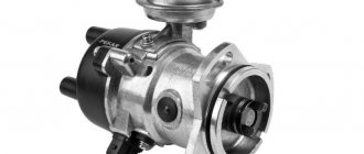
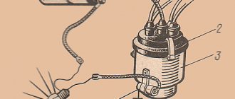
Ignition coil B-117A
The ignition coil is a step-up transformer that converts low voltage pulse current (12V) into high voltage current. The coil windings are installed in a housing made of thin galvanized steel. The housing cover is made of insulating material, has two low-voltage terminals and a socket for a high-voltage wire. The coil body is filled with transformer oil, which cools the windings.
The ignition coil is installed in the engine compartment and secured to the left mudguard of the body with two nuts.
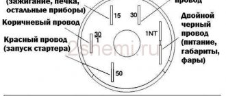
Ignition switch
The ignition switch is a combined switch, consisting of a lock with an anti-theft device and a contact part, assembled in one housing. The switch is installed on the left side of the steering column in a special bracket and secured with two screws.
Spark plug
The spark plug ignites the working mixture in the cylinder with a spark discharge. The design of the candle is non-separable.
For a properly functioning spark plug, the color of the central electrode insulator skirt should be gray or light brown.
| rice. 3 |
The car uses spark plugs A17DVR (A17DVRM) or their analogues.
Maintenance of contact type distributor
In order to repair the distributor yourself, you need to understand its structure and the purpose of all its parts. The operating algorithm of the mechanical distributor is as follows:
- The rotating roller periodically presses the cam onto the spring-loaded movable contact, as a result of which the low voltage circuit is broken.
In fact, 2 electrical circuits pass through the distributor - low and high voltage. The first is periodically broken by the contact group, the second is switched to the combustion chambers of different cylinders.
Now it’s worth considering the functions of the small parts that make up the distributor:
- a coupling mounted on the roller (under the housing) protects internal elements from the ingress of motor lubricant from the power unit;
- the octane corrector wheel, located on the housing boss, is intended for manual adjustment of the spark advance angle;
An important point should be noted: a manual octane corrector is found only on older versions of R-125 distributors. Subsequently, the design changed - instead of a wheel, an automatic vacuum corrector appeared with a membrane operating from engine vacuum.
The chamber of the new octane corrector is connected by a tube to the carburetor, the rod is connected to the movable plate where the breaker contacts are located. The magnitude of the vacuum and the amplitude of the membrane operation depend on the opening angle of the throttle valves, that is, on the current load on the power unit.
A little about the operation of the centrifugal regulator located on the upper horizontal platform. The mechanism consists of a central lever and two weights with springs. When the shaft spins to high speeds, the weights move apart under the influence of centrifugal forces and turn the lever. The interruption of the circuit and the formation of a discharge begins earlier.
Typical faults
Problems with the ignition distributor manifest themselves in one of two ways:
- The engine is unstable - it vibrates, “troits”, and periodically stalls. Sharply pressing the gas pedal causes a pop in the carburetor and a deep dip, the acceleration dynamics and engine power are lost.
- The power unit does not start, although sometimes it “picks up”. Possible shots into the muffler or air filter.
In the second case, the fault is easier to detect. The list of reasons leading to complete failure is relatively small:
- the capacitor or resistor located in the slider has become unusable;
- break in the low voltage wire running inside the housing;
- the cover of the distributor, where the high-voltage wires from the spark plugs are connected, is cracked;
- the plastic slider has failed - a rotor with a movable contact, screwed to the upper support platform and closing the centrifugal regulator;
- The main shaft jammed and broke.
A fracture of the shaft leads to complete failure of the VAZ 2106 engine. Moreover, a fragment with splines remains inside the drive gear, as happened on my “six”. How to get out of the situation while on the road? I removed the distributor, prepared a piece of cold weld mixture and stuck it to a long screwdriver. Then he lowered the end of the tool into the hole, pressed it against the fragment and waited for the chemical composition to harden. All that remains is to carefully remove the screwdriver with a piece of the shaft stuck to the “cold welding”.
There are many more reasons for unstable operation, so they are more difficult to diagnose:
- breakdown of the cover insulation, abrasion of its electrodes or central carbon contact;
- the working surfaces of the breaker contacts are severely burnt or clogged;
- the bearing on which the support plate with the contact group rotates has worn out and become loose;
- the springs of the centrifugal mechanism have stretched;
- the diaphragm of the automatic octane corrector has failed;
- Water has entered the housing.
The resistor and capacitor are checked using a tester; the broken insulation of the cover and slider is detected without any instruments. Burnt contacts are clearly visible to the naked eye, as are stretched weight springs. Diagnostic methods are described in more detail in the following sections of the publication.
Tools and preparation for disassembly
To repair a VAZ 2106 distributor yourself, you need to prepare a simple set of tools:
- 2 flat screwdrivers with a narrow slot - regular and short;
- a set of small open-end wrenches measuring 5-13 mm;
- pliers, round nose pliers;
- technical tweezers;
- probe 0.35 mm;
- hammer and thin metal attachment;
- flat file, fine sandpaper;
- rags.
If you plan to completely disassemble the distributor, it is recommended to stock up on aerosol lubricant such as WD-40. It will help displace excess moisture and make it easier to unscrew small threaded connections.
During the repair process, you may need additional equipment and materials - a multimeter, a bench vice, pliers with pointed jaws, motor oil, and so on. There is no need to create special conditions to carry out the work; the distributor can be repaired in a regular garage or in an open area.
To avoid problems with setting the ignition during assembly, it is recommended that before removing the element, fix the position of the slider according to the instructions:
- Unclip the clamps and remove the cover, move it to the side along with the wires.
To dismantle the distributor, you need to disconnect the vacuum tube from the membrane block, disconnect the coil wire and unscrew the only fastening nut with a 13 mm wrench.
Problems with the lid and slider
The part is made of durable dielectric plastic; in the upper part there are terminals - 1 central and 4 side. High-voltage wires are connected to the sockets from the outside; from the inside, the terminals are in contact with a rotating slider. The central electrode is a spring-loaded carbon rod in contact with the brass rotor pad.
A high-potential pulse from the coil is applied to the central electrode, passes through the slider contact pad and resistor, then goes to the desired cylinder through the side terminal and armor wire.
To identify problems with the cover, it is not necessary to remove the distributor:
- Using a screwdriver, unscrew the 2 steel clamps and remove the part.
- Disconnect all cables by pulling them out of their sockets.
- Carefully examine the cover body for cracks. If any are found, the part will definitely change.
- Examine the condition of the internal terminals, wipe off graphite dust from the walls. Pads that are too worn may have poor contact with the runner and burn. Cleaning will help temporarily, it is better to change the spare part.
- The spring-loaded “coal” in the center should move freely in the socket; cracks and chips are unacceptable.
Don't be afraid to mix up high-voltage cables when disconnecting. On the top of the cover there are cylinder numbers, which are easy to navigate.
An insulation breakdown between two contacts is diagnosed as follows:
- Unscrew any spark plug (or take a spare one), remove the cover and disconnect all armor wires except the central one.
- Attach the spark plug to the ground of the car and use the second wire to connect it to the first side electrode on the cover.
- Turn the starter. If a spark appears at the spark plug electrodes, there is a breakdown between the side and main terminals. Repeat the operation on all 4 contacts.
Not knowing such subtleties, I went to the nearest auto store and bought a new cover with the condition of return. Carefully swapped parts and started the engine. If the idle speed leveled out, I left the spare part on the car, otherwise I returned it to the seller.
The slider malfunctions are similar - abrasion of contact pads, cracks and breakdown of the insulating material. In addition, a resistor is installed between the rotor contacts, which often fails. If the element burns out, the high-voltage circuit is broken and a spark is not supplied to the spark plugs. If black marks are detected on the surface of a part, its diagnostics is necessary.
Important note: when the slider becomes unusable, there is no spark on all spark plugs. An insulation breakdown is diagnosed using a high-voltage cable coming from the coil. Pull the end of the wire out of the cover, bring it to the central contact pad of the slider and turn the crankshaft with the starter. A discharge appears, which means the insulation is broken.
It's easy to check the resistor - measure the resistance between the terminals with a multimeter. A value of 5 to 6 kOhm is considered normal; if the value is more or less, replace the resistance.
Video: how to check the functionality of the slider
Troubleshooting Contact Group Problems
Since a spark jumps between the contact surfaces when opening, the working planes gradually wear out. As a rule, a protrusion is formed on the movable terminal, and a depression is formed on the static terminal. As a result, the surfaces do not fit well, the spark discharge weakens, and the motor begins to “trouble.”
A part with minor wear is restored by cleaning:
- Remove the distributor cap without disconnecting the cables.
- Using a screwdriver, push the contacts apart and insert a flat file between them. The task is to remove the build-up of the moving terminal and level the static terminal as much as possible.
- After cleaning with a file and fine sandpaper, wipe the group with a rag or blow with a compressor.
In stores you can find spare parts with modernized contacts - holes are made in the center of the working surfaces. There are no depressions or growths on them.
If the terminals are worn to the limit, it is better to change the group. Sometimes the surfaces are deformed to such an extent that it is impossible to adjust the gap - the feeler gauge is inserted between the bump and the recess, leaving too much clearance at the edges.
The operation is performed directly on the car, without dismantling the distributor itself:
- Disconnect and remove the cover with wires. There is no need to turn the starter or adjust the timing marks.
- Use a short screwdriver to loosen the screw securing the wire and disconnect the terminal.
- Unscrew the 2 screws holding the part to the metal plate and remove the breaker.
Installing the contacts is not difficult - screw the new group with screws and connect the wire. Next - adjust the gap to 0.3-0.4 mm, performed using a feeler gauge. You need to turn the starter a little so that the cam presses on the plate, then adjust the gap and fix the element with the adjusting screw.
If the working surfaces burn too quickly, it is worth checking the capacitor. Perhaps it has dried out and is not performing its function well. The second option is a low quality product, where the opening surfaces are offset or made of ordinary metal.
Bearing replacement
In distributors, a roller bearing is used for the correct operation of the octane corrector. The element is combined with a horizontal platform where the contact group is attached. A rod coming from the vacuum membrane is attached to the protrusion of this platform. When the vacuum from the carburetor begins to move the diaphragm, the rod rotates the platform along with the contacts, adjusting the moment of sparking.
During operation, play occurs on the bearing, which increases with wear. The pad, together with the contact group, begins to dangle, opening occurs spontaneously, and with a small gap. As a result, the VAZ 2106 engine operates very unstable in any mode, power is lost, and gasoline consumption increases. The bearing is not repaired, only replaced.
The play of the bearing assembly is determined visually. It is enough to open the distributor cover and move the contact breaker up and down with your hand.
Replacement is performed in this order:
- Remove the distributor from the car by disconnecting the coil wire and unscrewing the fastening nut with a 13 mm wrench. Don't forget to prepare for dismantling - turn the slider and make chalk marks as described above.
- Dismantle the contact group by unscrewing 3 screws - two are fastening, the third holds the terminal.
- Using a hammer and a thin tool, knock out the locking rod from the oil deflector clutch. Remove the last one from the shaft without losing the second washer.
Installation of the new element is carried out in the reverse order. Before installing the inside of the distributor, it is advisable to thoroughly clean it. If rust has formed on the roller, remove it with sandpaper and lubricate the clean surface with engine oil. When you insert the shaft into the housing sleeve, do not forget to adjust the contacts according to the feeler gauge.
When installing the distributor, maintain the original position of the body and runner. Start the engine, loosen the nut securing the element and turn the housing to achieve the most stable operation. Tighten the fastening and check the “six” while driving.
Video: how to correctly change a bearing without marking
Other faults
When the engine categorically refuses to start, you should check the functionality of the capacitor. The technique is simple: put an assistant behind the wheel, remove the distributor cap and give the command to rotate the starter. If a barely noticeable spark jumps between the contacts or is not observed at all, feel free to buy and install a new capacitor - the old one can no longer provide the required discharge energy.
Any experienced driver who operates a “six” with a mechanical distributor carries a spare capacitor and contacts. These spare parts cost pennies, but the car won’t run without them. I was convinced of this from personal experience when I had to look for a capacitor in an open field - a passing Zhiguli driver helped me and gave me his own spare part.
Owners of a VAZ 2106 with a contact distributor are also plagued by other minor troubles:
- The springs holding the weights of the centrifugal corrector are stretched. Small dips and jerks appear when the car accelerates.
- Similar symptoms are observed in case of critical wear of the vacuum diaphragm.
- Sometimes the car stalls for no apparent reason, as if the main ignition wire had been pulled out, but then it starts and runs normally. The problem lies in the internal wiring, which has broken and periodically breaks the power circuit.
It is not necessary to change stretched springs. Unscrew the 2 screws securing the slider and, using pliers, bend the brackets where the springs are attached. A torn membrane cannot be repaired - you need to remove the assembly and install a new one. Diagnostics is simple: disconnect the vacuum tube from the carburetor and draw air through it with your mouth. A working diaphragm will begin to rotate the plate with contacts through traction.
Video: complete disassembly of the ignition distributor VAZ 2101—2107
Diagnostics of malfunctions of the ignition module of injection VAZ 2107
The ignition of the injection VAZ 2107 is completely electronic and is considered quite reliable. However, problems can arise with it too. The module plays an important role in this.
Signs of a malfunctioning ignition module
Symptoms of a faulty module include:
- the Check engine warning light on the dashboard lights up;
- floating idle speed;
- engine tripping;
- dips and jerks during acceleration;
- change in sound and color of exhaust;
- increased fuel consumption.
However, these signs can also appear in case of other malfunctions - for example, in case of problems with the fuel system, as well as in case of failure of some sensors (oxygen, mass air flow, detonation, crankshaft position, etc.). If the engine starts to operate incorrectly, the electronic controller puts it into emergency mode, using all available resources. Therefore, when the engine operation changes, fuel consumption increases.
In such cases, you should first of all pay attention to the controller, read information from it and decipher the error code that has occurred. To do this, you will need a special electronic tester, available at almost any service station.
If the ignition module fails, error codes in engine operation may be as follows:
- P 3000 - no sparking in the cylinders (for each cylinder the code may look like P 3001, P 3002, P 3003, P 3004);
- P 0351 - break in the winding or windings of the coil responsible for cylinders 1–4;
- P 0352 - a break in the winding or windings of the coil responsible for 2–3 cylinders.
At the same time, the controller can produce similar errors in the event of a malfunction (break, breakdown) of high-voltage wires and spark plugs. Therefore, before diagnosing the module, you should check the high voltage wires and spark plugs.
Main malfunctions of the ignition module
The main malfunctions of the VAZ 2107 ignition module include:
- a break or short to ground in the wiring coming from the controller;
- lack of contact in the connector;
- short circuit of the device windings to ground;
- break in the module windings.
Checking the ignition module
To diagnose the VAZ 2107 injection module, you will need a multimeter. The verification algorithm is as follows:
- Raise the hood, remove the air filter, find the module.
- We disconnect the block of the wiring harness coming from the controller from the module.
- We set the multimeter to measure voltage in the range 0–20 V.
- Without starting the engine, turn on the ignition.
- We connect the negative (usually black) probe of the multimeter to ground, and the positive one to the middle contact on the harness block. The device must display the voltage of the on-board network (at least 12 V). If there is no voltage or it is less than 12 V, the wiring or the controller itself is faulty.
- If the multimeter shows a voltage of at least 12 V, turn off the ignition.
- Without connecting the connector with wires, disconnect the high-voltage conductors from the ignition module.
- Switch the multimeter to resistance measurement mode with a measurement limit of 20 kOhm.
- To check the device for an open circuit in its primary windings, we measure the resistance between contacts 1a and 1b (the outermost ones in the connector). If the resistance of the device tends to infinity, there is indeed an open circuit in the circuit.
- We check the module for breaks in the secondary windings. To do this, we measure the resistance between the high-voltage terminals of the first and fourth cylinders, then between the terminals of the second and third cylinders. In operating condition, the module resistance should be about 5–6 KOhm. If it tends to infinity, the circuit is broken and the module is faulty.
Contactless distributor
In "sevens" with a contactless ignition system, a distributor of type 38.3706 is used. As already mentioned, the design of a non-contact distributor is similar to a contact one, with the exception of the mechanism responsible for creating electrical impulses in the low-voltage circuit of the system. Here, instead of a contact group, this function is performed by a Hall sensor. As for the malfunctions of the non-contact distributor, they are the same as those of the contact distributor, therefore, it is not advisable to consider them again. But it’s worth talking about the sensor in detail.
A Hall sensor is installed in the contactless distributor instead of a contact group
Hall Sensor
The operation of the sensor is based on the phenomenon of induction. The design of the device is based on a permanent magnet and a hollow cylindrical screen with four cutouts in the form of a crown. The screen is fixedly fixed on the distributor shaft. As the shaft rotates, the protrusions and cutouts of the “crown” pass through the groove of the magnet. This alternation causes a change in the magnetic field. Signals from the sensor are sent to a switch, which converts them into electrical impulses.
The operation of the sensor is based on the phenomenon of inductance
If the Hall sensor fails, the engine may not start at all, or it starts with difficulty and runs intermittently. The sensor cannot be repaired, but you can check its functionality yourself.
Hall sensor check
There are several ways to diagnose a sensor. The simplest of them involves replacing the device being tested with a known good one. The second method is to measure the voltage at the sensor terminals using a voltmeter. Measurements are taken at terminals 2 and 3 of the device. The voltage between them should be 0.4–11 V. If there is no voltage or it does not correspond to the specified parameters, the sensor must be replaced.
The voltage between pins 2 and 3 should be 0.4–11 V
You can check the device's functionality by simulating its operation. To do this, you need to disconnect the central high-voltage wire from the distributor cover, insert a working spark plug into it and place it so that the “skirt” touches the “ground” of the car. Next, you need to disconnect the sensor connector from the distributor, turn on the ignition and connect terminals 2 and 3 to each other. If a spark appears on the spark plug during a short circuit, the sensor is working, otherwise the device must be replaced.
Hall sensor replacement
To replace the sensor, you will need to remove the distributor from the engine. The order of further work is as follows:
- Remove the cover by unfastening the latches.
- We dismantle the slider.
- Using a drift and pliers, remove the shaft coupling mounting pin.
- We remove the shaft from the housing.
- Disconnect the vacuum corrector rod.
- Using a flathead screwdriver, unscrew the two screws that secure the sensor.
The sensor is secured with two screws - Remove the Hall sensor.
Once the screws are unscrewed, the sensor can be easily removed - We install a new part in its place.
- We assemble and install the distributor in the reverse order.
About the ignition system in detail
The ignition system of a gasoline internal combustion engine “breathes” due to spark formation on the SZ elements, which ignite the mixture in the combustion chamber. Obviously, the efficiency of the fuel combustion process, the functioning of the engine as a whole, etc. directly depend on the timing of ignition. For this reason, the ignition must be set to the most optimal position for normal operation.
Most modern cars are equipped with electronic ignitions that do not require any adjustments. However, for the normal functioning of cars with a carburetor ignition system equipped with a 4-stroke internal combustion engine, adjustment is required. It is thanks to this that timely sparking is guaranteed.
Correct adjustment of the distributor
The first sign that something wrong is going on with the ignition system is characteristic knocks and noises while the car is driving.
A 4-stroke internal combustion engine operates according to the following scheme:
- First, fuel is injected.
- Then the compression stroke occurs.
- A working stroke is in progress, during which a spark is generated that ignites the mixture.
- Finally, the last step is the release of the working.
Ignition, to be more precise, occurs not during the working moment, but at the border of the compression stroke and the working stroke. At this very moment, the SZ produces a spark that ignites the fuel mixture.
Important point. The SZ is required to produce a spark at the moment when the motor piston almost reaches a position called TDC.
Setting the ignition on the distributor
It happens that the moment of operation of the SZ becomes a little off as time passes, which entails a decrease in the time of effective spark action. The time interval between reaching TDC and ignition of the fuel is called ignition timing. Its value is determined by a numbered scale marked on the crankshaft flywheel.
Purpose of the distributor cover
The design of the ignition distributor cap (aka distributor) has remained and remains virtually unchanged throughout the entire history of the use of this device as part of the ignition system of gasoline engines:
Let's look at the design and operating principle of this much-needed part.
The distributor cap is a molded part made of non-electrically conductive material (insulator) that has the following device:
- Metal contacts are pressed into this part - these are the side and central electrodes
- The number of side electrodes strictly corresponds to the number of engine spark plugs (but not cylinders, do not forget that there are engines in which there is more than one spark plug for each individual cylinder); the distributor cover on the VAZ 2109 in our case has four side electrodes
- A high-voltage (armor) wire coming from the ignition coil is connected to the central electrode from the outside
- To the side electrodes - high-voltage (armor) wires going to the spark plugs
- Inside the cover itself there is a central contact equipped with a terminal that has a spring-loaded contact element (“carbon”), which transmits voltage to the central (main) contact of the distributor rotor (ignition distributor)
Schematic design of the lid
- When installing the cover on the distributor body, it is important to take into account not only the order in which the armored wires are connected, but also the orientation of the cover in relation to the “nose” of the runner is also important
- The ignition distributor cap is attached to the distributor body using latches or screws (the distributor cap on the VAZ 2109 is secured with screws)
- To prevent the formation of condensation under the lid, it has a special ventilation hole
Switch
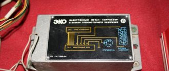
The commutator is necessary to create an electrical impulse by interrupting the constant supply of current from the battery to the primary winding of the coil. The BSZ VAZ 2107 uses a switching device of type 3620.3734. The working elements in it are ordinary bipolar transistors, which open the circuit when a signal is received from the Hall sensor.
Switch 3620.3734 is built according to a simple single-wire circuit, in which the device body is connected to the vehicle ground and, accordingly, to the negative terminal of the battery. The advantages of using this unit instead of a traditional breaker include:
- no need for maintenance or adjustment;
- high spark energy, which makes it easier to start the engine in the cold season, as well as the ability to use gasoline with a lower octane number;
- the presence of a stabilization system that protects the Hall sensor from voltage surges.
Purpose and types of distributors
The main distributor of the “six” is located on a horizontal platform made to the left of the engine valve cover. The unit shaft, ending with splines, enters the drive gear inside the cylinder block. The latter rotates by the timing chain and at the same time rotates the oil pump shaft.
The distributor performs 3 functions in the ignition system:
- at the right moment it breaks the electrical circuit of the primary winding of the coil, causing a high voltage pulse to form in the secondary;
- alternately directs discharges to the spark plugs according to the operating order of the cylinders (1-3-4-2);
- automatically adjusts the ignition timing when the crankshaft speed changes.
The spark is supplied and the air-fuel mixture is ignited before the piston reaches the upper extreme point, so that the fuel has time to fully burn. At idle, the advance angle is 3-5 degrees; with increasing crankshaft speed, this figure should increase.
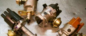
Various modifications of the “sixes” were equipped with different types of distributors:
- VAZ 2106 and 21061 were equipped with engines with a working volume of 1.6 and 1.5 liters, respectively. Due to the height of the block, distributors with a long shaft and a mechanical contact system were installed on the model.
- VAZ 21063 cars were equipped with a 1.3 liter engine with a low cylinder block. The distributor is a contact type with a shortened shaft, the difference for models 2106 and 21063 is 7 mm.
- The updated VAZ 21065 series was equipped with contactless distributors with a long rod, working in conjunction with an electronic ignition system.
The difference in the length of the drive shaft, depending on the height of the cylinder block, does not allow the use of the VAZ 2106 part on a 1.3 liter engine - the distributor simply will not fit into the socket. Installing a spare part with a short shaft on a “clean six” will also not work - the splined part will not reach the gear. The rest of the filling of the contact distributors is the same.
As a young, inexperienced driver, I personally encountered the problem of different lengths of ignition distributor rods. On my Zhiguli VAZ 21063, the distributor shaft broke off on the road. At the nearest auto store I bought a spare part for the “six” and began installing it on the car. Result: the distributor was not inserted completely; a large gap remained between the platform and the flange. Later the seller explained my mistake and kindly replaced the part with one suitable for the 1.3 liter engine.
Ignition marks VAZ 2107
When adjusting the advance angle, you must focus on the marks marked on the crankshaft pulley and on the front engine cover.
There is a notch on the engine pulley that should align with one of three marks on the cover, depending on the fuel used.
The marks on the lid are of different lengths - short, medium and long. The first corresponds to an advance angle of 10 degrees, the second - 5 degrees, the third - 0 degrees (the mixture is ignited at TDC).
High octane fuel burns faster than low octane fuel. The VAZ 2107 is designed for gasoline with an octane number of 92-95, so the optimal advance for it is 5 degrees.
How to remove the distributor drive
I decided to set the ignition wisely and ran into the following problem: the distributor was installed at the factory in such a way that it does not spin in the direction I want it to, and apparently I will have to remove the drive and rearrange it. It is not clear from the books how to do this correctly; there is something going into the oil pump, some kind of plate... In general, I have never dealt with such an engine design. Therefore, tell me, are there any pitfalls in this operation?
What other ones? If the distributor drive plate does not get into the slot of the oil pump, then there will be no movement of oil through the lubrication system. So, write your letters in small handwriting. The engine will burn out. I’m not sure about this, but it’s better if this particular operation (installation of the drive) is performed by a motor mechanic at a service station or another experienced person. And you can set the ignition yourself on an already installed drive. Although, as I was told, “the drive won’t get in any other way than it should,” but here it’s better to be on the safe side. A very responsible operation.:roll:
I decided to set the ignition wisely and ran into the following problem: the distributor was installed at the factory in such a way that it does not spin in the direction I want it to, and apparently I will have to remove the drive and rearrange it. It is not clear from the books how to do this correctly; there is something going into the oil pump, some kind of plate... In general, I have never dealt with such an engine design. Therefore, tell me, are there any pitfalls in this operation?
There is no need to remove the drive. Just move the wires in the cover in the desired direction, one wire forward or backward, and turn the distributor.
Tell me urgently if anyone knows! This is the situation on the loaf. Before I removed the drive with the distributor, they were looking for the reason why it wouldn’t start. When I barely started it, problems appeared: the engine was not picking up speed, there was absolutely no oil pressure, the knocking in the engine depended on the crankshaft speed. Is this a bummer for the engine?
Remove the T, B, and the drive, it looks like the drive shank did not hit the oil pump. Check the drive for integrity of the pins. And then put everything right. Remove the sump, the seat on the pump may have rolled up, and install the drive with the sump removed (it’s clear whether it’s hit or not).
The drive was removed at the very end of the plate that is inserted into the pump; there is a bump, as if it had been licked off a little.
Kotska is the point of contact of the feather in the slot of the pump shaft. Everything is fine :) When installing the drive, don’t forget to set it according to the manual, otherwise you’ll then turn the distributor trying to start the engine: D
Prerequisites for failure
Please note that the engine control system malfunction warning lamp, located on the device panel in the signaling unit, is the first indicator of deviations in the operation of the VAZ 2107, where an injector is used. Some modifications of the VAZ 2107 provide for the location of the warning lamp on the upper insert of the radio panel. By starting the ignition, a system malfunction is tested, which means the lamp lights up and goes out after the engine starts.
A prerequisite for diagnosing the ignition system is that the lamp does not go out when the engine is running.
By starting the ignition, a system malfunction is tested, which means the lamp lights up and goes out after the engine starts. A prerequisite for diagnosing the ignition system is that the lamp does not go out while the engine is running.
In situations where there is a malfunction, VAZ 2107 owners replace the spark plugs. Old factory spark plugs are usually replaced with iridium spark plugs from NGK or Denzo. Do not forget that only those spark plugs that are designed for the appropriate type of injection are suitable here.
The type of ignition system is no less important in determining the parameters of the spark plug. Often such manipulation does not provide much improvement (plugs have a fairly long service life), so the non-contact ignition system undergoes a full diagnosis.
Do you want to know more about how to install
valve timing according to marks on VAZ 2101- VAZ 2107
? And so.
Ignition distributor-distributor "seven"
The distributor is used to generate pulse voltage in the low-voltage circuit of the ignition system, as well as distribute high-voltage pulses among the spark plugs. In addition, its functions include automatic adjustment of the spark advance angle.
What kind of distributors are there?
In the VAZ 2107, depending on the type of ignition system, two types of distributors can be used: contact and non-contact. In appearance they are practically no different. The difference between them lies in the device responsible for generating a pulse in the low-voltage circuit of the system. For the former, a group of contacts is responsible for this function, for the latter - an electromagnetic sensor, the operation of which is based on the Hall effect. In all other respects, the operating principle of the devices is identical.
General tips for connecting high-voltage wires.
Checking high-voltage wires. To check the wires, you will need a multimeter tester. Check the resistance of the wires - it should be no more than 20 KOhms (in practice, the longest wire of cylinder 1 has a resistance of up to 10 KOhms). If the wire resistance is more than 20 Kom, it must be replaced. Carefully inspect the wires for chafing on parts of the motor or other wires. In case of significant abrasion, replace the wire. In case of minor abrasion, it is possible to lay the wire so that it does not rub and fix it in this position.
Laying wires. Do not try to connect the wires in a bundle. Disassemble the wiring harnesses, release the wires from the plastic holders. Connect the high-voltage leads to the corresponding cylinder spark plugs. Lay the wires so that they do not rub against each other, engine parts, or hoses. Avoid sharp bends and tension on the wires. After connecting all the wires, secure them into the bundle with special comb holders included in the delivery kit.
The procedure for connecting I/O wires to a VAZ carburetor (2108, 2109, 21099)
The central wire from the distributor cover always goes to the ignition coil (bobbin).
The outlet of the distributor cover, which faces towards the front of the car, is connected to the first cylinder.
The outlet of the distributor cap, looking down, is connected to the third cylinder.
The outlet of the distributor cap, looking rearward, is connected to the fourth cylinder.
The outlet of the distributor cap, looking up, is connected to the second cylinder.
The procedure for connecting high-voltage wires to a VAZ Classic, Niva with a carburetor and distributor.
Central wire from the ignition coil (bobbin)
1 cylinder - above the vacuum corrector. Next, clockwise, the order is 1-3-4-2.
Distributor device with Hall sensor
On the VAZ-2109, the manufacturer installed a contactless type distributor equipped with a Hall sensor. It is four-spark, additionally equipped with a centrifugal and vacuum corrector.
In addition to correctors, the device has other elements that contribute to proper operation. Thus, the distributor is equipped with a special plastic screen. It is necessary to protect the working surfaces of the mechanism from dust and dirt. The slider mounted on the distributor rotor has a constant resistance of about 1 kOhm. In addition, the design includes thrust washers, lock washers and O-rings. The body is one-piece, aluminum.
Installation of contactless ignition on VAZ-2107 cars
The first step, of course, is to purchase a set of equipment for contactless ignition. We advise you to purchase an ignition kit only from trusted places. Do not forget to read the instructions for the purchased device
It is important that the contactless ignition kit matches the technical characteristics of your car
Pay attention to the length of the distributor shaft - it should not differ from the size of the shaft installed on your machine
The standard contactless ignition kit includes the following parts:
- coil;
- distributor;
- connecting wires;
- switching unit;
- four DVRM spark plugs;
- high-voltage wires (set).
To successfully install a contactless ignition system, you must follow a certain sequence of actions. The first step is to turn off the power to the car; to do this, remove the negative terminal from the battery. Next, we disconnect all the wires, including the main high-voltage wire, from our ignition coil. Now you can remove the distributor cover. We set the distributor slider to a certain position so as not to disturb the existing ignition settings. It is also necessary to place a mark on the engine block in order to correctly install the new distributor
Be sure to pay attention that the mark should be placed in the middle of the five slots that are located at the bottom of the distributor. After these manipulations, you can unscrew the nut and remove the old contact ignition distributor
Before directly installing the new distributor, you must remove its cover and place the slider in the same position as on the old distributor. Only after this can the distributor be inserted into the hole in the engine block. Next, align the marks and clamp the distributor body with a nut.
We reassemble: install the cover, screw it on and connect the wires. Now let's move on to the ignition coil. We disconnect and carefully remove the old coil, then install a new one in its place. We connect the second end of our central high-voltage wire to the coil, and put aside the brown wire that previously went from the distributor to the coil; we will no longer need it.
We put all high-voltage wires in their places. We connect two brown wires to the new coil - to contact “K”, and connect two blue wires to the contact marked “B”.
We decide on the place where the switch will be attached. You can install it near the washer reservoir. It is attached to the body using self-tapping screws. We connect the connector to the switch and tightly twist the wires with electrical tape.
We start the engine and adjust the operation of the contactless ignition system.
Video: “BSZ - contactless ignition system”
Installing an electronic BSZ instead of a contact one
Today it is very rare to find a “seven” with contact ignition. With the arrival on sale of switches, distributors and coils for electronic spark generation systems, owners of classics began to massively re-equip their cars.
DETAILS: Replacing the air filter on a Hyundai Solaris with your own hands
What is included in the BSZ kit
In addition, you will need spark plugs (preferably new ones) with a gap of 0.7–0.8 mm and a set of high voltage wires. Coil type B-117A (used in a contactless system) is not suitable for electronic ignition. Its characteristics do not correspond to those of other equipment in the circuit.
Preparation
Before installing a new VAZ-2107 distributor for a contact ignition system, you need to adjust the gap between the contacts of the breaker. It is more convenient to do this with the device removed from the car. We check the gap with a flat feeler gauge. The value is set from 0.35 to 0.45 mm.
In this case, the protrusion of the cam should move the moving contact away from the stationary contact as much as possible. We adjust by slightly loosening the screws, and then tighten them more firmly and check the gap again. Contacts that have worked hard may have a protrusion on one and a depression on the other, which interferes with adjustment.
Before removing the old distributor, mark its position relative to the cylinder block with a marker. You also need to accurately mark the position of the moving contact (slider) relative to the body. If all this is not done, the settings will be violated and the engine will not start.
Installation
Having established exactly the same position of the roller in the body on the new distributor, carefully insert it into the hole in the block, slightly turning the roller to align the splines. Having “planted” the device in place by rotating the body relative to the block, we set the approximate advance angle, as on the old distributor.
Secure with a washer and nut, but not too tight. Now you need to plug in the high voltage wires. This is easy to do - each contact on the distributor cover has the number of the cylinder to which it needs to be connected. We connect the wire from the ignition coil to the central terminal.
The wires should fit tightly, with a slight tension, the protective caps should be pushed all the way down. Don’t get carried away, don’t bend the petals of the wire tips too much, otherwise later, when you try to remove them, you’ll tear off the wires “with their roots”! A wire goes from the contact wire to the “K” terminal of the ignition coil, usually it is green.
If your VAZ-2107 is equipped with a contactless ignition system, then you need to connect a connector with three wires. Having plugged it into the socket, check the fit of the wires; it happens that they “crawl out” of their places and the device does not work. Everything is done, the new distributor is installed and ready for use.
What does the distributor consist of?
A device such as a distributor includes a large number of different parts. It is not the purpose of this material to consider their purpose, but you can see what components the distributor consists of in the figure below
As can be seen from the figure, the distributor consists of several independent units. And if the purpose and operating principle of the voltage distributor unit are simple and clear, then you can familiarize yourself with the work of others in more detail. However, it is advisable to check the condition of the high-voltage distributor and slider each time the car is serviced.
Centrifugal regulator
Such a device determines the moment when fuel assemblies begin to burn in the engine cylinders. As already noted, a spark initially appears when the piston reaches the TDC position, and it is at this moment that the distributor is initially adjusted. However, two points need to be taken into account:
- Combustion of fuel assemblies occurs at a constant speed, starting from the spark plug and then spreading further throughout the volume of the cylinder. Combustion does not occur instantly, and the greatest efficiency of a gasoline internal combustion engine is achieved when the piston has passed TDC and reached BDC (bottom dead center).
- When the engine is running, the crankshaft speed changes; increasing it reduces the time required for efficient combustion of the fuel assembly.
To eliminate this contradiction, the concept of CVD is introduced, which implies the start of fuel combustion before the piston reaches TDC. The device that ensures the formation of the UOZ is a centrifugal regulator, shown in the figure; it consists of weights connected by springs and a plate.
Its operating principle is based on centrifugal force; an increase in crankshaft speed causes the weights to diverge, and through the plate - a change in the position of the cam and the runner. This will cause the contacts to open sooner and will also cause high voltage and spark to occur earlier. The fuel assembly will ignite when the piston position has not reached TDC, which will ensure its efficient combustion.
Distributors from different manufacturers have a similar adjustment of the fuel assembly ignition moment, including in VAZ 2109, 2106, 2107, 2108.
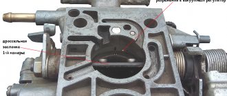
Vacuum regulator
Such a device is designed to change the SOP when the engine load changes, determined by the position of the throttle valve. The following figure will help you understand how this is done:
The vacuum regulator is a closed cavity separated by a diaphragm. One of the cavities is connected to the carburetor. The vacuum created in it, depending on the position of the throttle valve, causes the diaphragm to move. A change in its position is transmitted through the rod to the movable disk, which affects the position of the breaker cams, adjusts the time of its operation (earlier or later), and, accordingly, the ignition time of the fuel assembly.
Thus, the distributor, depending on the load on the engine, changes the moment of spark formation, affecting the characteristics of the engine. This adjustment is present in all VAZ 2109, 2106, 2107, 2108 cars, and the joint operation of the described regulators can ensure efficient engine operation over the entire range of loads and crankshaft speeds.
Octane corrector
This device allows you to mechanically change the OZ depending on the fuel used (octane number) or its quality. You can see the corrector in the figure below.
In fact, these are two plates, one is installed on the distributor and has an arrow, the other is attached to the engine, and there are marks on it. By changing their position in relation to each other, you can mechanically set the desired ignition angle. This is required mainly when using different types of gasoline.
How to remove the distributor drive
I tried to remove the subject on the ZMZ-2401 engine.
Nothing worked. Then I started calling my teammates and trying to apply all the advice. There is no result. Before this I removed the drives twice, but on 402x. Even my dead drive came out relatively without problems. We turned the crooked starter for a very long time while simultaneously trying to remove the drive - it didn’t help.
I understand the simple methods, I tried everything. I don’t have a very good idea of what the next steps might be: remove the rocker arm axle, rods, take out the pushers, unscrew the timing gear cover and try with the three of you to turn the crankshaft, move the camshaft along the axis and pull out the distributor drive?
What else can be tried if the case turns out to be particularly advanced?
_________________ Laziness is the Great Engine of Technical Progress, and the Toad is its brake
Sha , Apparently you didn’t read the instructions well. especially the point where it says “Light blows of a heavy hammer.”
So if that doesn’t work out, then there may be several options.
1) The weight of the sledgehammer is not the same (select experimentally, carry out each subsequent iteration with a hammer at least half a kilogram heavier) 2) The blow is not light enough (try different blow forces with different hammers. From very easy, to “YES IT IS in %: ?)
PS. Yes, it is mandatory to thoroughly wipe everything with monitor wipes after each operation.
_________________ The further society moves away from the truth, the more it hates those who talk about it. A monstrous amount of false speculation is circulating around the world, and the worst thing is that half of them are pure truth.
_________________ The further society moves away from the truth, the more it hates those who talk about it. A monstrous amount of false speculation is circulating around the world, and the worst thing is that half of them are pure truth.
Merlin , stupid comment.
It’s one thing to put what you have in order, and quite another to buy yourself a new hemorrhoid.
Merlin , stupid comment.
It’s one thing to put what you have in order, and quite another to buy yourself a new hemorrhoid.
dimok24 , I was looking for a replacement engine to easily capitalize mine. Naturally, I’m greedy - I’m absolutely not ready to buy expensive 402 or 24d, because... The car is unlikely to cover 5 thousand kilometers on it. — I don’t travel much. They offered the engine cheaply. It’s working, but it’s been removed from the car, and the carrier has been sawn into scrap metal - it’s impossible to start it and measure the compression, for starters. I began to remember where my engine gave me trouble and went there. The first was the distributor drive. I really wanted to look at the teeth of its gear. In this case, the unscrewed drive moved on the studs by 1-2mm, and then rested. The engine turned easily and naturally with a crooked starter. The oil was not drained from the engine - the level is normal, in appearance - better than mine after 3 thousand km. But the adjusting screws in the rocker arms also turned out to be tightly tightened. Even with me they protrude more (adjusted for the smaller thermal gap for 24d) - I concluded that the camshaft has lived a long life.
In general, I was not ready for the investment of time and effort that this engine would require. I'll try to do without a replacement engine.
Sha , if it moves 2 mm then I don’t know what’s wrong with it. You need to remove the pan, oil pump and see what holds it there. Although there is one guess, perhaps the drive has already been rebuilt and the hex pin has been re-coiled, the cotter pin has been flared poorly or a long cotter pin has been taken, it came out and is now caught on the camshaft gear or the block casting. The devil knows, anything can happen.
The cleanliness of the oil for the 24th and 402nd engines is not an indicator; it can be replaced, but the engine is trashed. The first sign is that the engine is all covered in oil and the crankcase gas cleaning hose goes to the ground. The second sign is that the engine turns easily with the spark plugs screwed into the pump or crankshaft pulley.
Tightly tightened screws are not an indicator of camshaft wear, it indicates that the head is for 76 gasoline, and the rods are for AI-93.
Was. I turned it with a handle - it turns much easier than mine.
Time zone: UTC + 2 hours [Summer Time]
Who's at the conference now?
This forum is currently viewed by: no registered users and guests: 0
Source
In what cases is ignition installation necessary?
There are several symptoms by which a car owner can determine that it is necessary to adjust and set the ignition breaker:
- Inability to start the engine.
- Increased gasoline consumption. Of course, this may be due to the need to adjust the carburetor, but this also happens. For example, if the ignition is set later, the dynamics of the car will be low, and in order to accelerate normally, the engine needs more air-fuel mixture.
- The appearance of shots in the silencer. If the explosion follows, it will take some time for the gases to expand. In the event that the piston reaches BDC, the exhaust stroke will be next, which means that a certain part of the fuel will be transferred to the exhaust system. Accordingly, pops will appear as a result.
- The power unit began to operate noisier. and you will need to install 2106 correctly in case of shaking and tripping of the engine. The upward piston makes the operation of the power unit more rigid, and the explosion of the mixture will occur towards it.
Setting the ignition to "six"
Octane corrector
It's no secret that the gasoline we buy at gas stations often does not meet the standards provided by the car manufacturer for normal engine operation. As a result of using such fuel, clogging of the fuel system, an increase in the amount of deposits on piston parts, and a decrease in engine performance may occur. But the most dangerous thing for the power unit is detonation, which occurs due to the use of low-octane gasoline.
In cars with an electronic control system, detonation is eliminated using a special sensor and control unit. Such elements are found in injection “sevens”. The computer receives the signal from the sensor, processes it and automatically adjusts the ignition timing, increasing or decreasing it. The carburetor VAZ 2107 does not have such equipment. Drivers have to do this manually, turning the distributor in the manner described above.
But there is a special electronic device that makes it possible not to adjust the ignition angle after each refueling. It's called an octane corrector. The device consists of two parts: an electronic unit, which is installed in the engine compartment, and a control panel located in the car interior.
Noticing that the piston fingers begin to “ring”, the driver turns the knob on the control panel of the device, making the ignition later or earlier. Such a device costs approximately 200–400 rubles.
The “seven” distributor is indeed a complex device, but if you understand the design and operating principle, you can easily maintain, repair and adjust it yourself.
Device malfunctions
Replacement and repair of the distributor on the domestic “six” is carried out in the event of incorrect operation of the mechanism.
Below are the main symptoms of breakdowns that indicate possible malfunctions:
- The vehicle jerks while driving. Moreover, these jerks are completely uncharacteristic of a car.
- The engine generally does not start.
- When trying to accelerate the car, the car may also jerk, and the acceleration process itself takes a lot of time, and the engine may detonate - the piston rings knock.
- Increased fuel consumption.
As you can see, in general the symptoms are similar to those that appear when the ignition is set incorrectly. Of course, if such symptoms appear, it cannot be said for sure that the fault lies in the distributor, but attention should also be paid to diagnosing this unit.
As for the breakdowns that may force the car owner to repair or replace the mechanism, they are as follows:
- The unit slider is worn out and burnt out.
- The problem lies in the cover itself - the contacts on it could have burned out.
- Hall sensor failure. The problem may be associated not only with a breakdown of the controller, but also with poor contact on the regulator plug.
- Another reason that domestic drivers encounter quite often is the distributor bearing. After a long period of use, it could become loose, but it could also simply jam.
- Presence of mechanical damage, including cracks on the cover.
- Engine fluid gets into the distribution unit; usually the problem is related to the seal of the cap.
Loading …
Replacing the distributor and its parts on a VAZ 2109
Distributor location: Located next to the battery, at the end of the cylinder head cover. See the photo below for more details:
When to change the distributor? It fails quite rarely; most often the distributor parts, such as the slider, distributor cover and others, must be replaced. Below is a list of malfunctions that occur in the engine when the distributor or its components fail:
- the car starts to jerk;
- the car simply won’t start;
- loss of power from the car engine, the car drives worse;
- increase in vehicle fuel consumption.