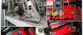
Causes and possible consequences of the malfunction
The generator may not work for the following reasons:
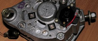
- malfunction of the voltage regulator (“pills”, “chocolates” in the slang of car enthusiasts);
- wear (destruction) of brushes;
- short circuit of the exciting winding (rotor);
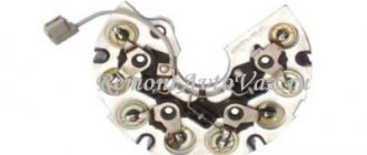
- breakdown of diodes (located in the horseshoe);
- wear of bearings and bushings.
A faulty voltage regulator usually results in a lack of battery charge. In this case, the “battery” indicator light appears on the dashboard. The engine continues to run until the battery is discharged to approximately 8 - 9 volts.
During daylight hours, the battery charge may be enough for 30-50 kilometers, provided that the battery was well charged at the time the malfunction occurred.
If the output stages of the voltage regulator breakdown, a malfunction may occur due to an increase in the generator output voltage to 17 - 20 Volts. This recharges the battery. The consequence of overcharging is the process of boiling of the electrolyte. If signs of corrosion appear under the hood in the battery area, it is necessary to check the generator.
A breakdown of the diode bridge can occur when the battery is accidentally reversed (installing the terminals in the wrong polarity). Typically, diodes are punched in pairs in one arm. A faulty diode has a resistance close to zero. In this case, the stator winding of the generator operates in short circuit mode and becomes very hot.
After a few minutes of engine operation, the windings overheat, and a smell of burnt electrical wiring appears under the hood of the car. To avoid fire, the engine must be turned off and the generator checked.
Wear of the brushes leads to gradual failure of the generator. First, while driving, the charge indicator light on the dashboard begins to blink, then it begins to glow constantly. In many generator models, the brushes are changed together with the voltage regulator.
A short circuit in the generator windings can lead to a significant change in output parameters and overheating of the device.
Basic problems
If the generator begins to act up, then the main causes of the malfunction should be sought either in the on-board network, or these are problems with the generator itself. If the generator gives a charge, but not enough, then perhaps it has been “loaded” too much by installing many other gadgets in addition to the standard electrical equipment, and it is already working at the limit of its capabilities.
Our motorists really love tuning the VAZ 2110, adding, for example, speaker power, enhancing the light, etc. In such cases, some people change the battery, for example, installing it with a capacity of 70 Ah, instead of the usual VAZ one with 55 Ah.
But although this may help at first, over time such a battery will run out even faster, since a standard generator will not be able to provide it with a full charge; it does not have enough power for this.
Initial check sequence
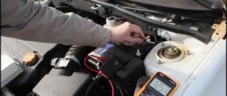
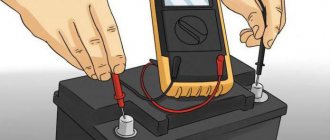
An initial performance check can be performed without dismantling the generator. To do this, set the multimeter switch to the “constant voltage 20V” mode. Next, connect the black probe to the negative terminal of the battery, the red one to the positive terminal. After this, you need to start the engine and let it reach a stable idle speed. Multimeter readings ranging from 13.5 to 14.5 Volts are considered normal.
If the multimeter shows a value less than 12.8 Volts, the charging process either does not occur at all, or the charging current is extremely small. The generator is operating in abnormal mode. When the voltage is more than 14.8 Volts, the battery is overcharged. This can lead to boiling of the electrolyte, an increase in acid concentration, and destruction of the battery plates.
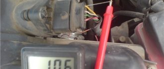
To check the voltage at the generator output, you need to turn on the car lamp in the open circuit from terminal 30 on the generator (the point of contact with the thick wire leading to the positive terminal of the battery or starter).
Next, connect the multimeter in the “=20V” mode with the red probe to contact 30 of the generator, and the black probe to the stripped contact on the engine or body. Start the engine. The reading on the multimeter should not be more than 15.5 volts whenever the accelerator pedal is pressed. Otherwise, further operation of the generator is dangerous for the electrical equipment of the car.
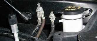
When checking, you should evaluate the degree of tension of the generator belt. Using a simplified method, this can be done by pressing on the belt with your finger.
The amount of deflection should be within 0.5 - 1 centimeter. At the same time, check the degree of belt wear. To determine the reasons for abnormal operation of the generator and perform repair work, dismantling the generator is required.
Lamp test
A lamp test is testing a generator using a “fog light”. The diagnostic task is to determine whether the generator rotates correctly when exposed to drill speeds. In this case, the light bulb plays the role of an indicator - if the generator rotates normally, then it (the light bulb) should light up.
Alternator test lamp
It is important to know that a working generator should produce a voltage within 14.1-14.5 V. And at the same time, the voltage should not jump or have differences. In other words, the voltage must be stable.
To carry out this type of testing, the autogenerator will have to be removed from the car and the following steps must be taken:
- clamp it in a vice so that it is convenient to work;
- integrate a battery with the generator.
It is highly recommended to be careful when connecting the battery to the generator and not to mix up the contacts. An incorrect connection will lead to a short circuit, which can easily burn out the dynamo.
We also advise you to find out the type of generator before diagnosing. As you know, they are different in terms of connection. This means that the units may have a different number of contacts. There are 2-pin, 3-pin or 4-pin generators.
4-block generators contain the following contacts:
- a plus of a constant type, marked by the Latin S;
- plus associated with ZZ - IG;
- contact for control unit marked M;
- for the warning lamp – L.
We continue with a series of actions:
- a positive cable is run from the battery to both “+” dynamos;
- a lamp with a value of 50 W is integrated to the desired contact;
- voltage is applied to the lamp;
- the generator is rotated using a drill;
- The indicator light is tested.
So, if the light is bright and the voltage on the dynamo is within normal limits, then the generator is fully operational. In any case, it is capable of recharging the battery.
The connection between the generator and the battery is an important tandem. Under no circumstances should you disconnect the battery while the engine is running! Ask why? This unnecessarily loads the voltage stabilizer and generator, which causes a failure in the overall system. This can even be seen from the indicator: if the lamp under test is disconnected from the battery, then if the dynamo is working, it will continue to glow, but the voltage will no longer be stable.
Is the generator shorting or not?
The battery should also not be disconnected due to a simple short circuit. A short circuit will burn not only the unit itself, but also the electronic units installed in the car.
So, the rule not to remove the terminals from the battery under any circumstances must be included in the list of the main canons of the motorist. Those who like to “light” the battery do the wrong thing, which often happens in the winter season. Keep a charger in your car and don't push your luck. Once or twice you'll be lucky, but on the third you can burn down the entire electrical system.
Checking generator components
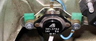
The test begins with monitoring the functionality of the voltage regulator. To do this, the regulator is removed from the generator and a simple electrical circuit is created.
Any car interior light bulb can be used as an incandescent lamp. If voltage regulator 3 is working properly, lamp 6 should not glow at full power. When connected in parallel with the lamp (brushes) of a multimeter, its readings should be from 5.0 to 10.0 Volts. If the multimeter readings fall outside these limits, the regulator must be changed. The design of some generator models allows for the possibility of replacing the regulator without dismantling the device.
Next, check the exciting winding of the generator for breakdown. To do this, set the multimeter to resistance measurement mode at a limit of 200 kiloOhms. The probes are connected: black - to the commutator lamella, red - to the metal part of the armature. The resistance should be more than 100 kiloohms or higher than the upper limit of measurement, as shown in the photo.
The resistance between the lamellas (rotor windings) is usually 0.5 - 2 Ohms.
Checking the stator begins with checking the windings for breakdown. To do this, the red probe of the multimeter is connected to the metal part of the stator, the black probe is connected in series to the windings.
The resistance must be above the upper measurement limit. Then the resistance between the winding contacts is measured. They should differ by no more than 5%. The measurement limit of the multimeter is set to 200 ohms.
If the winding has an electrical breakdown, a short circuit of the turns or a break, it must be replaced. There are workshops that rewind stators and rotors.
To check the health of the diode bridge, the multimeter measurement mode is switched to the “diode” test. Then the diodes (their number on a horseshoe is usually 9) are sequentially “ringed” in forward and reverse connection. In the forward direction (black probe to the cathode) the resistance is 550 - 700 Ohms, when switched in reverse it is greater than the maximum measurement limit.
When the diodes breakdown, the resistance in all directions will be practically zero. This diode should be changed. The difficulty of replacing a diode lies in the fact that the diodes in generators are not soldered, but spot welded to ensure reliable contact at different temperature conditions.
A car generator is an important part of a car's electrical equipment. At the first sign of inoperability, it is necessary to check it using a multimeter.
Voltage regulator - its main functions
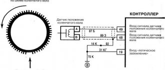
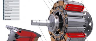
On a VAZ 2110 car, the voltage potential in the generator is formed under the influence of alternating current. This phenomenon becomes possible due to the presence of silicon diodes in the generating device of the vehicle. The generator rotor (the rotating component of the mechanism) operates according to the following diagram:
- First, the crankshaft begins to function, which is affected by the current;
- the crankshaft sets the movement of the rotor;
- After this, the generating device itself begins to work.
All stages of the sounded process are monitored by a voltage regulator, which is also often called a relay. It is this that is considered the main control unit of the generator.
Without a regulator, the current-generating mechanism of the VAZ 2110 will not perform its tasks, which are listed below:
- starting the generator;
- control (in offline mode) of current supply;
- “holding” in a certain voltage range.
The described relay cannot be repaired. In the event of a breakdown, the regulator must be replaced, which is done after checking the functionality of this unit.
Generator stator
The stator windings can only be examined by disconnecting or unsoldering the leads from the diode bridge. The resistance between the terminals of the windings should be approximately 0.2 Ohm. And between the terminal of any winding and 0 (common terminal) there is about 0.3 Ohm. If the stator windings or diode bridge are shorted, the generator makes a loud noise during operation.
Also carefully inspect the condition of the internal parts of the stator and the outer part of the rotor. They should not touch each other during operation. As they say, “shoes.” During such operation, the generator makes increased noise, which indicates wear of the bearings or bushings.
Video, testing on a homemade stand:
Winding break
If the excitation winding is broken, then there is no charging of the battery. To determine this, it is often enough to place your hand on the generator. When it breaks, it heats up. For an accurate check, you need to disconnect the end of the excitation winding from the brush, connect the battery wires to it, and connect the battery wires to terminal Ш of the generator (via a voltmeter or a light bulb).
If there is a break, the voltmeter needle will not deflect and the light bulb will not light up. To find which of the coils prevents the generator from working, connect the wires from the battery to each individually. Finally, check the soldering and coil terminals. If the break is internal, the coil needs to be replaced; for external ones, soldering helps.
Diode bridge
A diode bridge consists of two plates, one of which is positive and the other negative. Diodes are checked with a multimeter in ohmmeter mode.
Connect one probe to the “+” terminal of the diode bridge, and alternately connect the second to terminals F1 F2 F3 and 0. To make it clearer: we connect one probe to the positive plate, and with the other we alternately touch the terminals of those diodes that are pressed into this plate.
Then swap the probes and do the same. In one case the tester should show conductivity (some kind of resistance), but in the other it should not. So we checked the diodes on the positive plate.
To check the diodes on the negative plate, connect one probe to the negative plate, and the second to the leads of the diodes alternately. In exactly the same way, then we swap the probes and repeat the procedure. In one case there will be conductivity, in the other there will not be.
Brushes and slip rings
Rings and brushes can be checked visually, assessing their condition and serviceability. Check the protruding length of the brushes. It must be at least 4.5 mm. And the norm is 8-10 mm.
Also, the diameter of the slip rings must be at least 12.8 mm. and ideally 14.2-14.4. Worn rings can be replaced if you find them in a store. They are removed with a special puller, and the winding terminals are unsoldered. After installing new rings, they can be turned on a lathe to eliminate runout and sanded with fine sandpaper to eliminate burrs.