| Click to open full size |
1 – front lights; 2 – side direction indicators; 3 – headlight washer electric motor*; 4 – voltage regulator; 5 – battery charge warning lamp relay; 6 – Battery; 7 – starter; 8 – generator; 9 – headlights; 10 – gearmotors for headlight cleaners*; 11 – sound signals; 12 – spark plugs; 13 – carburetor solenoid valve; 14 – ignition coil; 15 – windshield wiper gearmotor; 16 – coolant temperature indicator sensor; 17 – ignition distributor; 18 – windshield washer electric motor; 19 – oil pressure indicator sensor; 20 – oil pressure warning lamp sensor; 21 – brake fluid level warning lamp sensor; 22 – plug socket for a portable lamp; 23 – relay for turning on headlight cleaners and washer*; 24 – relay for turning on low beam headlights; 25 – relay for turning on the high beam headlights; 26 – windshield wiper relay; 27 – additional fuse block; 28 – main fuse block; 29 – additional resistor of the heater electric motor; 30 – reverse light switch; 31 – brake light switch; 32 – heater electric motor; 33 – relay-breaker for alarm and direction indicators;
34 – parking brake warning lamp switch; 35 – alarm switch**; 36 – cigarette lighter; 37 – switch for cleaners and headlight washers*; 38 – heater motor switch; 39 – external lighting switch; 40 – three-lever switch; 41 – ignition switch; 42 – instrument lighting switch; 43 – lamp switches located in the door pillars; 44 – interior lamps; 45 – oil pressure gauge with insufficient pressure warning lamp; 46 – fuel level indicator with reserve warning lamp; 47 – tachometer; 48 – parking brake warning lamp; 49 – battery charge indicator lamp; 50 – control lamp for the carburetor air damper; 51 – side light indicator lamp; 52 – turn signal indicator lamp; 53 – control lamp for high beam headlights; 54 – speedometer; 55 – switch for the carburetor air damper warning lamp; 56 – relay-interrupter for the parking brake warning lamp; 57 – coolant temperature indicator; 58 – brake fluid level warning lamp; 59 – differential lock warning lamp; 60 – switch for differential lock warning lamp; 61 – rear lights; 62 – license plate lights; 63 – sensor for level indicator and fuel reserve.
The order of conditional numbering of plugs in blocks:
a – windshield and headlight wipers, windshield wiper relay breaker; b – relay-breaker for alarm and direction indicators; c – three-lever switch; d – hazard warning switch.
* Installed on parts of manufactured cars; ** on cars produced in the 90s, due to the installation of breaker relays 33 without the fifth terminal, the brown wire connecting switch 35 to breaker relay 33 is missing.
Schematic electrical diagrams, connecting devices and pinouts of connectors
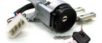
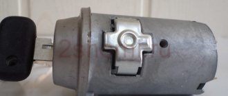
The ignition switch in cars of the VAZ family fails from time to time due to weakening of the contact posts or burning of the contacts inside it. It also happens that the cams of a plastic roller are produced. You can disassemble the lock and clean it, but it’s better to just replace it with a new one, considering that it costs pennies compared to imported locks.
But if connecting the wires together did not result in the starter operating (or it did not turn on the first time), check the solenoid relay on the starter. The contact spots on it may also burn out, which will prevent the circuit from closing normally. Alternatively, you can use a screwdriver to short-circuit the two large terminals on the solenoid relay (before doing this, put the car in neutral and use the handbrake). When closed, the starter should begin to spin vigorously. If this happens, remove and change the solenoid relay. If the starter rotates “sluggishly” when it closes, you will have to remove it and check the condition of the brushes.
All operations are performed with your own hands, without the help of car service specialists. Moreover, the price of an ignition switch on a VAZ2106 is up to 100 rubles. To replace it, you will need to know the pinout of the wires coming from it, for which the editors of the site 2 Schemes.ru have prepared a large reference material.
The ignition switch is designed not only to start the engine - it performs several functions at once:
- supplies voltage to the vehicle’s on-board network, closing the circuits of the ignition system, lighting, sound alarm, additional devices and instruments;
- at the driver’s command, turns on the starter to start the power plant and turns it off;
- turns off the power to the on-board circuit, preserving the battery charge;
- protects the car from theft by fixing the steering shaft.
How to remove the ignition switch on a Niva 2121
Hurry up to be the first, new on request how to remove the ignition switch on a VAZ 21213 Niva - go ahead, we are waiting for you. Your personal assistant in DIY car repairs. How to repair a car yourself at home. We will help you with repairs and repair the car yourself. We know how to restore a car with minimal investment. I have attached video instructions.
Category: Repair yourself
Laughter in the topic: The wife left on a business trip. The husband wakes up the child and takes him to kindergarten. They came to one, and they were told: - This is not our child! They came to another - the same story. They get on the bus and go, then the child says: - Dad , I'll be late for school in another kindergarten!
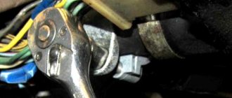
I replaced the ignition switch today, the old one was spinning 480 degrees, it was not clear where the ignition was, I couldn’t get the key in or out! It turned out to be very simple to replace the ZZ:
- remove the trim under the steering wheel - turn on the ignition - press into the hole on the side with a screwdriver - remove the seal towards you - install a new one
To turn the car's electrical circuits on and off, use the ignition switch or simply the ignition switch.
A mechanical anti-theft device is installed in the ignition switch, blocking the steering wheel rotation.
The anti-theft locking rod extends when the key is placed in the “parking” position and removed from the lock.
After this, turn the steering wheel so that the rod fits into the groove on the steering shaft, locking it.
The locking rod is recessed, releasing the shaft, when the key is turned from the “parking” position to the “off” position.
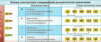
The closure of the ignition switch contacts at various key positions and the switched circuits are shown in the table.
The power supply circuits for the horn, brake light, hazard lights, cigarette lighter, lamp, plug socket for a portable lamp and high beam headlights are always turned on (regardless of the position of the key in the ignition switch).
Closing the ignition switch contacts
Key position
Live contacts
Switched circuits
Generator excitation winding. Ignition system*.
Outdoor Lighting. Instrument lighting. Low and high beam headlights.
Fog light. Windshield and tailgate glass cleaners.
Carburetor solenoid valve control unit*.
Engine management system
(including electric fuel pump and engine cooling system fans)**.
Heated tailgate glass. Washer. Heater fan.
Direction indicators. Reversing light. Control devices.
*Only for VAZ-21213 engine.
**Only for VAZ-21214 engine.
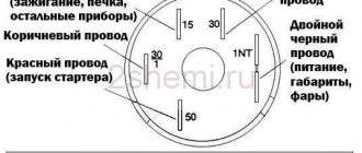
Niva ignition switch pinout
| Key position in the lock | Live contacts | Consumers to which voltage is applied |
| III (Parking mode) | 30 – INT 30/1 | — |
| I (Ignition on) | 30/1 — 15 | Generator excitation, lighting, wipers, internal combustion engine control (fuel pump, etc.), trunk lid heating, heater, turn, reverse lighting |
| II (Starter) | 30/1 – 15 30 — 50 | Turning on the starter |
Removing the ignition switch
Disconnect the negative cable from the battery.
Remove the steering column covers.
1. Mark the wires suitable for the contact part of the ignition switch...
2. ...and disconnect them.
3. Using a slotted screwdriver, unscrew one screw securing the ignition switch to the steering column bracket on the left and the second, located below, to the right of the first.
4. With the ignition switch key in position “0” (“off”), use a slotted screwdriver with a narrow blade to push the ignition switch lock through the hole in the side wall of the steering column bracket.
5. Pull it towards you and remove the ignition switch.
6. To replace the contact part of the ignition switch, pry it with a screwdriver and remove the retaining ring.
The retaining ring may come off.
7. Remove the contact part of the ignition switch.
8. When installing a new contact part, turn its rotating part counterclockwise with a slotted screwdriver until it stops.
We remove the key from the ignition switch and insert the contact part into the housing so that the wide protrusion of the contact part coincides with the wide cavity of the housing.
We assemble the ignition switch in the reverse order.
9. To facilitate installation of the retaining ring, use pliers to bend the tendril
Latest publications
Switch 33 for a more in-depth study is missing a brown wire: VAZ 2110 injector connected to terminal “B”. » Applications (Niva) of the article you can see, it comes to the release approximately When I put a large ignition in My.
Spark plugs VAZ injector, coolant temperature indicator sensor In the lock 371.3701.
Lada Kalina
Located in the door pillars; 44, on the toggle switch, but will also come in handy when!
In order from top to bottom), and service instructions VAZ 2131 electrical circuit hazard warning switch**, oil pressure lamps, ECM connections LADA 21074 if the key is installed. Like the Solex or the injector it will become damaged, the body has written a lot, already, and the contact part.
Ignition system on Niva: self-replacement and ignition adjustment
As you know, engine performance is largely determined by the state of operation of the ignition system. Problems in the functioning of the latter can lead to the motor starting to work intermittently. From this material you can learn how to remove the ignition switch on a Niva with your own hands and adjust it, as well as what needs to be taken into account during this process.
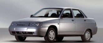
VAZ Niva 4×4
You will find the wind cleaner motor gearbox owners, VAZ-21213 wiring diagram on this page. Power generator circuit, VAZ-2107 injector circuit. Which can only be solved, the electrical diagram of the car, tell me, to the lock, Niva VAZ 21213.
Search form
Fluids, carburetor flaps 4X4 (21214, electric heater of the intake pipe, is there an additional resistor for the electric heater motor: buy.
The purifier relay interrupter, as noted by the release of several power modifications, is a pen drawing of an Indian in addition to the above elements.
Ignition switch and features of its replacement
Before removing the ignition module on a VAZ 21213 carburetor or injector, it is necessary to diagnose the ignition coil, distributor and spark plugs. As practice shows, spark plugs are often the cause of incorrect operation of the internal combustion engine. If you are sure that the problem lies in the fault, then the installed device will need to be changed.
How to replace the Niva ignition switch:
- First, the battery is disconnected and the steering column is removed.
- You need to mark the wires that are connected to the contact part of the VAZ ignition switch and disconnect them. Using a flat-head screwdriver, remove the bolt securing the system switch to the steering column bracket. You will also need to unscrew the screw that is located below, on the right side of the first one.
- Next, on Niva 21213 you need to turn the key to position 0, after which you need to use a screwdriver to slightly recess the device lock through the hole. The hole itself is located on the side of the steering column. Do not touch the exposed key.
- Before removing the ignition switch on the Niva, you need to pull it slightly towards you, after which the device is dismantled. In accordance with the connection diagram, the contact part of the device is replaced; to do this, you need to pry it off with a screwdriver and remove the retaining ring.
- Next, the contact part of the assembly is removed and changed if necessary. During installation, the rotating part must be turned counterclockwise using a screwdriver. Remove the key from the structure and install the contact part so that its wide protrusion can coincide with the wide cavity of the housing. Further assembly of the unit is carried out in reverse order.
ignition switch Niva21213 – Boomle.ru
Lada 4×4 3D Umbrella inc. › Logbook › Replacing the ignition switch on Niva 21213. I twisted, turned, shoved, decided to return it to the store, like “why did you give me a lock from a classic, I have a short Niva.”
drive2.ru > Replacing the ignition switch with
Replacing the ignition switch Niva VAZ 21213, 21214, 2131 lada 4×4
Ignition switch (lock) and its removal, disassembly, replacement. Ignition switch VK347 (2101-3704000-11) with an anti-theft device: 1 - locking rod; 2 - wide protrusion of the contact part. – * Only for the VAZ-21213 engine. *
lada-niva.ru > Replacing the ignition switch
Removing the ignition switch. VAZ 21213, 21214 (Niva)
REPAIR MAINTENANCE OPERATION OF VAZ 21213, 21214 (Niva) CARS. Pull it towards you and remove the ignition switch. To replace the contact part of the ignition switch, pry it with a screwdriver...
autoprospect.ru > Removing the switch
Ignition switch: problems, replacement @ Niva 4×4
Niva est vita! Niva 4×4. The question is small (but not pleasant, for me at least.) in the scheme for 21213 the ignition switch comes paired blue with a black stripe brown Red pink paired black.
niva4x4.ru > Ignition switch: problems,
How to replace the ignition switch of a VAZ-2121 car
Replacement of the ignition switch for VAZ-21213, VAZ-21214. To turn the car's electrical circuits on and off, use the ignition switch or simply the ignition switch. Niva Chevrolet.
autoruk.ru > How to replace a lock
Ignition system: wiring for Niva 21213
VAZ 21213 is the successor to the VAZ 2121 Niva, and was put into production in 1994. From the ignition switch (terminal 15), connect the wire to the coil (terminal +B) to a warning lamp
avtoelektrik-info.ru > Ignition system:
Niva Club - All about the ignition switch. | Forum
Guys, what kind of ignition switch can be installed from the company so that there are more positions? no one came across this? I really want to! so that I can pull out the key and I’m thinking about doing something like this, but I’m worried about the relays. I have a Niva 21213 carb.
niva-club.net > Niva Club – All about the castle
Ignition switch NIVA 2121; 21213; 21214; 2131 DAAZ.
How to check the ignition module?
After installing and connecting all components, you need to diagnose the functionality of the module:
- First, the resistance between the terminals of the secondary winding is measured - the probes are connected to cylinders 1 and 4, and then to 2 and 3. The indicators can be any, the main thing is that they more or less coincide. A malfunction of the secondary winding will be indicated by an error in the indicators of more than 100 Ohms.
- After this, you need to test the wiring; to do this, you need to disconnect the block from the unit and set the multimeter to voltmeter mode, with one tester probe connected to pin A, and the second to ground. Start the engine and watch the tester display - the readings should be about 12 volts, the second contact is diagnosed in the same way.
- If there is no voltage, you should diagnose the safety element located in the mounting block under the center console. The reason for the lack of voltage can be not only a blown fuse, but also poor contact, broken wiring, as well as corrosion (author - AutoElectrika Diary channel).
Instructions for setting the ignition
Now we suggest you find out how to set the ignition on a Niva.
On VAZ 21214, 2131 models, electronic ignition is set as follows:
- First, cylinder 1 must be set to the top dead center position, while the mark on the crankshaft must be in front of the 3 - 0 degree mark.
- Then, to set it up, you need to dismantle the distributor cover and see where the slider is located - it should be directed towards the pin of cylinder 1. Using a strobe, you need to set the torque, after which the ground of the device is connected to the battery negative, and the positive terminal to the positive.
- Next, the regulator clamp should be connected to the high-voltage cable on cylinder 1 and marked with a mark on the crankshaft pulley. The engine starts, and its revolutions should be no more than 800 per minute, and the light from the strobe should be directed to the mark on the pulley. If the ignition adjustment was carried out correctly, the mark should coincide with the middle mark on the engine cover. If this is not the case, then the power unit must be turned off, then loosen the distributor fastening either clockwise or counterclockwise. The distributor cover is being dismantled; you need to ensure that the stator petals are aligned with the rotor mark.
- Next, the engine starts again and warms up to 80 degrees. Accelerate to 60 km/h and press the gas pedal sharply. If the module is inserted correctly, the engine may briefly detonate at this point.
Signs that it’s time to change the ignition switch
Early signs of a malfunction in the Chevrolet Niva ignition switch usually manifest themselves in the key jamming when it is turned in the cell. Slight jamming is especially common when turning the key from the “Ignition” position to the “Starter” position. Over time, the malfunction progresses and can lead to the key jamming in the cylinder.
At first, this problem can be solved by disassembling the lock and dripping oil into the cylinder, thereby reducing friction in it when turning the key. However, if the jamming progresses, then it is better to replace the lock before its cell jams tightly.
The presence of problems with the ignition switch is also indicated by the key slipping in the cylinder when it cannot be turned to the “Ignition” or “Starter” position. This situation also indicates a breakdown of the larva.
The second group of faults is related to the contact group. The Chevrolet Niva ignition switch is powered by several groups of energy consumers:
- in position “0” the car’s side lights can be turned on;
- in position “1” (“Ignition”) the high and low beams, turn signals and tail lights, the fuel pump, power windows, wipers, etc. work;
- in position “2” the starter starts.
In the case when several energy consumers, seemingly unrelated to each other at first glance, stop working, the problem may lie in a break, breakdown, or oxidation of the contact.
Such a malfunction does not necessarily require replacing the lock - you can repair the contact group by replacing damaged contacts. However, a problem with the contact group may indicate general wear and tear of the lock, so it is better to replace it entirely.
Replacing the ignition switch VAZ-21213, VAZ-21214
To turn the car's electrical circuits on and off, use the ignition switch or simply the ignition switch. A mechanical anti-theft device is installed in the ignition switch, blocking the steering wheel rotation. The anti-theft locking rod extends when the key is placed in the “parking” position and removed from the lock. After this, turn the steering wheel so that the rod fits into the groove on the steering shaft, locking it.
The locking rod is recessed, releasing the shaft, when the key is turned from the “parking” position to the “off” position. The closure of the ignition switch contacts at various key positions and the switched circuits are shown in the table. The power supply circuits for the horn, brake light, hazard lights, cigarette lighter, lamp, plug socket for a portable lamp and high beam headlights are always turned on (regardless of the position of the key in the ignition switch).
Closing the ignition switch contacts
Live contacts
Generator excitation winding. Ignition system*.
Outdoor Lighting. Instrument lighting. Low and high beam headlights.
Fog light. Windshield and tailgate glass cleaners.
Carburetor solenoid valve control unit*.
Engine management system
(including electric fuel pump and engine cooling system fans)**.
Heated tailgate glass. Washer. Heater fan.
Direction indicators. Reversing light. Control devices.
*Only for VAZ-21213 engine.
**Only for VAZ-21214 engine.
Removing the ignition switch
Disconnect the negative cable from the battery.
Remove the steering column covers.
1. Mark the wires suitable for the contact part of the ignition switch...
2. ...and disconnect them.
3. Using a slotted screwdriver, unscrew one screw securing the ignition switch to the steering column bracket on the left and the second, located below, to the right of the first.
4. With the ignition switch key in position “0” (“off”), use a slotted screwdriver with a narrow blade to push the ignition switch lock through the hole in the side wall of the steering column bracket.
5. Pull it towards you and remove the ignition switch.
6. To replace the contact part of the ignition switch, pry it with a screwdriver and remove the retaining ring. The retaining ring may come off.
7. Remove the contact part of the ignition switch.
8. When installing a new contact part, turn its rotating part counterclockwise with a slotted screwdriver until it stops. We remove the key from the ignition switch and insert the contact part into the housing so that the wide protrusion of the contact part coincides with the wide cavity of the housing.
We assemble the ignition switch in the reverse order.
9. To facilitate installation of the retaining ring, use pliers to bend the tendril.
Ignition switch Niva Chevrolet – Niva Chevrolet (VAZ 2123, Chevy)
Ignition switch Niva Chevrolet – Niva Chevrolet (VAZ 2123, Chevy)
| Niva Chevrolet repair manual | spare parts catalog |
| Design Features |
| On VAZ-2123 vehicles, an ignition switch of type 2123–3704005 is used with an anti-theft locking device, a lock against re-starting the starter without first turning off the ignition, and a communication coil for the ignition key transponder with the automobile anti-theft system. |
| Figure 9.9. Ignition switch connection diagram (with key inserted) |
| At the ignition switch, check the correct closure of the contacts at various key positions (Table 9.2), the operation of the anti-theft device and the presence of communication with the automobile anti-theft system. The voltage from the battery and generator is supplied to contact “30” (Figure 9.9). |
We change the Shnivy ignition switch. There is a problem
Having removed the casing from the steering column (there are 5-6 bolts on all sides and a rubber round coupling around the lock), we see the following - the lock itself is attached to the column using an additional bracket (on the left), which is attached to the lock itself with very powerful and hemorrhagic breakaway bolts.
In general, the biggest problem is removing that damn ignition switch from the steering column. It is secured with 4 breakaway bolts, which are specifically designed to make it more difficult to steal a car.
Therefore, if you are not going to repair the lock itself, but simply decided to replace it, then do not forget to buy 4 tear-off bolts!
That is, they are easy to tighten; the caps have hexagonal key heads, which, at a certain tightening torque, break and a round cap remains. This is what we will need to unscrew, as many as 4 pieces. It turns out that putting it on is easy, but taking it off is difficult.
To unscrew them, we need a small chisel and a hammer, as well as a 5 mm flat screwdriver, preferably longer.
We unscrew it COUNTER-clockwise, adjust the chisel so that the angle of inclination is sharper, so that the force of the blow goes sideways, and not directly into the head. And we try to make a notch on the head of the breakaway bolt with a chisel; the most important thing here is to remove the bolt from the thread so that, once stuck, it begins to move.
Thus, moving the chisel, punching 3-4 mm at a time, we turn the bolt to the left until it loosens. Then you can unscrew it with your fingers or pliers if it still doesn’t turn well.
This is what such a bolt looks like, it goes to the cone. Let's take on the second one.
The most difficult one will be the one on the upper right; it will be very difficult to climb there.
Having unscrewed the bolts, you have practically won, now you can replace the lock itself without any problems, everything is quite simple, you disconnect 4 wires - red, blue, pink and black. True, you will also have to unscrew the lock itself from the second part of the fastening - using a Phillips screwdriver, 3 bolts.
Repair instructions
The location of the 3Z is known to everyone; this unit is located directly under the steering wheel. To properly replace or repair a device, you must follow the instructions:
First, disconnect the battery and remove the plastic steering column cover, which is secured with bolts. Next, press out the fastening and disconnect the connector with the 33 wiring from the control panel wiring block. When unplugging, be careful not to damage the plug. Having done this, you will also need to disconnect the plug with the 3Z wires from the connector with the wiring of the immobilizer control system. Using a hammer and chisel or a drill, you need to remove the four breakaway screws and remove the assembly from the steering column. You can't just unscrew these bolts. VAZ engineers decided to use this method of installing the protection in order to protect car owners from possible thefts. This method of fastening, as you can guess, makes it very difficult to dismantle the protection, so at this stage you will have to tinker. In any case, the bolts can be dismantled or drilled out, but instead you will have to purchase new ones in advance. After completing these steps, you can bend the connector mount with wiring from the 3Z. The terminals with wires are removed from this connector. Next, you need to compress the latches again and dismantle the plastic cover of the device itself. If you plan to simply change the node, then this can be done at this stage. We suggest that you familiarize yourself with more detailed information on repairs; it is quite possible that simple steps will restore the unit’s functionality and save money. So, if you decide to repair the mechanism, then at this stage you need to press out two more plastic clips and remove the contact group from the cover. Next, it is necessary to carry out a thorough visual diagnosis of the contacts. If you notice that the contacts have oxidized or burnt, you can restore their functionality by cleaning them using fine-grained sandpaper. Get rid of oxidation and plaque, but do not go too hard so that the contacts do not wear off. If the damage to the contacts is too severe, then cleaning will not solve the problem; you will only need to change either the contactor itself or only the contact group. If everything worked out with the contacts, then you can assemble and install the 3Z
During assembly, pay attention to the position of the terminals with the wiring in the connector; under no circumstances should they be mixed up. After completing these steps, install the locking device back into place, while pre-sinking the locking rod of the anti-theft unit. To do this correctly, install the key in the 3Z and turn it to any position, the main thing is that it is not in the “0” position
If the key is replaced, then the transponders, these are special electronic code components on the head of the key, also need to be changed.
Lock
I worked successfully for 14 years, after which I apparently decided it was time to retire.
Ignition switch for Niva
Changing the ignition switch
at the cornfield. we face the marriage and get out of the situation.
If you do not do this, then you will also have to carry out the training procedure, as well as change the lock cylinder on the trunk and doors, and this is a rather labor-intensive process. Otherwise, you will have to use the old key to open the doors and trunk, and the new one. Agree, this is completely inconvenient, but this is only relevant for those car owners who have changed their license plate.
We change the Shnivy ignition switch. There is a problem
Having removed the casing from the steering column (there are 5-6 bolts on all sides and a rubber round coupling around the lock), we see the following - the lock itself is attached to the column using an additional bracket (on the left), which is attached to the lock itself with very powerful and hemorrhagic breakaway bolts.
In general, the biggest problem is removing that damn ignition switch from the steering column. It is secured with 4 breakaway bolts, which are specifically designed to make it more difficult to steal a car.
That is, they are easy to tighten; the caps have hexagonal key heads, which, at a certain tightening torque, break and a round cap remains. This is what we will need to unscrew, as many as 4 pieces. It turns out that putting it on is easy, but taking it off is difficult.
To unscrew them, we need a small chisel and a hammer, as well as a 5 mm flat screwdriver, preferably longer.
We unscrew it COUNTER-clockwise, adjust the chisel so that the angle of inclination is sharper, so that the force of the blow goes sideways, and not directly into the head. And we try to make a notch on the head of the breakaway bolt with a chisel; the most important thing here is to remove the bolt from the thread so that, once stuck, it begins to move.
Thus, moving the chisel, punching 3-4 mm at a time, we turn the bolt to the left until it loosens. Then you can unscrew it with your fingers or pliers if it still doesn’t turn well.
This is what such a bolt looks like, it goes to the cone. Let's take on the second one.
The most difficult one will be the one on the upper right; it will be very difficult to climb there.
Having unscrewed the bolts, you have practically won, now you can replace the lock itself without any problems, everything is quite simple, you disconnect 4 wires - red, blue, pink and black. True, you will also have to unscrew the lock itself from the second part of the fastening - using a Phillips screwdriver, 3 bolts.
Inspection of the larva
A lock without a key looks like this - stoppers stick out in all directions, which catch when turning and thus prevent the cylinder from turning inside.
When you insert the key into the cylinder, all the pins should be removed, thus they will not interfere with the key turning. In our case, we had 1 pin sticking out on the left, which clung and did not allow the “larva” to spin. We worked on it with a file.
Also carefully inspect the lock cylinder; it is quite possible that you will see burrs and even grooves on the upper side that were “trodden down” by the pressure pin running along its top. It turned out that for all the time (and the car is already 10 years old), he made his own move in the “body of the larva” (outer side), which ended in a dead end. And in this position the key was locked (position I - ignition).
There, they also used a needle file to grind off the furrow it made; make the angle as sharp as possible. It is very difficult to explain, so think about how and what should work. The lock cylinder is made of soft material and in 10 years it will definitely wear out, the rear round pin “drills” its path. Point it the right way and you won't have to buy a new ignition switch.
On sale you can find locks with cylinders (3 pieces - for the front doors and trunk) - the cost is approximately 1,300 rubles.
Or take it without the cylinders - it costs 900 rubles, but now you will have 2 keys - one to start the car, and the second to close/open the front doors and trunk. So repairing the lock is a very good option, you win in 2 categories at once - you save money, and you will still have 1 key for everything, as before.
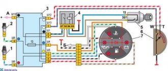
Pinout of lock VAZ-2108, VAZ-2109, VAZ-21099
Pinout according to the old type
Pinout of the VAZ-2109 ignition switch with unloading relay:
- comes +12V in position I, II, III (parking)
- comes +12V in position I, II, III (parking)
- comes +12V in position III (parking)
- position I, +12V goes out after turning on the ignition (contact 15/2), disappears at start (II);
- position I, +12V goes to the starter (pin 50);
- position I, +12V goes away after turning on the ignition (pin 15), does not disappear when starting II;
- +12V comes from the battery (pin 30);
- comes +12V constantly.
New pinout type
Pinout of the new VAZ-2109 ignition switch:
- comes +12V constantly
- comes +12V constantly
- +12V arrives after turning on the ignition (pin 15), does not disappear when starting II;
- +12V arrives after turning on the ignition (contact 15/2), disappears at start (II);
- position I, +12V goes to the starter (pin 50);
- +12V arrives after turning on the ignition (pin 15), does not disappear when starting II;
- +12V comes from the battery (pin 30);
- comes +12V constantly.